1998 HONDA CIVIC engine mount
[x] Cancel search: engine mountPage 269 of 2189
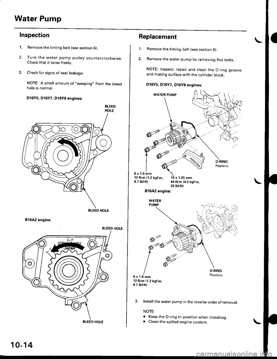
Water Pump
Inspection
't.
2.
Remove the timing belt (see section 6).
Turn the water pump pulley counterclockwise.Check that it tarns freely.
Check for signs of seal leakage.
NOTE: A small amount of "weeping,,from the bleedhole is normal.
Dl6Y5, Dl6Y7, D16Y8 engines:
BLEEDHOLE
B16A2 engine:
BLEED HOLE
BLEED HOLE
BLEED HOLE
10-14
Replacement
6x1.0mm
1.Remove the timing belt (see section 6).
Remove the water pump by removing five bolts.
NOTE: Inspect, repair and clean the O-ring grooveand mating surface with the cylinder block.
D16Y5, D16Y7, D16Y8 engines:
12 N.m {1.2 kgf.m, l0 x 1.25 mm8.7 lbt.ft) {4 N.m 14.5 kg{.m.33 tbt.ft)
Bl642 engine:
WATERPUMP
@;2
6x1.0mm12 N.m 11.2 kg{.m,8.7 tbf.ft)
O.RINGReplace.
3. Install the water pump in the reverse order of removal.
NOTE:
o Keep the O-ring in position when installing.. Clean the spilled engine coolant.
d
orp,
I
Page 355 of 2189
Troubleshooting
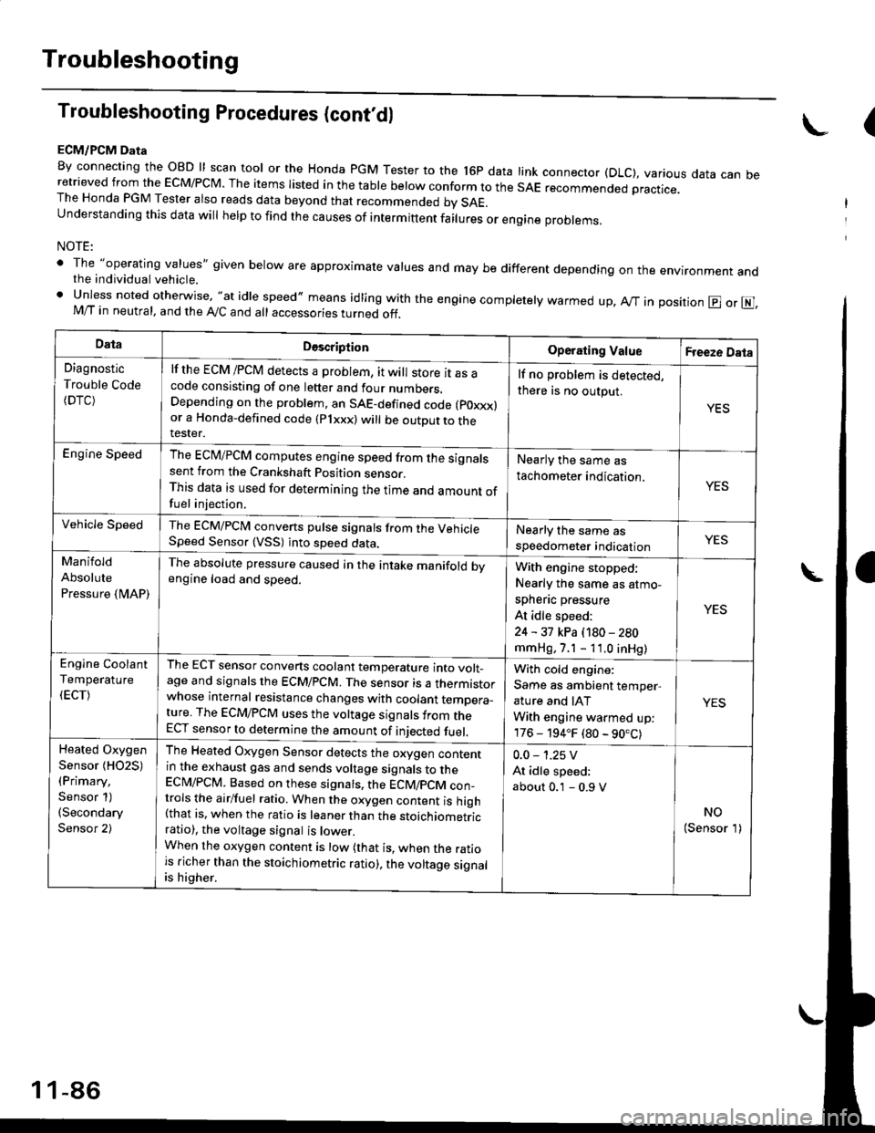
Troubleshooting Procedures (cont,dl
ECM/PCM Data
By connecting the OBD ll scan tool or the Honda pGM Tester to the l6p data link connector (DLC), various data can beretrieved from the EcM/PcM. The items Iisted in the table below conform to the sAE recommended practice.The Honda PGM Tester also reads data beyond that recommended bv SAE.understanding this data wil help to find the causes of intermittent fairures or engine probrems,
NOTE:
' The "operating values" given below are approximate values and may be different depending on the environment andthe individual vehicle.. Unless noted otherwise, "at idle speed,, means idling with the engine completely warmed up, Ay'T in position @ or E],M/T in neutral, and the Ay'C and all accessories turned off.
(
DataDescriptionOperating ValueFreeze Data
Diagnostic
Trouble Code(DTC)
lf the ECM /PCM detects a problem, it will store it as acode consisting of one letter and four numbers.Depending on the problem, an SAE-defined code (poxxx)or a Honda-defined code (Plxxx) will be outDut to therester.
lf no problem is detected,
there is no output.
YES
Engine SpeedThe ECM/PCM computes engine speed from the signalssent from the Crankshaft Position sensor.This data is used for determining the time and amount offuel injection,
Nearly the same as
tachometer indication.YES
Vehicle SpeedThe ECM/PCM converts pulse signals from the VehicleSpeed Sensor (VSS) into speed data.Nearly the same as
speedometer indicationYES
Manifold
Absolute
Pressure {MAP)
The absolute pressure caused in the intake manifold bvengine load and speed.With engine stopped:
Nearly the same as atmo-
spheflc pressure
At idle speed:
24 - 31 kPa (180 - 280
mmHg, 7.1 - 11.0 inHg)
YES
Engine Coolant
Temperature
(ECT)
The ECT sensor converts coolant temperature into volt_age and signals the ECM/PCM. The sensor is a thermistorwhose internal resistance changes with coolant temDera_ture. The ECM/PCM uses the voltage signals from theECT sensor to determine the amount of iniected fuel.
With cold engine:
Same as ambient temper,
ature and IAT
With engine warmed up:
176 - 194.F (80 - 90.C)
YES
Heated Oxygen
Sensor {HO2S)(Primary,
Sensor 1)(Secondary
Sensor 2)
The Heated Oxygen Sensor detects the oxygen contentin the exhaust gas and sends voltage signals to theECI\4/PCM. Based on these signats, the ECM/pCM con_trols the airlfuel ratio. When the oxygen content is high(that is, when the ratio is leaner than the stoichiometricratio), the voltage signal is lower.When the oxygen content is low (that is, when the ratiois richer than the stoichiometric ratio), the voltage signalis higher.
0.0 - 1.25 V
At idle speed:
about 0.1 - 0.9 V
NO(Sensor 1)
1 1-86
Page 356 of 2189
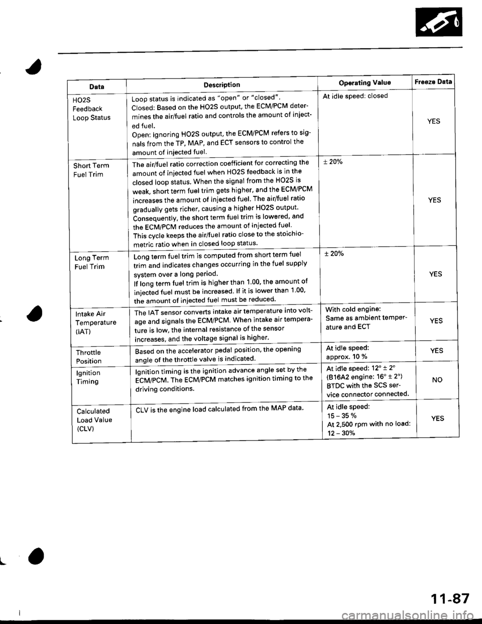
DataDescriotion
Loop status is indicated as "open" or "closed"'
Closed: Based on the HO2S output, the ECM/PCM deter-
mines the airlfuel ratio and controls the amount of inject-
ed fuel.
Open: lgnoring HO2S output, the ECM/PCM refers to sig-
nals from the TP, MAP, and ECT sensors to control the
amount of injected fuel.
The air/fuel ratio correction coefficient for correcting the
amount ot injected fuel when H02S feedback is in the
closed loop status When the signal from the HO2S is
weak, short term fuel trim gets higher, and the ECM/PCM
increases the amount of injected fuel The airlfuel ratio
gradually gets richer, causing a higher HO2S output
Consequently, the short term fuel trim is lowered, and
the ECMiPCM reduces the amount of injected fuel
This cvcle keeps the airlfuel ratio close to the stoichio-
metric ratio when in closed loop status'
Operating ValueF eeza Data
HO2S
Feedback
Loop Status
At idle speed: closed
YES
Short Term
Fuel Trim
! 20%
YES
Long Term
Fuel Trim
Long term fuel trim is computed from shon term fuel
trim and indicates changes occurring in the fuel supply
svstem over a long Period
lf long term fuel trim is higher than 1.00, the amount of
injecGd fuel must be increased. lf it is lower than 1 00'
the amount of injected fuel must be reduced'
! 20%
YES
lntake Air
Temperature
{IAT)
The IAT sensor converts intake air temperature into volt-
age and signals the ECM/PCM. When intake air tempera-
ture is low, the internal resistance of the sensor
increases. and the voltaqe signal is higher'
With cold engine:
Same as ambient temPer'
ature and ECTYES
At idle speed:
approx. 10 %YESThrottle
Position
Based on the accelerator pedal position, the open'ng
angle of the throttle valve is indicated
lgnition
Timing
lgnition timing is the ignition advance angle set by the
gCV/eCV. tn" gCU/PCM matches ignition timing to the
driving conditions.
CLV is the engine load calculated from the MAP data'
At idle speed: 12'i 2'
(81642 engine: 16" t 2")
BTDC with the SCS ser-
vice connector connected.
NO
Calculated
Load Value
{CLV)
At idle speed:
15-35%
At 2.500 rpm with no load:
12 - 30%
YES
ro
11-87
Page 375 of 2189
PGM-FI System
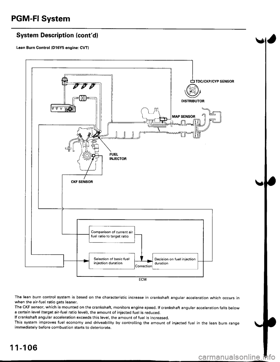
System Description (cont'dl
Lean Burn Control {D16Y5 engine: CvT)
The lean burn control system is based on the characteristic increase in crankshaft angular acceleration which occurs inwhen the air-fuel ratio gets leaner.
The CKF sensor, which is mounted on the crankshaft, monitors sngine speed, lf crankshaft angular acceleration falls belowa certain level (target air-fuel ratio level), the amount of injected fuel is reouceo.
lf crankshaft angular acceleration exceeds this level. the amount of fuel is increased.
This system improves fuel economy and driveability by controlling the amount of injected fuel in the lean burn rangeimmediatelv before combustion starts to deteriorate.
1 1-1 06
TOC/CKP/CYP SENSOR
MAP SENSOR
CKF SENSOR
ECM
Comparison oI current airfuel ratio to target ratio
Page 435 of 2189
PGM-FI System
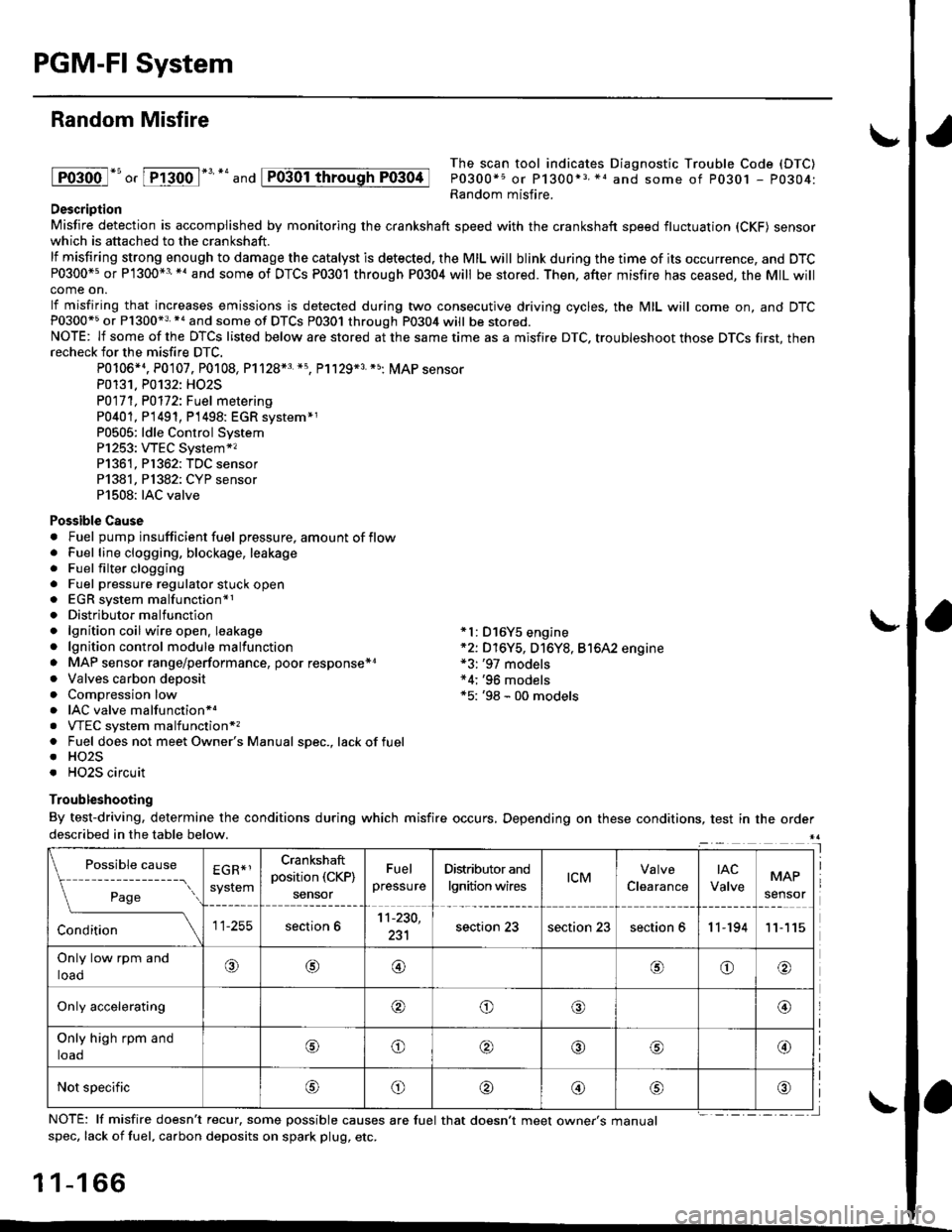
Random Misfire
lFoioo l*u o, [FTioo l*' *' and
The scan tool indicates Diagnostic Trouble Code (DTC)
P0300*5 or P1300*3 *1 and some of P0301 - P0304:Random misfire.Description
Misfire detection is accomplished by monitoring the crankshaft speed with the crankshaft speed fluctuation (CKF) sensorwhich is attached to the crankshaft.
lf misfiring strong enough to damage the catalyst is detected. the MIL will blink during the time of its occurrence, and DTCP0300*5 or P1300*3'*' and some of DTCs P0301 through P0304 will be stored. Then, after misfire has ceased, the MIL willcome on.
lf misfiring that increases emissions is detected during two consecutive driving cycles, the MIL will come on, and DTCP0300*5 or P1300*3 *a and some of DTCS P0301 through P0304 will be stored.NOTE: lf some of the DTCS listed below are stored at the same time as a misfire DTC. troubleshoot those DTCS first, thenrecheck for the misfire DTC.
P0106*4. P0107. P0108, P1128*3 *5, Pl129*3 *5; MAP sensorP0131. P0132: HO2S
P0171, P0112i Fuel metering
P0401, P 1491, P1498: EGR svstem*1P0505: ldle Control SystemP1253: VTEC System*,P1361, P1362: TDC sensorP1381, Pl382: CYP sensorP1508: IAC valve
Possible Cause. Fuel pump insufficient fuel pressure, amount of flow. Fuel line clogging, blockage, leakage. Fuel filter clogging. Fuel pressure regulator stuck open. EGR system malfunction*1. Distributormalfunction. lgnition coil wire open. leakage *l: D16Y5 engine. lgnition control module malfunction *2: D16Y5, D16Y8, Bt6A2 engine. MAP sensor range/performance, poor response*r *3: '97 models. Valves carbon deposit *4;'96 models. Compression low *5: '98 - 00 models. IAC valve malfunctionr.. VTEC system malfunction*,. Fuel does not meet Owner's Manual spec., lackoffuel. HO2S. HO2S circuit
Troubleshooting
By test-driving, determine the conditions during which misfire occurs, Depending on these conditions, test in the orderdescribed in the table below.
Possible
- --^ ---
rage
causeEGR*1
system
Crankshaft
position (CKP)
sensor
Fuel
pressure
Distributor and
lgnition wirestcMClearance
tAc
ValveMAP
sensor
section 611-230,
231section 23section 23section 611-19411
Only low rpm and
loado@@oo
Only accelerating@o@@
Only high rpm and
toaooo@
Not specificoo@
NOTE: lf misfire doesn't recur, some possible causes are fuel that doesn't meet owne/s manualspec, lack of fuel, carbon deposits on spark plug, etc.
1 1-1 66
I
P0304
Page 452 of 2189

\Crankshaft Speed Fluctuation (GKFI Sensor .
firC- 48 Models, '99 - 00 D16Y5 engine with M/Tl
The scan tool indicates Diagnostic Trouble Code (DTC) P1336; Intermiftent interruption in the Crankshaft Speed
Fluctuation (CKF) sensor circuit.
ThescantooIindicatesDiagnosticTroub|ecode{DTC)P1337:NosignaIinthecrankshaftspeedF|uctuation(cKF}
sensor circuit.
D6scription
Thediagnosticsystemhasapu|serrotoronthecrankshaftandapu|sepick-upsensorontheengineblock.TheEcM/PcM
monitors the crankshaft speed ftuctuation based on the cKF sensor signal, and judges that 8n engine misfire occurred if
the fluctuation goes beyond a predetermined limit'
I
fPrk6l
lFr3g7-l
CKF SENSOR 3P CONNECTOR
L:l.)l l.' -Ir-T--T---.]l1 l2l3llL-''---r
CKFM I I CKFP
twrfit 1,.^ | lsLul\.7
Terminal side of male terminals
CKF MIWHT}
CKF PIBLUI
I(cont'd)
- The MtL hds been reported on.- DTC P1336 and/or P1337 a.e
stored.
P.oblem v€rific.tion:1. Do the ECM/PCM Reset Proce-
dure.2. Stan the enginelntormittont lailur6, tY3tom b OK
at thit tima. Chock tor Poor con'
nactions or loota wito! at C102
IC-KF son$rl .nd ECt /PCM, and
mrka suro CKF tonaor mounting
boh ittigM.
Chock for .n open in tho CKF aen-
30t:1. Turn the ignition switch OFF
2. Disconnect the CKF sensor 3P
connector,3. Measure the resista nce
between the CKF sensor 3P
connector terminals No. 1 and
No.3.
ls there 1.6- 3.2 kO?
Ch€ck tor a short in the CKF son'
30tiCheck {or continuitY between
body ground and the CKF sensor
3P connector termin6ls No. 1 and
No.3 individuallY.
(To page 11 184)
1 1-183
Page 454 of 2189
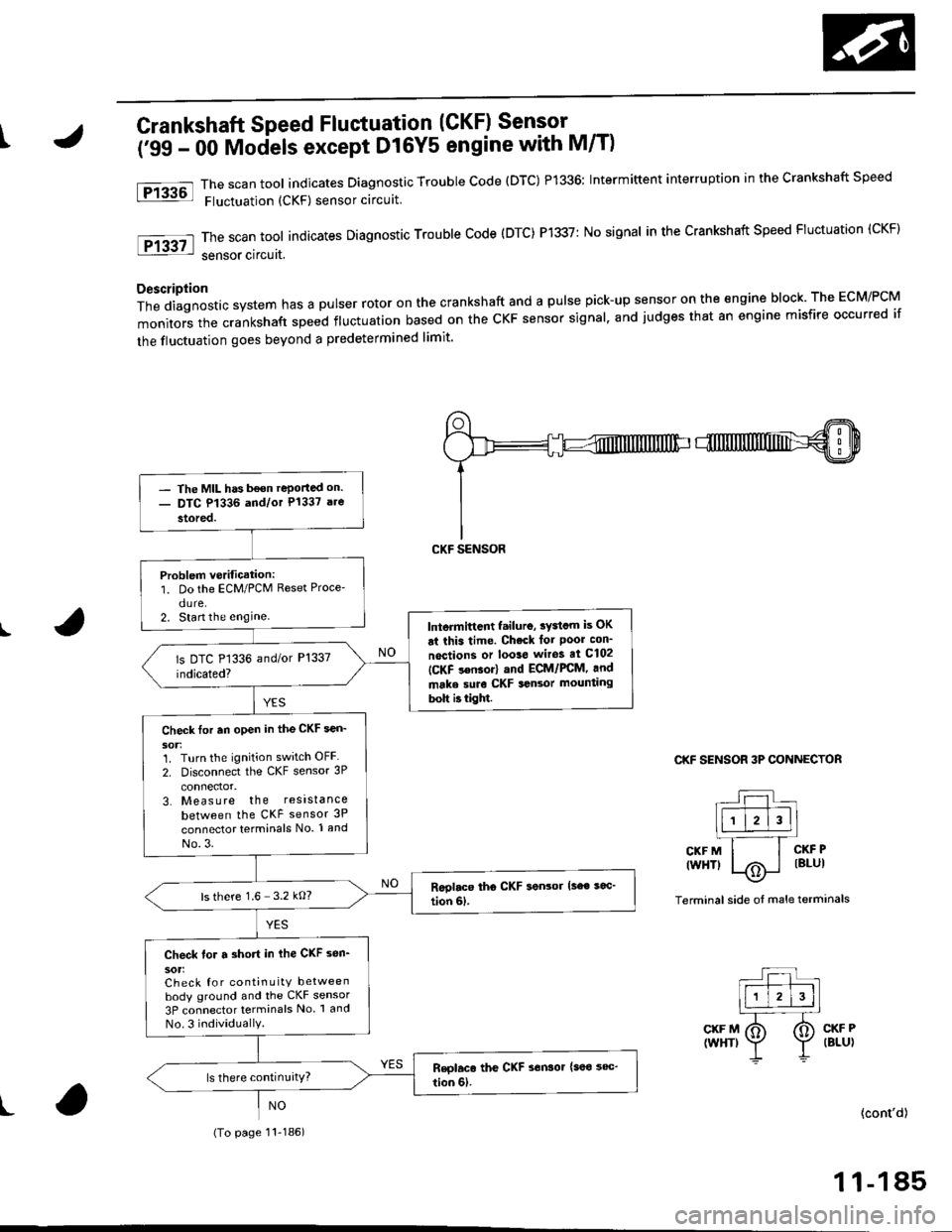
tCrankshaft Speed Fluctuation (CKF) Sensor -
('99 - 00 Mociels except D16Y5 engine with M/T)
The scan tool indicates Diagnostic Trouble code (DTC) P1336: Intermittent interruption in the crankshaft speed
Fluctuation (CKF) sensor circuit
The scan tool indicates Diagnostic Trouble Code (DTC) P1337: No signal in the Crankshaft Speed Fluctuation (CKF)
sensor circuat,
Description
Thediagnosticsystemhasapulserrotoronthecrankshaftandapu|sepick-upsensorontheengineb|ock.TheEcM/PcM
monitors the crankshaft speed fluctuation based on the cKF sensor signal. and judges that an engine misfire occurred if
the fluctuation goes beyond a predetermined limit'
I
Ftu6l
tF13g7l
CKF SENSOR 3P CONNECTOR
r--r t|-.r-r'--]llll l2l3ll.l---'.-T_
CKFM I I CKFP
twHTl |/Ai i lBlul--\9-
Terminal side oI male terminals
CKF M(WHT)CKF P(BLU)
t(cont'd)
1 1-185
- The MIL has b€on reportad on.- DTC P1336 and/or P1337 are
stored.
Problem verification:1. Do the ECM/PCM Reset Proce'
dure.2. Start the enginelntermittcnt failuro, sydcm is OK
ai this time. Check lot Poor con_
noctions or loo3e wiros at C102
ICKF s€nsor) and ECM/FCM, and
make suro CKF sansor mounting
bolt b tight.
Check tor an open in the CKF sen_
1. Turn the ignition switch OFF
2. Disconnect the CKF sensor 3P
3. Measure the resistance
between the CKF sensor 3P
connector terminals No. 1 and
No.3.
ls there 1.6 3.2 kO?
Check for a short in ihe CKF sen_
sot:Check for continuity betweenbody ground and the CKF sensor
3P connector terminals No 1 and
No.3 individuallY.
(To page 11-186)
Page 459 of 2189

ldle Control System
System Description
The idle speed ot the engine is controlled by the ldle Air Control (lAC) Valve.The valve changes the amount of air bypassing into the intake manifold in response to electric current controlled bv theECM/PCM. When the IAC Valve is activated, the valve opens lo maintain the proper idle speed.
D16Y5, D16Y8, Br6A2 engine (M/T):
(ROTARYItac vat-vEEI{GINEcooLAI{T
VARIOUSsEI{SORS
VARIOUSSENSORS
INTAKE MANIFOTDDl6Ys {CVTl, D16Y8 engine lA/T):
D16Y7 engine:
{ROTABY)
;iy--, - ---
11-190