Page 186 of 2189

Gamshafts
Inspection (cont'dl
7. lf the camshaft-to-holder oil clearance is out of tol-
erance:
- And the camshaft has already been replaced, you
must replace the cylinder head.- lf the camshaft has not been replaced, first check
the total runout with the camshaft supported on
V-blocks.
Camshaft Total Runout:
Standard (New): 0.03 mm {0.001 in} max.
Service Limit: 0.04 mm (0.002 inl
- lf the total runout of the camshaft is within toler,
ance, replace the cylinder head.- lf the total runout is out of tolerance. replace the
camshaft and recheck the camshaft to,holder oil
clearance. lf the oil clearance is still out of toler-
ance, replace the cylinder head.
INTAKEEXHAUST
PRIMARY33.088 mm
{1.3027 in)
32.785 mm
(1.2907 inl
MID36.267 mm(1.4278 in)
35.720 mm
{1.4063 in)
SECONDARY34.978 mm(1.3771 inl
3i1.691 mm(1.3658 in)
8. Check the cam lobe height.
Cam lobe height standard (New):
Cam Position
I
INTAKE
MID
EXHAUST
SEC MID PRI
TIB
T/B: TIMING BELTPRI: PRIMARYMID: MID
Check thrs area lor wear.
Page 189 of 2189

Cylinder HeadValve Guides
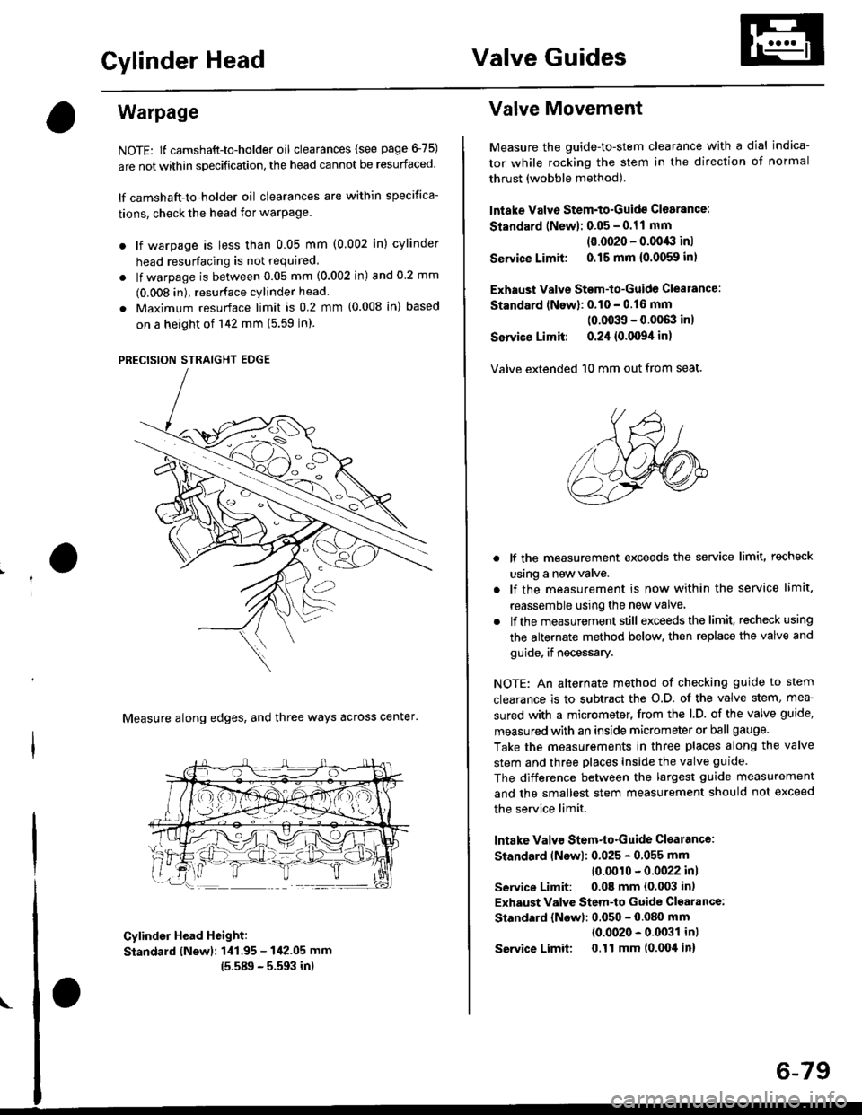
Warpage
NOTE: lf camshaft-to-holder oil clearances (see page 475)
are not within specification, the head cannot be resurfaced.
lf camshaft-to-holder oil clearances are within specifica-
tions, check the head for warPage.
. lf warpage is less than 0.05 mm (0.002 in) cylinder
head resurfacing is not required.
. lf warpage is between 0.05 mm (0.002 in) and 0 2 mm
(0.008 in), resurface cylinder head
. Maximum resurface limit is 0.2 mm (0.008 in) based
on a height of 142 mm (5.59 in).
PRECISION STRAIGHT EDGE
Measure along edges, and three ways across center'
Cylinder Head Height:
Standard lNewl: 1i11.95 - 142.05 mm
15.589 - 5.593 in)
Valve Movement
Measure the guide-to-stem clearance with a dial indica-
tor while rocking the stem in the direction of normal
thrust (wobble method).
lntake Valve Stem-to-Guide Cl6arance:
Standard (Newl: 0.05 - 0.11 mm
(0.0020 - 0.0043 inl
Service Limit: 0.15 mm {0.0059 inl
Exhaust Valve Stem-to-Guide Clealance:
Standard lNewl: 0.10 - 0.16 mm
(0.0039 - 0.0063 inl
Service Limit: 0.24 {0.0094 in)
Valve extended 10 mm out from seat.
lf the measurement exceeds the service limit, recheck
using a new valve.
lf the measurement is now within the service limit.
reassemble using the new valve
lf the measurement still exceeds the limit. recheck using
the alternate method below. then replace the valve and
guide, if necessary.
NOTE: An alternate method of checking guide to stem
clearance is to subtract the o.D. of the valve stem, mea-
sured with a micrometer, from the l.D. of the valve guide,
measured with an inside micrometer or ball gauge.
Take the measurements in three places along the valve
stem and three places inside the valve guide.
The difference between the largest guide measurement
and the smallest stem measurement should not exceed
the service limit.
lntake Valv€ Stem-to-Guide Clsarance:
Standard lNswl: 0.025 - 0.055 mm
10.0010 - 0.0022 inl
service Limit: 0.08 mm (0.003 in)
Exhaust Valve Stem-to Guide Cl€arance:
Standard {Newl: 0.050 - 0.080 mm
{0.0020 - 0.0031 inl
Service Limit 0.ll mm (0.004 in)
6-79
Page 191 of 2189

7. Apply a thin coat of clean engine oil to the outside
of the new valve guide. Install the guide from the
camshaft side of the head; use the special tool to
drive the guide in to the specified installed height. lf
you have all l6 guides to do, you may have to reheat
the head,
VALVE GUIDE DRIVER,5.5 mm077i12 - (x)l01(x)
tr A\
Valve Guide Installed Hoight:
lntake: 12.55 - 13.05 mm {0.,194 - 0.514 in)
Exhaust: 12.55 - 13.05 mm 10.494 - 0.51'l in)
VALVE GUIDE
\
Reaming
NOTE: For new valve guides onlY.
1. Coat both reamer and valve guide with cufting oil.
2. Rotate the reamer clockwise the full length of the
valve guide bore.
Continue to rotate the reamer clockwise while
removing it from the bore
Thoroughly wash the guide in detergent and water
to remove any cutting residue.
Check clearance with a valve lsee page 6-73)
. Verify that the valve slides in the intake and
exhaust valve guides without exertlng pressure.
REAMER HANDLE
Turn r6amer in
clockwise direction
a
VALVE GUIOE REAMER. 5.5 mm
OTHAH - PJTO1IIB
6-81
Page 192 of 2189

Valves
1.
Installation
Coat the valve stems with oil. lnsert the valves into
the valve guides.
NOTE: Check that the valves move up and downsmoothly.
Installthe spring seats on the cylinder head.
Install the valve seals using the special tool.
NOTE: Exhaust and intake valve seals are not inter-
changeable.
WHITESPRING
VALVE GUIDE SEAL INSTALLERKD-28)g (Commercially available)NOTE: Use small lDend of tool,
2.
BRACKSPRING
VALVE SEALReplace.
tNsTALLERVALVE GUIDE SEALKD-2899NOTE: Use small lDend of tool
(
4. lnstall the valve spring and valve retainer, theninstall the valve spring compressor. Compress thespring, and install the valve keepers.
NOTE: Place the end of the valve spring with closely
wound coils toward the cylinder head.
VALVE SpRtNG VALVE SPRTNG
COMpRESSOR COMPRESSORATTACHMENT
ATTACHMENT EXTENSTON
0775? _ pJlOl0A o?MAF - PR9010A
VALVE SPRING COMPRESSORlCommercially available)Snap-on CF711 or KD-3tXlwith #32JAWSLightly tap the end of each valve stem two or threetimes with the wooden handle of a hammer to ensureproper seating of the valve and valve keepers.
NOTE: Tap the valve stem only along its axis soyou do not bend the stem.
I
5.
Page 196 of 2189

Cylinder Head
Installation (cont'dl
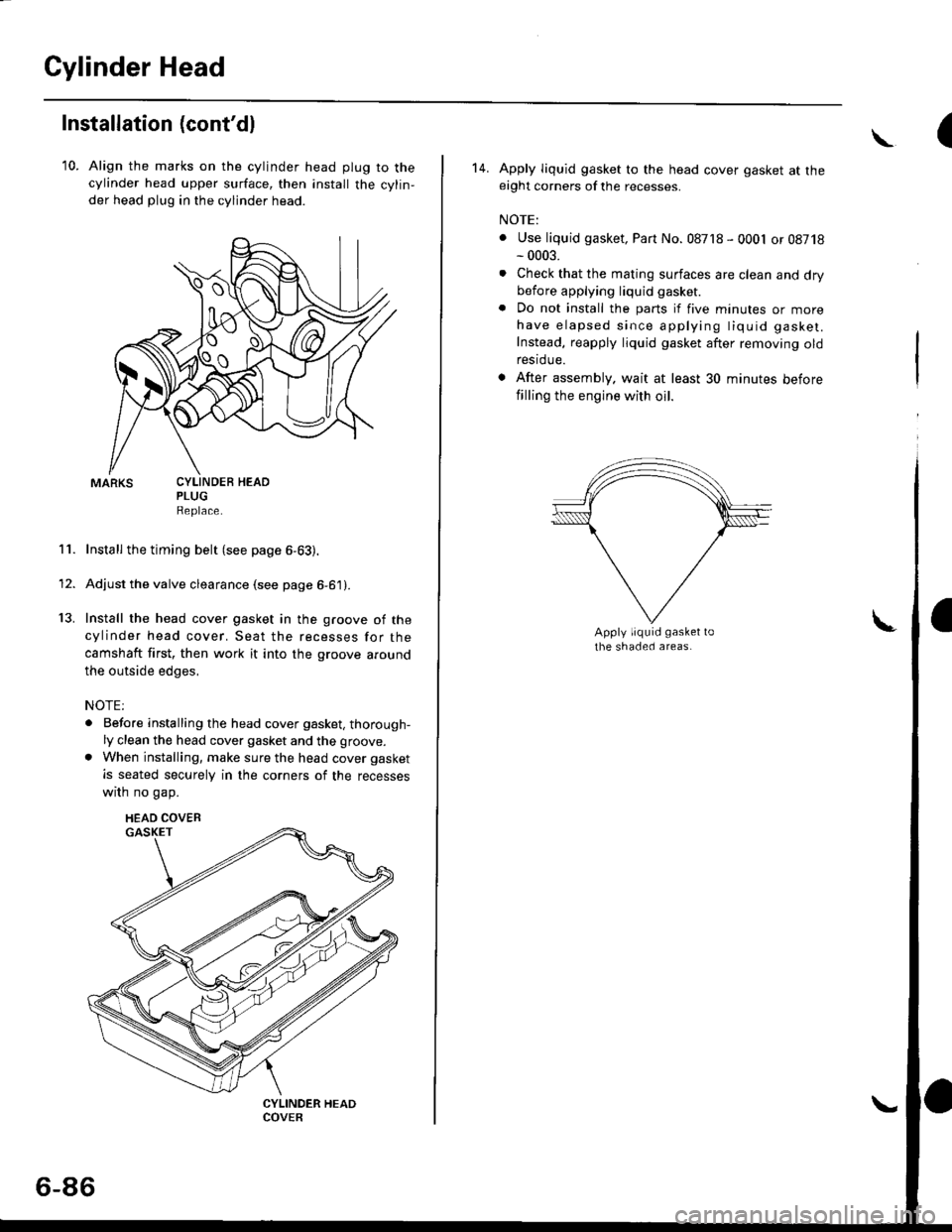
10. Align the marks on the cylinder head plug to thecylinder head upper surface, then install the cylin,
der head plug in the cylinder head.
PLUGReplace.
Install the timing belt (see page 6-63).
Adjust the valve clearance (see page 6-61).
Install the head cover gasket in the groove of the
cylinder head cover. Seat the recesses for the
camshaft first, then work it into the groove around
the outside edges,
NOTE:
. Before installing the head cover gasket, thorough-ly clean the head cover gasket and the groove.
. When installing, make sure the head cover gasket
is seated securely in the corners of the recesses
wrrn no gap.
11.
13.
1'
CYLINDEB HEAD
HEAD COVEB
6-86
(\
14. Apply liquid gasket to the head cover gasket at theeight corners of the recesses.
NOTE:
. Use liquid gasket, Part No. 08718 - 0001 or 08718- 0003.
. Check that the mating surfaces are clean and drybefore applying liquid gasket
. Do not install the parts if five minutes or morehave elapsed since applying tiquid gasket.
Instead, reapply liquid gasket after removing oldrestdue.
. After assembly. wait at least 30 minutes before
filling the engine with oil.
Page 197 of 2189
15. When installing the cylinder head cover, hold the
head cover gasket in the groove by placing your fin-
gers on the camshaft holder contacting surfaces
(toD of the semicircles).
Once the cylinder head cover is on the cylinder
head, slide the cover slightly back and forth to seat
the head cover gasket.
NOTE:
. Be{ore installing the cylinder head cover, clean
the cvlinder head contacting surfaces using a
shoP towel.
. Oo not touch the parts where liquid gasket was
applied.
. Replace any washer taht is damaged or deter'o-
rated.
t
\
6-A7
16. Tighten the nuts in two or three steps. In the final
step, tighten all nuts, in sequence, to 9 8 N'm {1 0
kgf.m, 7.2 lbf.ft).
NOTE: After assembly, wait at least 30 minutes
before filling the engine with oil.
After installing, check that all tubes' hoses and con-
nectors are installed correctly.17.
Page 200 of 2189

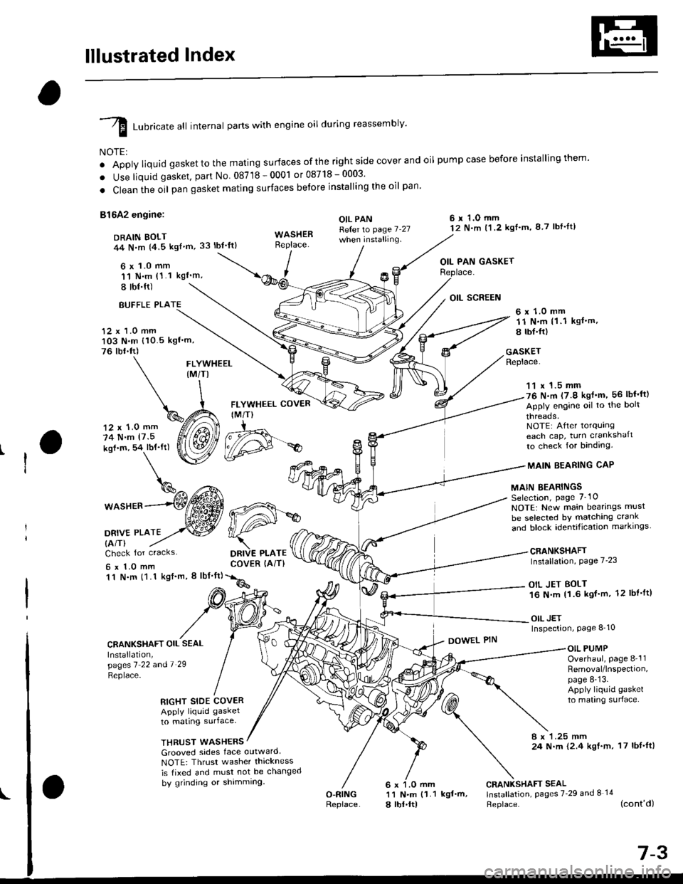
lllustrated Index
I runricate att internal parts with engine oil during reassembly'
NOTE:
o Apply liquid gaskettothe mating surfaces ofthe right side cover and oil pumpcase before installingthem'
. Use liquid gasket, part No 08718-0001 or08718-0003'
. Clean the oil pan gasket mating surfaces betore installing the oil pan
81642 engine:
DRAIN BOLT44 N,m {4.5 kgf'm,33 lbt'ft)
6 x 1.0 mm'11 N.m (1.1 kgI'm,
I tbl.ft)
OIL PANReter to page 7 27when installing.
6 r 1.O mm12 N.m t1.2 kgl'm, 8 7 lbf'lt)
OIL PAN GASKET
BUFFLE PLA
12 x 1.0 mm103 N.m {10.5 kgf'm,
76 tbr.ft)
6 x 1.0 mm11 N.m (1 .1 kgf.m,
8 tbI.fr)
GASKETReplace.FLYWHEEL(M/TI
12 x 1.0 mm
74 N.m (7.5
kof.m, 54 lbf'ft)
1^c{Eb\%^ t*^
*o"rr^--(Wffi
oa*,trto2,.w
FLYWHEEL COVER
IM/T)
DRIVE PLATECOVER (AiT)
11 x 1.5 mm76 N.m (7.9 kgf'm, 56 lbf'ft)
Apply engine oil to the bolt
threads.NOTE: After torqurngeach cap, turn crankshaft
to check for binding.
MAIN EEARING CAP
MAIN BEARINGSSelection, page 7_10
NOTE: New main bearings musl
be selected bY matching crank
and block identification markrngs
CRANKSHAFTInstallation, Page 7'23
OIL JET BOLT16 N.m 11.6 kgf'm, 12 lbl'ft)
OIL JETInspection, Page 8_10
Check for cracks
6x1.0mm11 N.m {1.1 kgf'm, I lbf'ft}
CRANKSHAFT OIL SEAL
Installation,pagesl 22 andl 29
Replace-
DOWEL PINOIL PUMPOverhaul, page 8-'l1Removal/lnspection,page 8-13.Apply liquid gasket
to mating surlace.RIGHT SIDE COVERApply liquid gasket
to mating surface.
THRUST WASHERS8 x 1.25 mm24 N.m {2.4 kgf.m, 17 lbf'ft)Grooved sides face outward
NOTE: Thrusr washer thickness
is tixed and must not be changed
by grinding or shimming
O-RINGReplace
CRANKSHAFT SEAL11 N.m {1.1 kgf'm, lnstallation, pages 7'29 and I 14
a lbt.ltl Heplace. (cont'd)
d#*
Page 201 of 2189

lllustrated Index
(cont'dl
I Luoricate att internal parts with engine oil during reassembly.
NOTE:
' Apply liquid gasket to the mating surfaces ofthe rightside coverand oil pumpcase before installingthem.. Use liquid gasket, part No. 08718 - 0001 or 087,18 _ OOO3.. Clean the oil pan gasket mating surfaces before installing it.
D16Y7 engine:6 x 1.0 mm12 N.m (1.2 kgt.m.8.7 tbf.tr)DRAIN BOLT44 N.m {4.5 kgt.m.33 tbt.ttl
,(
I
I
OIL PAN GASKETFLYWHEEL COVERIM/T)6x 1.0 mm12 N.m ('l .2 kgt.m, 8.7 tbt.trl
OIL PANRefer to page 7-27
Apply liquid gasker tothese points.
Replace.
WASHERReplace.12 x '1.0 mm118 N.m{12.0 kgt.m, 87 tbf.tr}
11 x 1.5 mm51 N.m15.2 kgl.m,38lbtftl
Apply engine oilto the boltthreads.NOTE: After torquingeach cap, turn the crankshaftto check for binding.
MAIN BEARINGSSelection, page 7-10
MAIN BEARING CAP
CRANKSHAFTInstallation, page 7 23
NOTE: New main bearings mustbe selected by matching crankand block identification markings.
6 r 1.0 mm11 N.m {1.1
6 x 1.0 mm11 N.m 11.1
ksI.m, 8 lbt.ft)
OIL SCREEN
kgt.m, 8 lbf.trl
Check for cracks.
CRANKSHAFT OIL SEALInstallation,pages 1 22 a^d 7-29
\:eprace'
GASKETReplace.
6 x 1.O mm11 N.m {1.1 kgt.m,8 rbt.frl
RIGHT SIDE COVERApply liquid gasker1o matrng surface,
OIL PUMPOverhaul, page 8-12Bemoval/lnspection,page 8-13
DOWEL PIN
WASHERSGrooved sides face outward.NOTE: Thrust washer thicknessis fixed and must not be changedby grinding or shimming.
CRANKSHAFT SEAL
l.j"Ji:l"^ pages z.2e --.S)
Replace.
6 x 1.0 mm11 N.m {1.18 tbt.fr)
7-4
BREATHING PORT COVERMOUNT BOLTS6 x 1.0 mm11 N.m {1.1 kgt.m, 8 tbf.fr}Apply liquid gasker tothe boh threads.
DOWEL PIN