1998 HONDA CIVIC ad blue
[x] Cancel search: ad bluePage 1825 of 2189
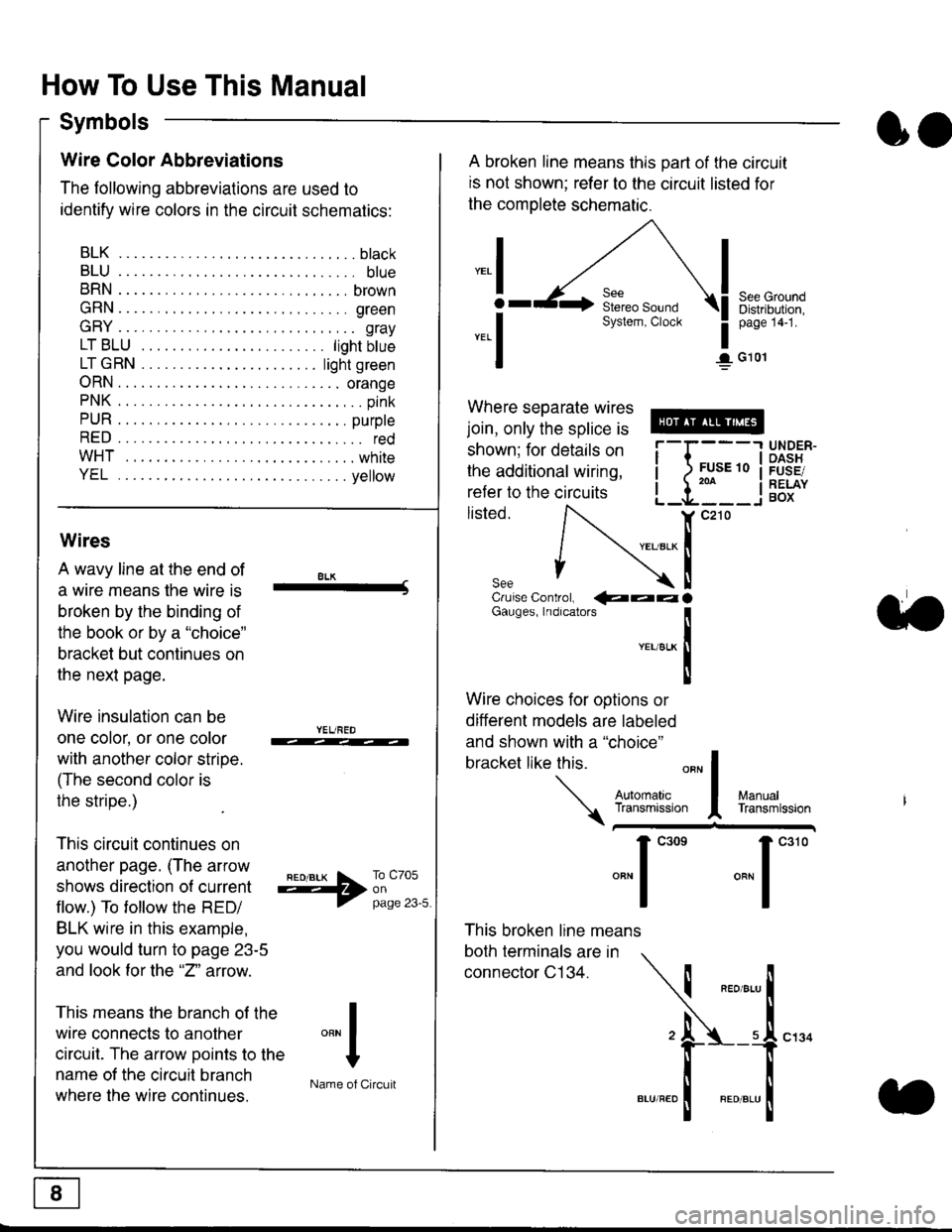
How To Use This Manual
Symbols
oo
Wire Color Abbreviations
The following abbreviations are used to
identify wire colors in the circuit schematics:
BLK.... .........b|ack
BLU.... ......... blue
BRN.... ,....... brown
GRN.... ........ green
GRY.... ......,.. gray
LTBLU . .....lightbtue
LTGRN. ....lightgreen
ORN.... ....... orange
PNK .... .......,.. pink
PUR .... ........ purple
RED .... .......... red
WHT... .........white
YEL .... ........ yellow
A broken line means this part of the circuit
is not shown; refer to the circuit listed for
the complete schematic.
"ral
o
-.1
See GroundDistribution,page 141.
I G101
Where separate wires
join, only the splice is
shown; for details on
the additional wiring,
refer to the circuits
listed.ili::i
{[
UNDER-OASHFUSE/RELAYBOX
Wires
A wavy line at the end of
a wire means lhe wire is
broken by the binding of
the book or by a "choice"
bracket but continues on
the next page.
Wire insulation can be
one color, or one color
with another color stripe.
(The second color is
the stripe.)
This circuit continues on
another page. (The arrow
shows direction o{ current
flow.) To tollow the RED/
BLK wire in this example,
you would turn to page 23-5
and look for the "2" anow.
This means the branch of the
wire connects to another
circuit. The arrow Doints to the
name of the circuit branch
where the wire continues.
8LK-Cruise Control, €�aaaGauges, Indrcalors
!YEUsLK
Ttl
Wire choices for options or
different models are labeled
and shown with a "choice"
bracket like this.
This broken line means
both terminals are in
connector C134.
a.
+##l:i""lManuallransmission
ryil;::,
.""1
""'
"""1".'0
I
""^l
:-lName of Circuit
Page 2109 of 2189
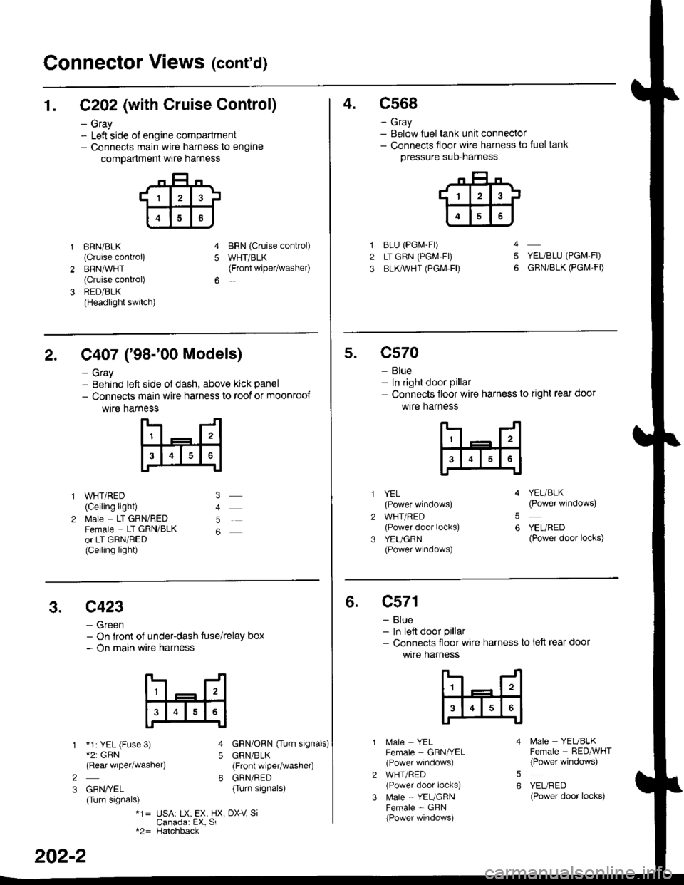
Connector Views (cont'd)
1. C202 (with Cruise Control)
- Gray- Left side ol engine compartment- Connects main wire harness to engine
compartment wre harness
gRN/BLK
(Cruise control)
BRN,ryVHT(Cruise control)
RED/BLK(Headlight switch)
BRN {Cruise conkol)
WHT/BLK(Front wipetwashel)5
4.c568
- Gray- Below Juel tank unit connector- Connects floor wire harness to tuel tank
pressure suo-narness
BLU (PGi.4-Fr)
LT GRN (PGM-FI)
BLl(WHT (PGI\4-FD
YEUBLU (PGM,FI)
GRN/BLK (PGI\,4.FD
4
5
2. C407 ('98-'00 Models)
- Gray- Behind left side ol dash, above kick panel
- Connects main wire harness to roof or moonroo{
wtre harness
WHT/RED(Ceiling light)
l\4ale - LT GRN/REDFemale - LT GRN/BLKor LT GRN/RED(Ceiling light)
5
5.c570
- Blue- In right door pillar- Connects floor wire harness to right rear door
wlre hafness
2
3
YEL(Power windows)
WHT/RED(Power door locks)
YEUGRN(Power wrndows)
YEL/BLK(Power windows)
YEURED(Power door locks)
5
6
3.c423
- Green- On Jront of under-dash tuse/relay box- On main wire harness
*1: YEL (Fuse 3)*2: GRN(Rear wiper/washe4
GRN/YEL(Turn signals)
GRN/ORN {Tu.n signals)
GRN/BLK(Front wiper/washer)
GRN/RED(Turn signals)
5
62
3
*1= USA: tX, EX, HX, DX-V SiCanada: EX, Si*2= Hatchback
202-2
6.c571
- Blue- In lett door pillar- Connects floor wire harness to lett rear door
wlre harness
MaIe _ YELFemale - GBN/YEL(Power windows)
WHT/RED(Power door locks)
Male - YEUGRNFemale - GBN(Power windows)
5
6
N4ale YEUBLKFemale - RED,ryVHT(Power windows)
YEURED(Power door locks)
Page 2110 of 2189
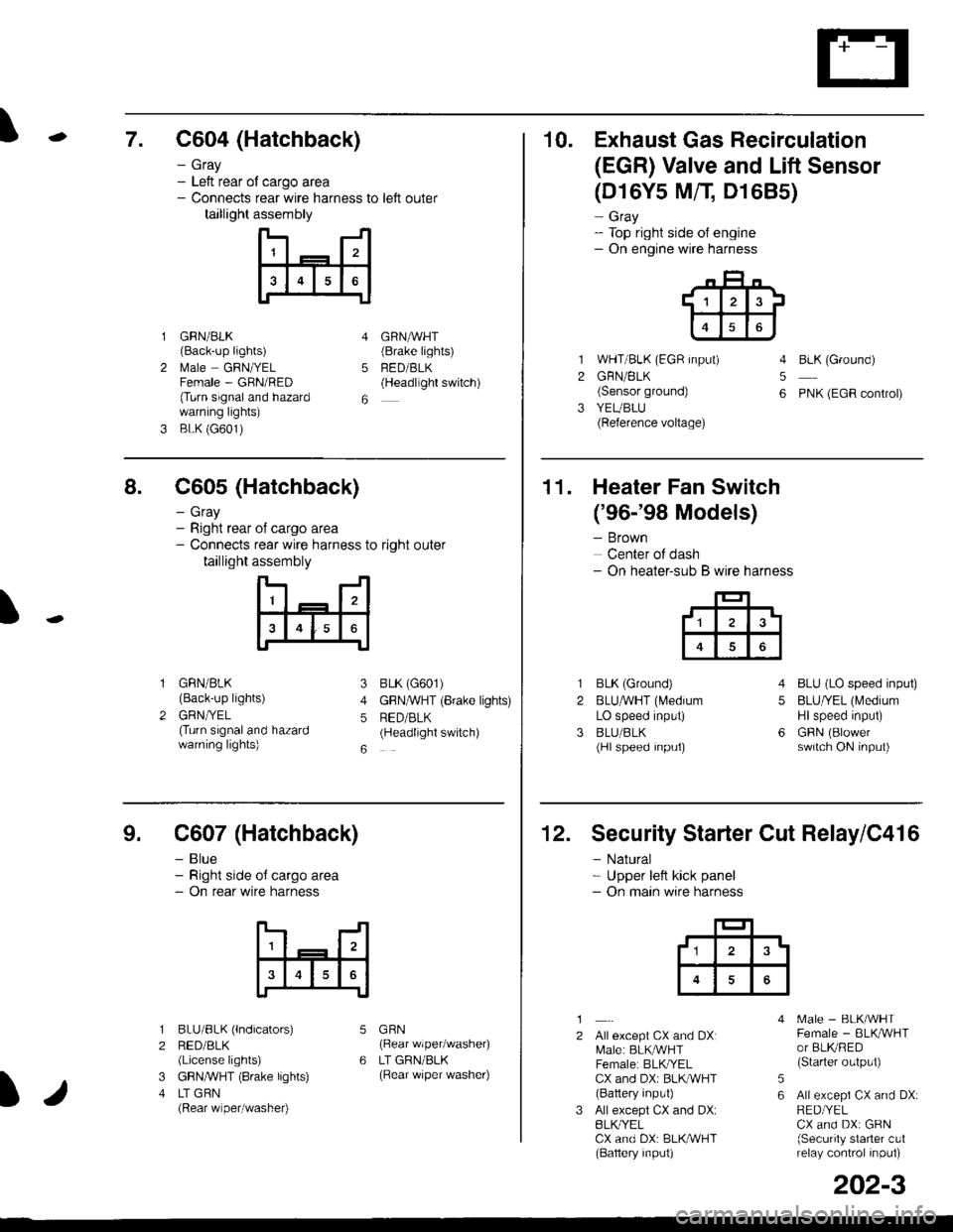
\7. C604 (Hatchback)
GRN/BLK(Back-up lights)
l\4ale GRNIYELFemale - GRN/RED(Turn signaland hazardwarning lights)
BLK (G601)
- Gray- Left rear ol cargo area- Connects rear wire harness to left outer
taillight assembly
4
5
6
1
2
GRNAVHT(Brake lights)
FED/BLK(Headllght switch)
10. Exhaust Gas Recirculation
(EGR) Valve and Lift Sensor
1
2
3
(D16Y5 MfI D1685)
- Gray- Top right side of engine- On engine wire harness
WHT/BLK (EGR input)
GRN/BLK(Sensor ground)
YEUBLU(Reference voltage)
4
5
6
BLK (Ground)
PNK (EGR control)
of cargo area
rear wire harness to right outer
assembly
n- -n
a t | _ a2a
l3I4t5tttl
IJ
I
8. C605 (Hatchback)
- Gray- Right rear- Connects
taillight
GRN/BLK(Back-up lights)
GRNTYEL(Turn signaland hazardwarning lights)
3
4
5
6
1
2
BLK (G601)
GFNAVHT (Brake lights)
RED/BLK(Headlight switch)
11. Heater Fan Switch
('96-'98 Models)
- Brown
Center of dash- On heater-sub B wire harness
BLK (Ground)
BLUAVHT (L4edium
LO speed input)
BLU/BLK(Hl speed input)
4
5
6
1
2
3
BLU (LO speed input)
BLU/YEL (Medium
Hlspeed input)
GFIN (Blowerswitch ON input)
9. C607 (Hatchback)
- Blue- Right side o{ cargo area- On rear wire harness
BLU/BLK (lndicators)
RED/BLK(License lights)
GBN,ryVHT (8rake lights)
LT GBN(Rear wiper/washe0
5
6
1
2
3
4
GRN(Rear wiper/washer)
LT GRN/BLK(Rear \/iper washer)
)/
202-3
12. Security Starter Cut Relay/C416
- Natural* Upper left kick panel- On main wire harness
1
2Allexcept CX and DXI[,4ale: BLK,^r'r'HTFemale: BLKI/ELCX and DXi BLI(WHT(Battery input)
All except CX and DX:BLK^/ELCX and DX: BLK/WHT(Baftery input)
[.4ale - BLK/WHTFemale - BLKAVHTor BLKRED(Starter output)
All excepi CX and DX:RED/YELCX and DX: GRN(Security starter c!1relay control inpul)
5
6
tl3'
Page 2115 of 2189
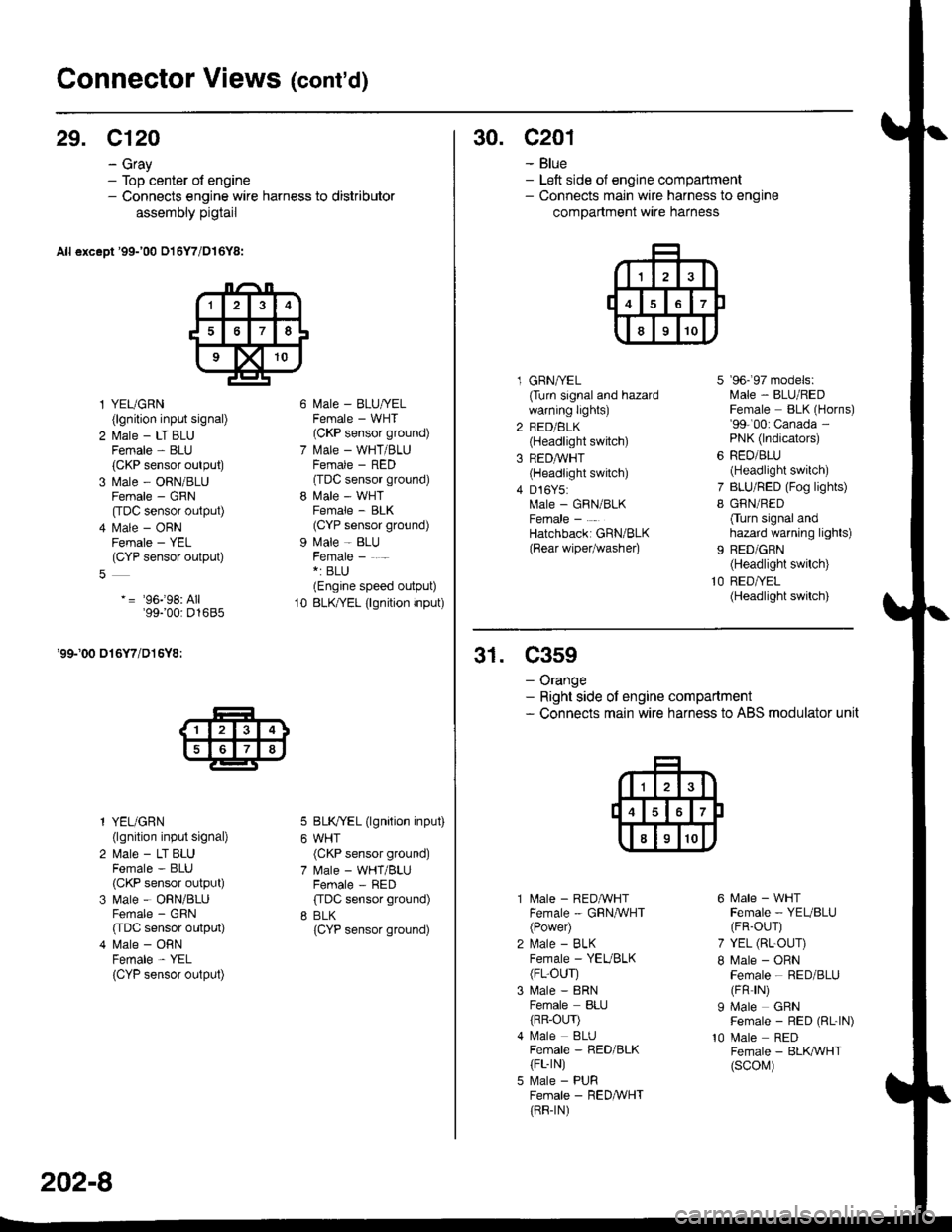
Connector Views (cont'd)
29. C120
- Gray- Top center of engine- Connects engine wire harness to distributor
assembly pigtail
All except '99-'00 016Y7/D16Y8:
l YEUGRN(lgnition input signal)
2 l\.4ale - LT BLUFemale - BLU(CKP sensor output)
3 Male - ORN/BLUFemale - GRN
[tDC sensor output)
4 l\.4ale - ORNFemale - YEL(CYP sensor output)
-= '96j98: All'99100: D1685
'99-'00 016Y7/D16Y8:
l YEUGRN(lgnition input signal)
2 Male - LT BLUFemale - BLU(CKP sensor output)
3 Male - ORN/BLUFemale - GRN
CIDC sensor output)
4 Male - ORNFemale - YEL
{CYP sensor output)
l\4ale - BLU/YELFemale - WHT(CKP sensor ground)
l\.4ale - WHT/BLUFCMAIE _ HtsL'(TDC sensor ground)
l\4ale - WHTFemale - BLK(CYP sensor ground)
Male - BLUFemale - . -*: BLU(Engine speed output)
BLK/YEL (lgnition input)
BLK/YEL (lgnition input)
WHT(CKP sensor ground)
Male - WHT/BLUFemale - RED
ffDC sensor ground)
BLK(CYP sensor ground)
10
202-8
30. c201
- Blue- Left side of engine compartment- Connects main wire harness to engine
compartment wire harness
l GRNA/EL(Turn signal and hazardwarning lights)
2 RED/BLK(Headlight switch)
3 REDAVHT(Headlight switch)
4 D16Y5:Male - GRN/BLKFemale -
Hatchbacki GRN/BLK
{Bear wipetwashe0
7
I
9b- 9/ mooets:lvlale - BLU/REDFemale BLK (Horns)'99-'00: Canada -
PNK (lndicators)
RED/BLU(Headlight switch)
BLU/RED (Fog lights)
GRN/RED
Cturn signal andhazard warning lights)
BED/GRN(Headlight switch)
RED/YEL(Headlight switch)
31. C359
- Orange- Right side ot engine compartment- Connects main wire harness to ABS modulator unit
10
l\4ale - REDAVHTFemale - GRNA/VHT(Power)
l\,4ale - BLKFemale - YEVBLK(FL-OUr)
Male - 8RNFemale BLIJ
{RR-OLrr)l\4ale BLUFemale - RED/BLK(FL-rN)
Male - PURFemale - RED&VHT(RR-rN)
6 Male - WHTFemale - YEUBLU(FR-OUr)
7 YEL (RL-OUr)
I Male - ORNFemale - RED/BLU(FR rN)
I Male GRNFemale - RED (RL-|N)
10 Male REDFemale - BLK,ryVHT(scol\,1)
Page 2117 of 2189
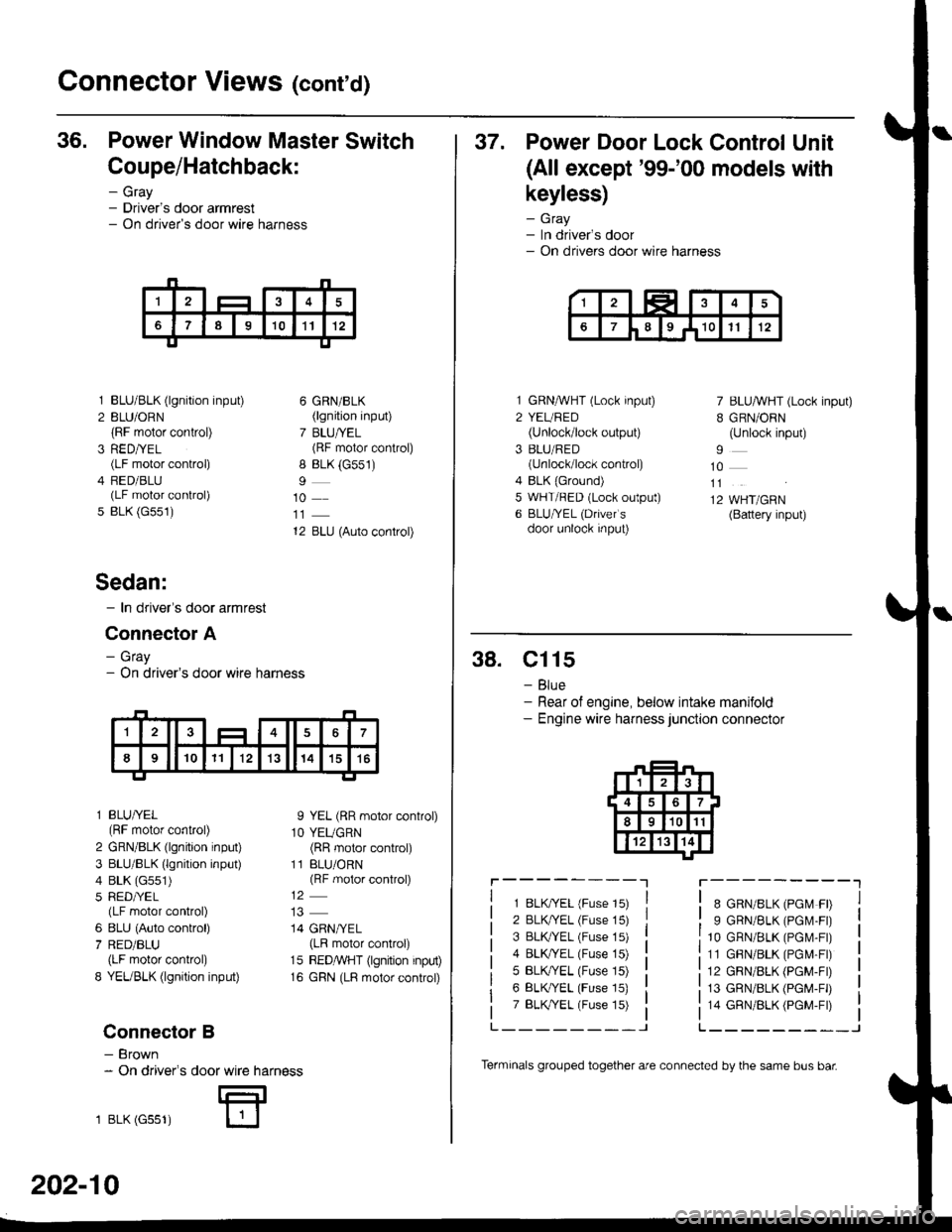
Connector Views (cont'd)
36. Power Window Master Switch
Coupe/Hatchback:
- Gray- Driver's door armrest- On driver's door wire harness
3
5
BLU/BLK (lgnition input)
BLU/ORN(RF motor control)
RED/YEL(LF motor control)
FED/BLU(LF motor control)
BLK (G551)
6 GRN/BLK(lgnition input)
7 BLU/YEL(RF motor control)
8 BLK (G551)
10
12 BLU (Auto control)
I YEL (RR motor control)
1O YEUGRN(RR motor control)
11 BLU/ORN(RF motor control)
14 GRN/YEL(LR motor control)
15 REDMHT (lgnition input)
16 GRN (LR motor control)
Sedan:
- In driver's door armrest
Connector A
- Gray- On driver's door wire harness
l BLU/YEL(RF motor control)
2 GRN/BLK (lgnition input)
3 BLU/BLK (lgnition input)
4 BLK (G551)
5 RED/YEL(LF motor control)
6 8LU (Auto control)
7 RED/BLU(LF motor control)
8 YEUBLK (lgnition input)
Connector B
- Brown- On driver's
1 BLK (Gss1)
door wire harness
E
202-10
Terminals grouped together are connected by the same bus bar
37. Power Door Lock Control Unit
(All except'99-'00 models with
keyless)
- Gray- In driver's door- On drivers door wire harness
1 GRNMHT (Lock input)
2 YEURED(Unlock/lock output)
3 BLU/RED(unlock/lock control)
4 BLK {Ground)5 WHT/RED (Lock output)
6 BLU/YEL (Drivefs
door unlock input)
7 BLU/WHT (Lock input)
B GRN/ORN(Unlock input)
10
11
12 WHT/GRN(Battery input)
38. Cl15
- Blue- Rear of engine, below intake manifold- Engine wire harness junction connector
r----------lr---------"1
1 8LK?ryEL (Fuse 15)
2 BLK/YEL (Fuse 15)
3 BLK TEL (Fuse 15)
4 BLK/YEL (Fuse 15)
5 BLK,/YEL (Fuse 15)
6 BLK/YEL (Fuse 15)
7 BLK,TYEL (Fuse 15)
8 GRN/8LK (PGM FD
9 GRN/BLK (PGM.FD
10 GRN/BLK (PGr\,4-Fr)
11 GBN/BLK (PGM-Fr)
12 GRN/BLK (PGM-FD
13 GRN/BLK (PGM-FD
14 GRN/BLK (PGM-Fr)
L_______-JL______--_J
Page 2120 of 2189
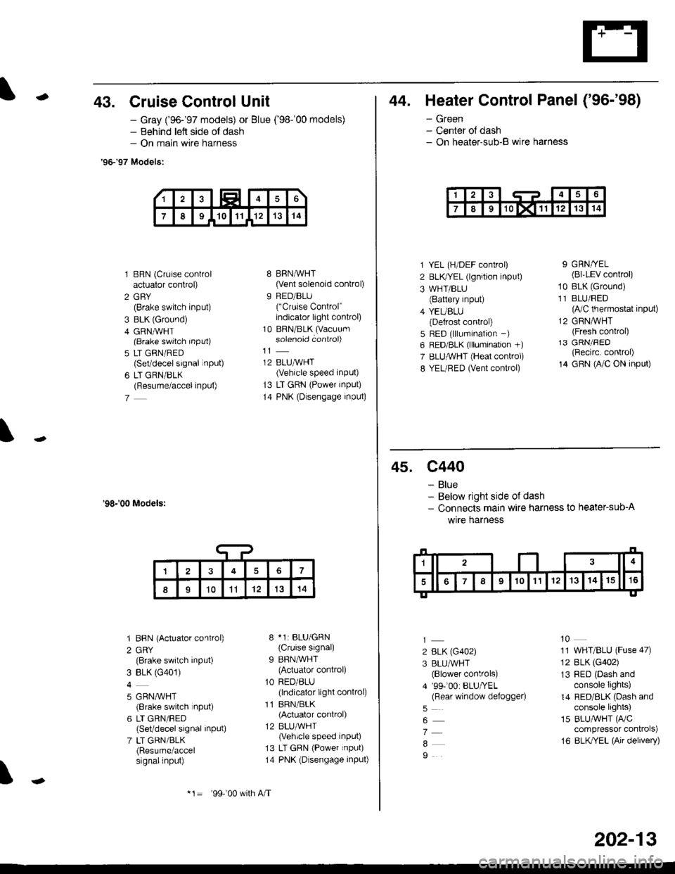
-43. Cruise Control Unit
- Gray ('96-'97 models) or Blue ('98-'00 models)- Behind lett side ol dash- On main wire harness
'96-'97 Models:
1 BRN (Cruise controlactuator control)
2 GBY(Brake switch input)
3 BLK (Ground)
4 GRN,ryVHT(Brake switch Input)
5 LT GRN/RED(Set/decel signal inPUt)
6 LT GRN/BLK(Resume/accel inPut)
7
'98-'00 Models:
'I BBN (Actuator control)
2 GRY(Brake switch input)
3 BLK (G401)
4
5 GRN,^/VHT(8rake switch rnput)
6 LT GRN/RED(Set/decel signal inPut)
7 LT GRN/BLK(Resume/accelsignalinput)
8 BRN,AiVHT(Vent solenoid control)
9 RED/BLU("Cruise Control"indicator light conkol)
10 BRN/BLK (Vacuum
solenoid controi)
12 BLUMHT(Vehicle speed input)
13 LT GRN (Power input)
14 PNK (Dlsengage input)
8 *1: BLU/GRN(Cruise signal)
9 BFN/WHT
{Actuator control)
1O RED/ALU(lndicator light conkol)
11 BRN/BLK(Actuator control)
12 BLU,ryVHT(Vehicle speed input)
13 LT GRN (Power input)
14 PNK (Dlsengage input)
\
17
II1011'121314
*1= 99-'00 w(h A/T
202-13
44. Heater Control Panel ('96-'98)
- Green- Center ol dash- On heater-sub-B wire harness
1 YEL (H/DEF control)
2 BLKTYEL (lgnition input)
3 WHT/BLU(Battery input)
4 YEUBLU(Defrost control)
5 RED (lllumination -)
6 RED/BLK (lllumination +)
7 ELUruVHT (Heat conkol)
8 YEL/RED (Vent control)
9 GRN/YEL(Bl'LEV control)
10 BLK (Ground)
11 BLU/FED(lVC thermostat input)
12 GRNMHT(Fresh control)13 GRN/FED(Recirc. control)
14 GRN (A/C ON input)
45. c440
- Blue- Below right side of dash- Connects main wire harness to heater-sub-A
wrre narness
2 BLK (G402)
3 BLU/WHT(Blower controls)
4 '99-'00: BLU/YEL(Rear window defoggeo
7
9
10
11 WHT/BLU (Fuse 47)
12 BLK (G402)
13 RED (Dash andconsole Iights)
14 RED/BLK (Dash andconsole lights)
15 BLUAVHT (FVC
compressor conkols)
16 BLK/YEL (Air delivery)
Page 2121 of 2189
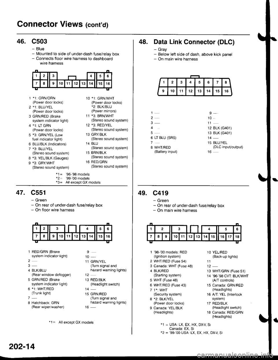
Gonnector Views (conrd)
46. C503
B
9
*1: GBN/ORN(Power door locks)*1r BLU|/EL(Power door locks)
GRN/RED (Brake
system indicator light)*1r LT GRN(Power door locks)*3: GRN/YEL (Lowfuel indicator light)
BLU/BLK (lndicators)*3: BLU/YEL(Stereo sound system)*3: YEUBLK (Gauges)*3: GRY/WHT(Stereo sound system)
10 *1: GRNAVHT(Power door locks)*2: BL(BLU(Power mirfors)
11 *3: BRNMHT(Stereo sound system)
12 *3: RED/YEL(Stereo sound system)
13 GRY/BLK(Stereo sound system)
14 BLU(Stereo sound system)
15 BRN/BLK(Stereo sound system)
16 RED/GBN(Stereo sound system)
- Blue- lvlounted to side of under-dash fuse/relay box- Connects floor wire harness to dashboardwtre narness
1
2
3
5
6
7
*1= '96-'98 models*2: '99-'00 models*3= All except GX models
48. Data Link Connector (DLC)
- Gray- Below left side of dash, above kick panel- On main wire harness
4
6 LT BLU (SRS)
7
8 WHT/BED(Battery input)
9
10
12 BLK (G401)
13 BLK (G401)
14
15 BLU/YEL(DLC inpuVoutput)
47. C551
- Green- On rear of under-dash tuse/relay box- On floor wire harness
1 BED/GRN (Brake
system indicator light)
2
4 BLI(BLU(Rear window defogger)
5 GBN/RED (Brake
system indicator llght)
6 *1: WHT/RED(Trunk light)
7
8 Hatchback: GBN(Rear wiper/washer)
9
10
11 GRN/YEL(Turn signal andhazard warning lights)
13 RED/BLK(Headlight switch)
14
15 GRN/RED(Turn signal andhazard warning lights)
202-14
*1= Allexcept GX models
49. C419
- Green- On rear of under-dash fuse/relay box- On main wire harness
1 '98''00 models: RED(lgnition system)
2 WHT/RED (Fuse s4)
3 Canada: WHT (Fuse 48)
4 BLI(RED(Starting system)
5 WHT (Fuse 48)
6 WHT/RED (Fuse 43)
7 1*: WHT(Security system)
I *2: BLK,TYEL
{Power door locks)
I Canada: YEL/BLK(Headlights)
1O YEURED(Back up lights)
11
13 WHT/GRN (Fuse 51)
14 '96-'98 CVT: BLKWHT(A/T controls)
15 Canada: GRN/RED(Headlights)
16 A/Ti YEL (lnterlock
system)
17 RED/BLK(Headlight switch)
18 Canada: RED/GRN(Headlights)
"1 = USA: LX, EX, HX, DX-V SiCanada: EX, Si12 = '99100 USA: LX, EX, HX, DX-V Si
Page 2123 of 2189
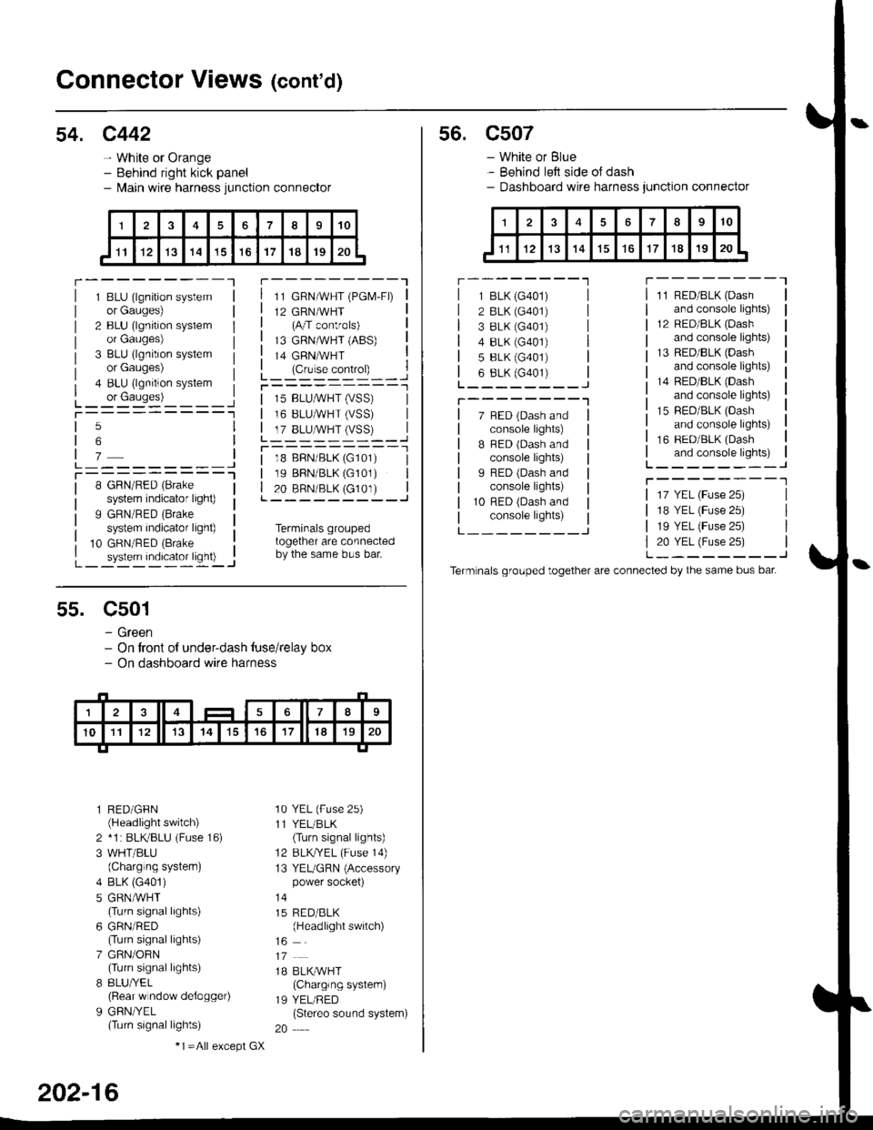
Connector Views (cont'd)
54. c442
- White or Orange- Behind right kick panel- l\,lain wire harness junction connector
r---------Tr---------"1
1 BLU (lgnition systemor Gauges)
2 BLU (lgnition syslemor Gauges)
3 BLU (lgnition systemor Gauges)
4 BLU (lgnition system
L_ or causes)L_-:-:::'-'�____Jt-----------1
11 GRN/WHT (PGM-FD
12 GRN/WHT(A/T controls)
13 GRNMHT (ABS)
14 GRNMHT
L_ lc,r'." .oIr"D_ _ _.jr----------_l
5
6
7L---------JT----------l8 GRN/RED (Brake
system indicator light)
9 GRN/RED (Brake
system indicator light)
10 GRN/RED (Brake
_ system indicator ligh0 -..1
| 15 BLUMHT (vSS) |I 16 BLUMHT (VSS) I
L T?_BLUSTrySS)--..]
l--------- - -l
| 18 BFN/BLK (G101) I| 19 BBN/BLK (G101) || 20 BRN/BLK (c101) |L---------J
Terminals groupedtogether are connectedby the same bus bar.
55. C501
- Green- On tront of under-dash tuse/relay box- On dashboard wire harness
l RED/GFN(Headlight switch)
2 *1 : BLKBLU (Fuse 16)
3 WHT/BLU(Charging systern)
4 BLK (G401)
5 GRNMHT(Turn signal lights)
6 GRN/RED(Turn signal lights)
7 GRN/ORN(Turn signal lights)
8 8LU/YEL(Rear w ndow delogger)
9 GFN/YEL(Turn signal lights)
'10 YEL (Fuse 25)
11 YEL/BLK(Turn signal lights)
12 BLKTYEL (Fuse 14)
13 YEUGRN (Accessorypower socket)
15 RED/BLK(Headlight switch)
1B BLK/WHT(Charglng system)
19 YEL/RED(Stereo sound system)
20
202-16
-1 =All e),cept GX
s6. c507
- White or Blue- Behind left side oJ dash- Dashboard wire harness junction connector
r --------'lT---------l
7 BED (Dash andconsole lights)
B BED (Dash andconsole lights)
I RED (Dash andconsole lights)
10 RFD (Dash andconsole lights)
11 RED/BLK (Dash
and console lights)
12 RED/8LK (Dash
and console lights)
13 RED/BLK {Dashand console lights)
14 RED/BLK (Dash
and console lights)
15 RED/BLK (Dash
and console lights)
16 RED/BLK (Dash
and console lights)L--------J
T--------T
L---_---_J
1 BLK (G401)
2 BLK (G401)
3 8LK {G401)4 8LK (G401)
5 BLK (G401)
6 8LK (G401)L________J
T--------"1
17 YEL (Fuse 25)
18 YEL (Fuse 25)
19 YEL (Fuse 25)
20 YEL (Fuse 25)L--------J
Term nals grouped together are connected by the same bus bat