1998 HONDA CIVIC Pedal
[x] Cancel search: PedalPage 491 of 2189
ldle Control System
ldle Speed Setting (cont'dl
Inspeqtion/Adiustment
38 D16Y5 engine whh M/T,'99 - 00 81642 engine
NOTE: Before setting the idle speed, check the follow-ing items;- The MIL has not been reported on.- lgnition timing- Spark plugs- Air cleaner- PCV system
'1. Start the engine. Hold the engine at 3,000 rpm withno load (transmission in neutral) until the radiatorfan comes on, then let it idle.
Connect a tachometer.
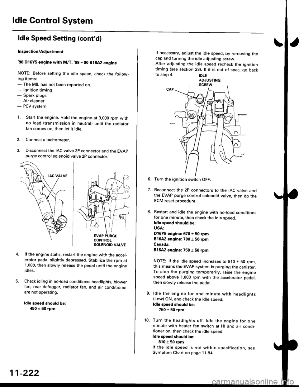
Disconnect the IAC valve 2P connector and the EVAPpurge controlsolenoid valve 2P connector.
EVAP PURGECONTROLSOLENOID VALVE
lf the engine stalls, restart the engine with the accel-erator pedal slightly depressed. Stabilize the rpm at1.000, then slowly release the pedal until the engineidles.
Check idling in no-load conditions: headlights, blowerfan, rear defogger, radiator fan, and air conditionerare not operating.
ldl€ speed should be:
450 i 50 rpm
11-222
lf necessary, adjust the idle speed, by removrng lnecap and turning the idle adjusting screw.After adjusting the idle speed recheck the ignitlontiming (see section 23). lf it is out of spec, go backto step 4. |DLE
6. Turn the ignition switch OFF.
7. Reconnect the 2P connectors to the IAC valve andthe EVAP purge control solenoid valve, then do theECM reset procedure.
8. Restart and idle the engine with no-load conditionsfor one minute, then check the idle sDeed.ldle speed should bo:
USA:
D16Y5 engine: 670 i 50 rpm
81642 engine: 700 i 50 rpm
Canada:
81642 engine: 750 t 50 rpm
NOTE: lf the idle speed increases to 8lO t 50 rpm,this means the EVAP system is purging the canister.To stop the purging temporarily, raise the enginespeed above 1,000 rpm with the accelerator pedal,
then slowly release the pedal.
9. ldle the engine for one minute with headlights(Low) ON. and check the idle speed.
ldle speed should be:
750 i 50 rpm
10. Turn the headlights off. ldle the engine for oneminute with heater fan switch at Hl and air condi-tioner on, then check the idle soeed.ldls speed should be:
810 t 50 rpm
lf the idle speed is not within specification, seeSymptom Chart on page 11-84.
Page 492 of 2189

\
I
'98 - 0O D16Y5 ongine with CvT
Adjust the idle speed using a Honda PGM Tester if pos-
sible. lf not, use the following procedure:
NOTE:
. Leave the IAC valve connected.
. Before s€tting the idle speed, check the following
rtems:- The MIL has not been reported on.
- lgnition timing
- Spark Plugs- Air clean€r
- PCV svstem
'1. Connect a tachometer.
2. Stan the engine. Hold the engine at 3,000 rpm w'th
no load (transmission in E or E] position) until the
radiator Jan comes on, then let it idle.
3. Check the idle speed under no-load conditions:
head lights, blower fan, rear defogger, radiator fan,
and air conditioner are not operatlng.
ldlo spaod ehould bo: 700 t 50 rpm
. lf the idle speed is within the specification, the
procedure is comPlete.
. lf the idle sDeed is out of specitication, 9o to step 4'
4. tf the idle speed is 810 1 50 rpm, this means the
EVAP system is purging the canister. To stop the
purging temporarily, raise the engine speed above
l,OO0 rgm with the accelsrator pedal. Slowly release
the pedal. and rscheck the idl€ speed.
. tf the idle speed is within the specificstion, the
Drocedure is comPlete.
. lf the idle sp€ed is out of spocification, go to step 5.
5. Disconnect th€ EVAP purgs control solenoid valve
2P connector.
EVAP PURGECONTROL
6. Remove the cap and turn the idle adiusting screw
1/2-turn clockwise or counterclockwlse
IDLE
7.After turning the idle adjusting screw 1/2-turn, check
the idl€ speed again. lf it is out of spec, turn the idle
adjusting screw 1/2-turn again.
NOTE: Do not turn the idle adjusting screw more
than 1/2-turn without checking the idle speed.
Turn the ignition switch OFF. Reconnect the EVAP
purge control solenoid valve 2P connector' then do
the ECM reset Procedure.
Start the engine. ldle the engine for one minute with
heater fan switch at Hl and air conditioner on, then
check the idle speed.
ldle spaed should be:
810 t 50 rpm (in El or E Posiiion)
lf the idle speed is not within specification, see
Svmptom Chart on Page 11-84.
9.
SOLENOID VALVE
11-223
Page 507 of 2189
Fuel Supply System
PGM-FI Main Relay (cont'dl
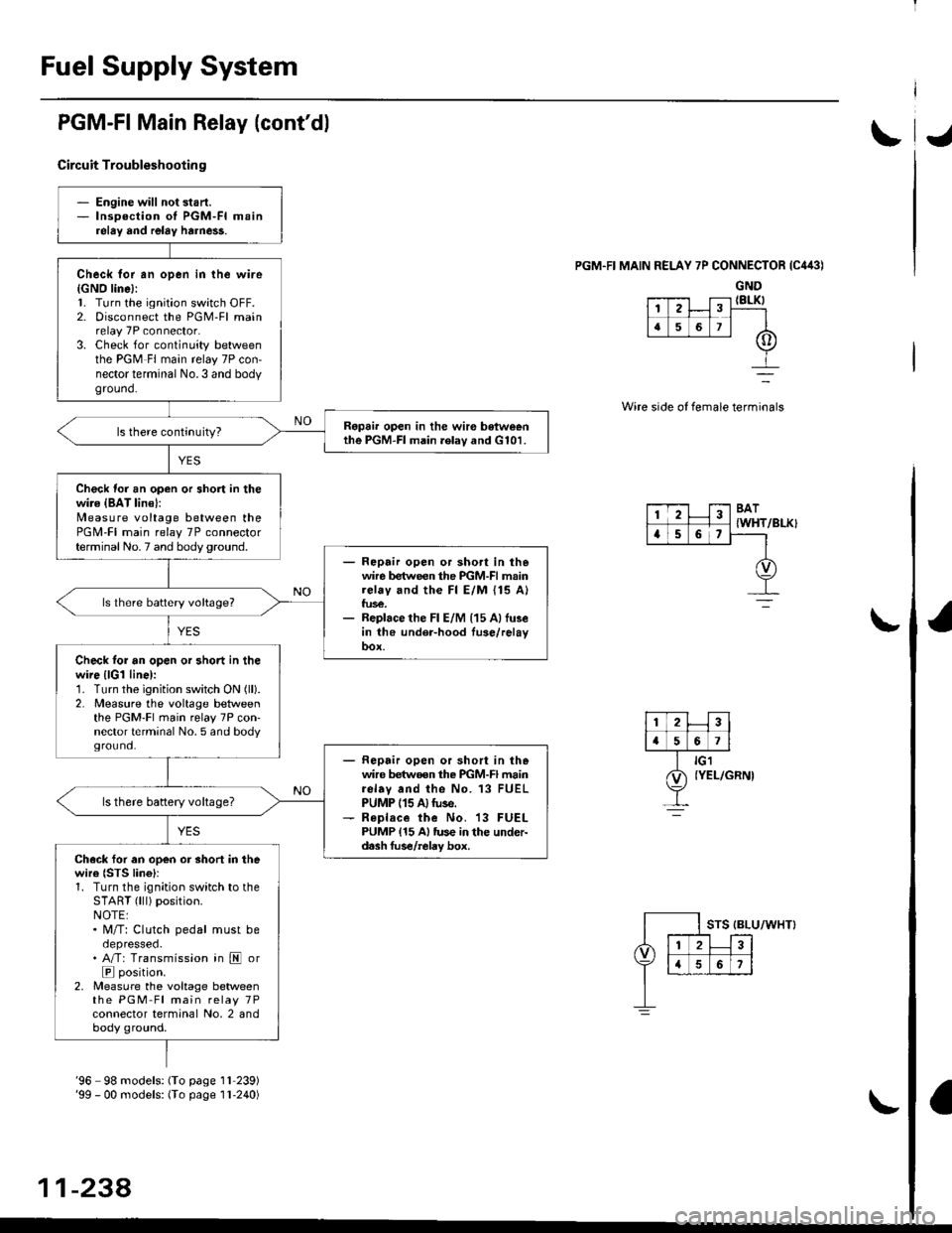
Circuit Troubleshootin g
PGM.FI MAIN RELAY 7P CONNECTOR {C443)
GND{8LK)
Wire side of female terminals
/BLK}
- Engine will not start.- lnsoection of PGM-FI mainrelay and relay harne$.
Check for an open in the wire{GNO line}:l. Turn the ignition switch OFF.2. Disconnect the PGM-Fl mainrelay 7P connector.3. Check for continuity betweenthe PGM Fl main relay 7P con-nector terminal No.3 and bodyground.
Ropai. open in the wir€ betweenthe PGM-FI main .elav and G101.
Check for an open or short in thewire {BAT lin€}:N4easure voltage between thePGM-FI main relay 7P connectorterminal No. 7 and body ground.- Repair open or sho.t in thewire between the PGM-FI mainrelay and the Fl E/M {15 A}fus€.- Replace the Fl E/M (15 Allu3ein the under-hood fuse/relayoox.
ls lhere battery voltage?
Check tor an open or short in thewire {lGl line):1. Turn the ignition switch ON (ll).
2. Measure the voltage betweenthe PGM-Fl main relay 7P con'nector terminal No. 5 and bodyground.- Repair open or short in thewire betwoen the PGM-FI mainrelav and the No. 13 FUELPUMP (15 A)tuse.- R€place the No. 13 FUELPUMP {15 A} tus€ in the under-d.sh fus€/relay box.
ls there battery voltage?
Ch.ck for an open or short in thewire {STS lino}r1. Turn the ignition switch to theSTART (lll) position.NOTE:. M/T: Clutch pedal must beoepresseo.. A/T: Transmission in E or
E position.2, Measure the voltage betweenthe PGM-Fl main relay 7Pconnector terminal No, 2 andbody ground.
12
[,a567
123BAT
{WHTa56,
'96 98 models: (To page 1l 239)'99 - 00 models: (To page I l-240)
11-238,
Page 514 of 2189
\J
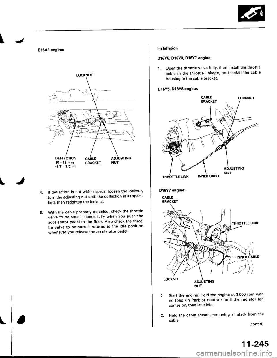
816A2 engine:
DEFLECTION10-12mmBla- 112inl
CABLE ADJUSTINGBRACKET NUT
t
lf deflection is not within specs' loosen the locknut'
turn the adjusting nut untilthe deflection is as speci-
fied, then retighten the locknut.
With the cable properly adiusted, check the thronle
valve to be sure it opens fully when you push the
accelerator pedal to the floor. Also check the throt-
tle valve to be sure it returns to the idle position
whenever you release the accelerator pedal'
LOCKNUT
lnstallation
Dl6Y5, Dr6Y8, D16Y, €ngine:
1. Open the throttle valve fully, then install the throttle
cable in the throttle linkage, and install the cable
housing in the cable bracket.
D16Y5, D16Y8 engins:
LOCKNUT
Start the engine. Hold the engine at 3,000 rpm with
no load (in Park or neutral) until the radiator fan
comes on, then let it idle.
Hold the cable sheath. removing all slack from the
caDle (cont'dl
11-245
Page 521 of 2189
Emission Gontrol System
System Description
The emission control system includes a Three Way Cata-lytic Convener (TWC), Exhaust Gas Recirculation (EGR)
system,. Positive Crankcase Ventilation (pCV) system andEvaporative Emission (EVAP) Control system. The emis-sion control system is designed to meet federal and stateemission standards.*: D16Y5 engine
Tailpipe Emission
Inspestion
@@ Do not smoke during ihis procedure. Keepany open flame away from your work area.
1. Start the engine. Hold the engine at 3,000 rpm withno load (in Park or neutral) until the radiator fancomes on. then let it idle.
2. Connect a tachometer.
Check and, if necessary, adjust the idle speed (see
page 11-220 - 223).
Warm up and calibrate the CO meter according to themeter manufacturer's instructions.
Check idle CO with the headlights, heater blower,rear window defogger, cooling fan, and air condition-er off.
NOTE: (Canada) Pull the parking brake lever up.Start the engine, then check that the headlights areoff.
CO mete. should indicate 0.1% maximum.
NOTE: '98 Dl6Y5 engine - lf the idle speed incress-es to 8101 50 rpm, this means the EVAp system ispurging the canister. To stop the purging temporari-ly. raise the engine speed above 1,000 rpm with theaccelerator pedal, then slowly release the pedal.
11-252
eFORWARD -
Three Way Catalytic Converter
(TWCI
Doscription
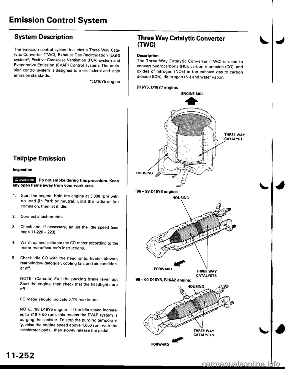
The Three Way Catalytic Converter (TWC) is used toconven hydrocarbons (HC), carbon monoxide (CO), andoxides of nitrogen (NOx) in the exhaust gas to carbondioxide (COr), dinitrogen (N,) and water vapor.
D15Y5, D16
, engine:
'99 - 00 D16Y8, 81642 engine:
ENGINE SIDE
t
Page 568 of 2189

J
t
Clutch
Speciaf Tools .......... ...........12-2
f lfustrated Index .......... ......12-3
clutch Pedal
Adjustment .................... 12'4
Clutch Master Cylinder
Removal/lnstallation ..... 12-5
Slave Cylinder
Removal/lnstallation .....12'6
Pressure Plate
Removal/lnspection ...... 12-7
Clutch Disc
Removal/lnspection ...... 12-8
Flywheel
Inspection ....................... 12-9
Replacement ....................................... 12-9
Clutch Disc, Pressure Plate
lnstallation ..................... 12-10
Release Bearing
Removal/lnspection ......12-11
f nstalfation .................,... 12-12
\
Page 571 of 2189
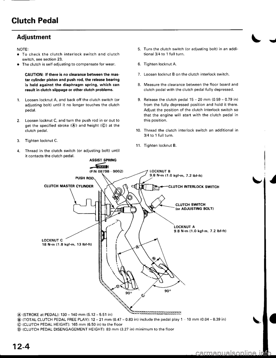
Glutch Pedal
Adjustment
NOTE:
. To check the clutch interlock switch and clutch
switch, see section 23.
. The clutch is self-adjusting to compensate for wear.
CAUTION: lf there is no clearance between the mas-
ter cylinder pislon and push rod, the release bearing
is held against the diaphragm spring, which can
result in clutch slippage 01 other clutch problems.
1. Loosen locknut A, and back off the clutch switch (or
adjusting bolt) until it no longer touches the clutch
peoar.
2. Loosen locknut C, and turn the push rod in or out to
get the specified stroke {@} and height (@) at tne
clutch pedal.
3. Tighten locknut C.
4. Thread in the clutch switch {or adiusting bolt) until
it contacts the clutch pedal.
9002)
Turn the clutch switch (or adjusting bolt) in an addi-
tional 3/4 to 1 full turn.
Tighten locknut A.
Loosen locknut B on the clutch interlock switch.
Measure the clearance between the floor board and
clutch pedal with the clutch pedal fully depressed.
Release the clutch pedal 15 - 20 mm {0.59 - 0.79 in)
from the fully depressed position and hold it there.
Adjust the position of the clutch interlock switch so
that the engine will start with the clutch pedal in
this position.
Thread the clutch interlock switch an additional in
3/4 to 1 full turn.
Tighten locknut B.
LOCKNUT B9.8 N.m (1.0 k91.m,7.2 lbt.tt)
INTERLOCK SWITCI{
J
'lL
5.
7.
8.
9.
10.
ASSIST SPRING
-Atl
CLUTCH SWITCH
lo. ADJUSTING BOLTI
LOCKNUT A9.8 N'm (1.0 kgI.m, 7.2 lbf,ft)
LOCKNUT C18 N.m {1.8 kql.m, 13lbf.ft}
@ (STROKE at PEDAL): 130 - 140 mm (5.12 - 5.51 in)
@ (TOTAL CLUTCH PEDAL FREE PTAYI: 12 - 21 mm (0.47 - 0.83 in) includethepedal play 1 10 mm (0.04 - 0.39 in)
@ (CLUTCH PEDAL HEIGHT): '�]65 mm {6.50 in) to the floor
@ (CLUTCH PEDAL DISENGAGEMENT HEIGHT): 83 mm (3.27 in) minimum to the floor
12-4
Page 572 of 2189
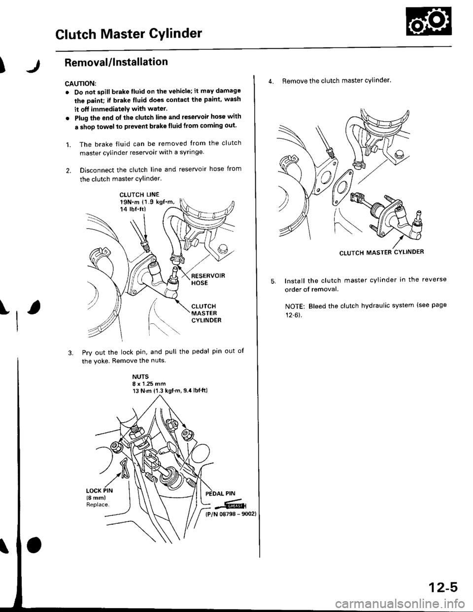
Glutch Master Gylinder
IRemovaUlnstallation
CAU'NON:
. Do not sDill brake lluid onthevehicle;it may damage
the paint; if brake fluid does contact the paint, wash
it off immediatelY with water.
. Plug the end ofthe clutch line and reservoir hos€ with
a shop towelto prevent brake tluid from coming out
1. The brake tluid can be removed from the clutch
master cylinder reservoir with a syringe
2. Disconnect the clutch line and reservoir hose from
the clutch master cylinder.
19N.m 11.9 kgf.m,14 tbf.ttl
[.
3. Pry out the lock pin, and pull the pedal pin out
the yoke. Remove the nuts
NUTS8 x 1 .25 mm13 N.m {'1.3 kgt.m,9.4lbf ft)
)
of
CLUTCH LINE
iffi,
4. Remove the clutch master cylinder.
CLUTCH MASTER CYLINDER
lnstall the clutch master cylinder in the reverse
order of removal.
NOTE: Bleed the clutch hydraulic system {see page
12-61,
12-5