1998 HONDA CIVIC Crank no start
[x] Cancel search: Crank no startPage 1088 of 2189
Inspection and Adjustment
Pump Belt
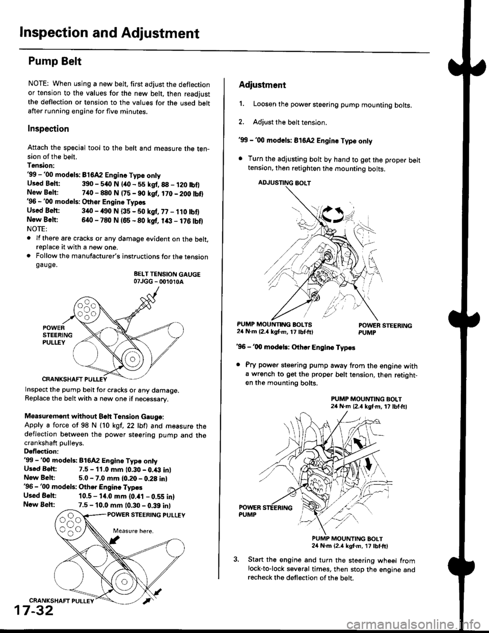
NOTE: When using a new belt, first adjust the deflection
or tension to the values for the new belt, then readjust
the deflection or tension to the values for the used beltafter running engine for five minutes.
Inspection
Attach the special tool to the belt and measure the ten-sion of the belt.
Tension:'99 -'00 mod€ls: B1642 Engin. Type onlyUsed Bsh: 390 - 540 N lao - 55 kgt.88 - 120 tbf)New Belt:740 - 880 N {75 - 90 kgf, 170 - 200 tbt}'96 - '00 models: Other Engine Types
Used Beh: 340 - 490 N (35 - 50 kgf, 77 - ilO tbflNew Belt:640 - 780 N 165 - 80 ksf, 1& - 176 tbf)NOTE:
. lf there are cracks or any damage evident on the belt,reDlace it with a new one.. Follow the manufacturer's instructions for the tensiongauge.
BELT TENSION GAUGE07JGG _ 001010A
Inspect the pump belt for cracks or any damage.Replace the belt with a new one if necessary.
Measuremont without Beh Tension Gauga:
Apply a force of 98 N (10 kgt,22 lbfl and measure thedeflection between the power steering pump and thecrankshaft pulleys.
Dsflectior:'99 -'00 model3: 816A2 Engine Typ€ ontyUsed Beh: 7.5 - 11.0 mm t0.30 - 0.43 inlNew Beh:5.0 - 7.0 mm (0.20 - 0.28 in)'96 - '00 models: Othor Engine Typos
Used Behi 10.5 - 14.0 mm (0.ial - 0.59 inlNow Beh:7.5 - 10.0 mm (0.30 - 0.39 inl
POWER STEERING PULUY
CRANKSHAFT PULLEY
17-32
Adiustment
1. Loosen the power steering pump mounting bolts.
2. Adjust the belt tension.
'99 - '00 mod€ls: 816A2 Engin€ Typo only
. Turn the adjusting bolt by hand to get the proper belttension, then retighten the mounting bolts,
ADJUSNNG BOLT
PUMP MOUNNNG BOLTS24 N.m (2.4 kgf'm, 17 tbtftlPOWER STEERINGPUMP
'96 -'00 modek: Othcr Engins Typos
. Pry power steering pump away from the engine witha wrench to get the proper belt tension, then retight-en the mounting bolts.
PUMP MOUNTING BOLT24 N.m (2,4 kgf.m, 17 lbl.ftl
PUMP MOUNTING BOLT24 N.m {2.a kgt m, 17 tbtftl
Start the engine and turn the steering wheel fromlock-to-lock several times, then stop the engine andrecheck the deflection of the belt,
Page 1486 of 2189

Connector ldentification and Wire Harness Routing
Engine Wire Harness lD16Y5, D16Y8 enginss): '96 - 98 models
Connector or
Torminal
Numbsr of
CavitissLocationConnects toNot€s
c 101c102c103c104c104c105c106c107c108c 109c110c111c112c113c114c115c116cl17c118c119c120cl21
c122c123cl23c124
c125
c127c12Ac129c130c131c132c 133c134c135
c136
c138c139c140c 141c142c 143c144cl44c145c'146cl47
10
1
22
14l4322l0I
2
2
2
2120
3l
14
14
1222
2
2
22
Left side of engine compartmentMiddle of engineMiddle of engineLeft side of engine companmentLeft side of engine compartmentMiddle of engineMiddle of engineMiddle of engineMiddle of engineMiddle of enginefvliddle of engineMiddle of engineMiddle of engineMiddle of engineMiddle of engineMiddle of engineMiddle of engineLeft side of engine compartmentMiddle of engineMiddle of engineMiddle of engineMiddle of engine
Middle of engineMiddle of engineMiddle of engineMiddle of engineMiddle of engineMiddle of engineMiddle of engineMiddle of engineMiddle of engineRight side of engine companmentBehind right kick panelUnder right side of dashUnder riOht side of dashUnder right side of dashUnder right side of dashUnder right side of dashUnder right side of dash
Under right side of dash
Under right side of dash
Middle of engineMiddle ot enginel iddle of engineMiddle of engineMiddle of ongineMiddle of engineLeft side of engine compartmentMiddle of engineMiddle of engineRight side of engine compartmentRight side of engine compartmentRight side of engine compartment
USACanada
Afi
USA
-' (A/r)
Main wire harness (C303)Crankshaft speed fluctuation (CKF) sensorEngine oil pressure switchAlternatorAlternatorNo. 'l fuel injectorNo. 2 fuel injectorNo.3 fuel injectorNo. 4 fuel injectorIAC valveThrottle position (TP) sensorl\4anifold absolute pressure (MAP) sensorIntake air temperature (lAT) sensorPower steering pressure {PSPI switchEVAP purge control solenoid valveJunction connectorJunction conn€ctorVehicle speed sensor {VSS}Countershaft speed sensorEngine coolant temp€rature (ECT) switch ADistributorEngine coolant temperature (ECT) sendingunrtEngine coolant temperature (ECT) sensorPrimary HO2S (sensor'l)Primary HO2S (sensor 1)Back-up light switchLock-up control solenoid valveSecondary HO2S (sensor 2)Mainshaft speed sensorLinear solgnoid valveShift control solsnoid valveStarter solenoidJunction connectorMain wire harnesE (C446)ECM/PCMPCMECMiPCMECM/PCMMain wire harness (C305)
Main wire harness (C305)
Main wire harness (C305)
Knock sensor (KS)IAC valveVTEC solenoid valveVTEC pressure switchEVAP control canister vent shut valveEGR control solenoid valveSecondary gear shaft speed sensorEGR valveEGR valveDrive pulley speed sensorSolenoid connector {CVT)Driven pulley speed sensor
*, (M/T)M/T*" INT\
*, tAtf)
NT:'96 model*,(A,/T):'97 - 98mooets
moqets
M/T
-1 (l,/T)*, (A,/T)-,(4,/T)*1 {M/T)*, (A,/T)*1 (CW)*, (A,T)
T101r102Left side of engine companmentRight side of engine companmentAlternatorUnder-hood fuse/relay boxG 101Middle of engineEngine ground, via engine wire harness
2
*1: Dl6Y5 engine*2: D16Y8 engine*3: D16Y5 (Ay'T), D16Y8 engines
3-16
Page 1488 of 2189
Gonnector ldentification and Wire Harness Routing
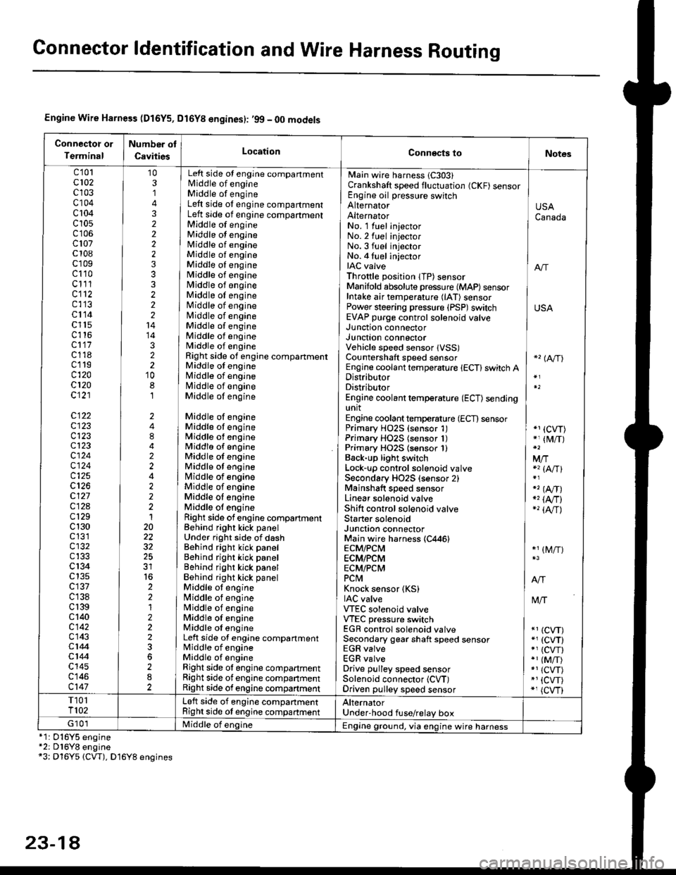
Engine Wire Harness (D16Y5, Dl6Yg engines): ,99 - 00 models
Connectot or
Terminal
Number ot
CavitiesLocationConn€cts toNotes
c'101cl02c103c104c 104c10s
c107c 108c'r09c110c111cl12c113cl14c l15c116cl17c118c119c120cl20c121
c122c123c123cl23cl24c124c125
c127c12Ac129c 130c131cl32c133c 134c135c137c138c 139c 140c142c143c144cl44c145c146c147
103,]
322223332221414322'10
8,l
2484224222120
32
2212223
282
No. 1 luel injector INo.2 fuel injectorNo.3 fuel injector ]No. 4 fuel injector iIAC valve I anThrottle position lTP) sensorManifold absolute pressure {MAP) sensor IIntake air temperature (lAT) sensor IPower steering pressure (PSP)switch USAEVAP purge control solenoid valve ]
Main wire harness 1C303)Crankshaft speed fluctuation (CKF) sensorEngine oil pressure switchAlternatorAlternator
Left side ot engine compartmentlvliddle of engineMiddle of engineLeft side ot engine compartmentLeft side of engine compartmentMiddle of engineMiddle ot engineMiddle of engineMiddle of engineMiddle oI engineMiddle of engineMiddle of engineMiddle of engineMiddle of engineNliddle of engineMiddle of engineMiddle of engineMiddle of engineRight side of engine compartmentMiddle of engineMiddle of engineN4iddle of engineMiddle of engine
Middle of engineMiddle ot engineMiddle ot engineMiddlo of engineMiddle of engineMiddle ot enginelrliddle of engineMiddle of engineMiddle oI engineMiddle ot engineRight side of engine compartmenlBehind right kick panelUnder right side of dashBehind right kick panelBehind right kick panelBehind righr kick panelBehind right kick panelMiddle ot engine[,liddle of engineN4iddle of engineMiddle of engineMiddle oI engineLeft side of engine compartmentMiddle of engineMiddle of engineRight side ol engine compartmentRight side of engine companmentRight side of engine compartment
USACanada
Junction connectorJUnct|On COnnectorVehicle speed sensor lVSS)Countershaft speed sensorEngine coolant temperature {ECT} switch ADistributorDistributorEngine coolant temperature (ECT) sendingunitEngine coolant temperature (ECT) sensorPrimary H02S (sensor 1)Primary HO2S (sensor 1)Primary HO2S lsensor 1)Back-up light switchLock'!p control solenoid valveSecondary HO2S (sensor 2)Mainshaft speed sensorLinear solenoid valveShift control solenoid valveStarter solenoidJunction connectorMain wire harness (C446)ECM/PCMECM/PCMECM/PCMPCtvtKnock sensor (KS)IAC valveVTEC solenoid valveVTEC pressure switchEGR control solenoid valveSecondary gear shaft speed sensorEGR valveEGR valveDrive pulley speed sensorSolenoid connector (CVT)Driven pulley speed sensor
*'� (A/TI
*1 (CVT)*, (M/T)
Mfia (A/Tl
" (A,/T)., (4,/r)-'� {AlrJ
*1 (M/T)
tvliT
*1 (CVT)*, (cvT)*' (cw)*1 (MiT)*1 {CVT)*1 {CVT)*, (cvr)
T101T102Left side of engine companmentRight side ot engine companmentAlternatorUnder'hood fuse/relay boxG 101Middle of englne IEngine ground, via engine wire harness*1: 016Y5*2: D16Y8*3: Dl6Y5
engineengine(CW), D16Y8 engines
23-14
Page 1494 of 2189
Connector ldentification and WireHarness Routing
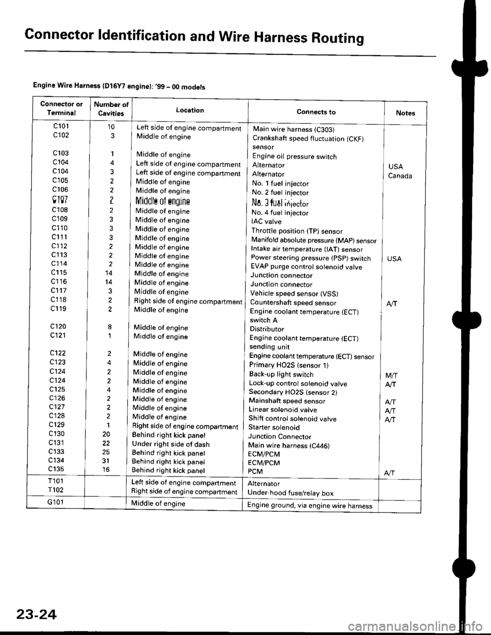
Engine Wire Harness (D15Y? engine): ,99 - OO models
c101
c102
cl03
c't04
c 104
c 105
cr 06
0107
c108
c109
c't 10
c11 r
c112
c113
c114
c115
c116
c117
cl18
c119
c120
c121
c122
c123
c124
c124
c125
c127
c128
c129
c 130
c 131
c134
c135
10
3
'I
3
?
2
3?
2
14
14
3
2
8
1
Left side of engine compartment
Middle of engine
fvliddle of engine
Left side of engine compartment
Left side of engine companment
Middle of engine
Middle of engine
Middlr ol sngins
Middle of engine
Middle of engine
Middle of engine
Middle of engine
Middle of engine
Middle of engine
Middle of engine
Middle of engine
Middle of engine
Middle of engine
Right side of engine compartment
Middle of engine
Middle of engine
Middle of engine
Middle of engine
Middle of engine
Middle of engine
Middle of engine
Middle of engine
Middle of engine
Middle of engine
Middle of engine
Right side ot engine compartment
Behind right kick panel
Under right side of dashBehind right kick panel
Behind right kick panel
Behind right kick panel
Main wire harness (C303)
Crankshaft speed fluctuation (CKF)
sensor
Engine oil pressure switch
Alternator
AlternatOr
No. l fuel injector
No.2 fuel injector
No. I fual itjecto,
No.4 fuel injector
IAC valve
Throttle position (TP) sensor
Manifold absolute pressure {MAp) sensorIntake air temperature 0AT) sensorPower steering pressure (PSp) switchEVAP purge control solenoid valveJunction connector
Junction connector
Vehicle speed sensor (VSS)
Countershaft speed sensor
Engine coolant temperature {ECT)switch A
Distributor
Engine coolant temperature (ECT)
sending unit
Engine coolant temperature (ECT) sensor
Primary HO2S (sensor 1)
Back-up light switch
Lock-up control solenoid valveSecondary HO2S (sensor 2)Mainshaft speed sensor
Linear solenoid valve
Shift control solenoid valve
Starter solenoid
Junction Connector
Main wire harness (C446)
ECM/PCM
ECM/PCM
PCM
USA
Canada
M/T
Atr
Atr
Alr
Al-|.
Left side of engine compartment
Right side of engine compartment
Middle of engineEngine ground, via engine wire harness
23-24
Page 1496 of 2189
Connector ldentification and WireHarness Routing
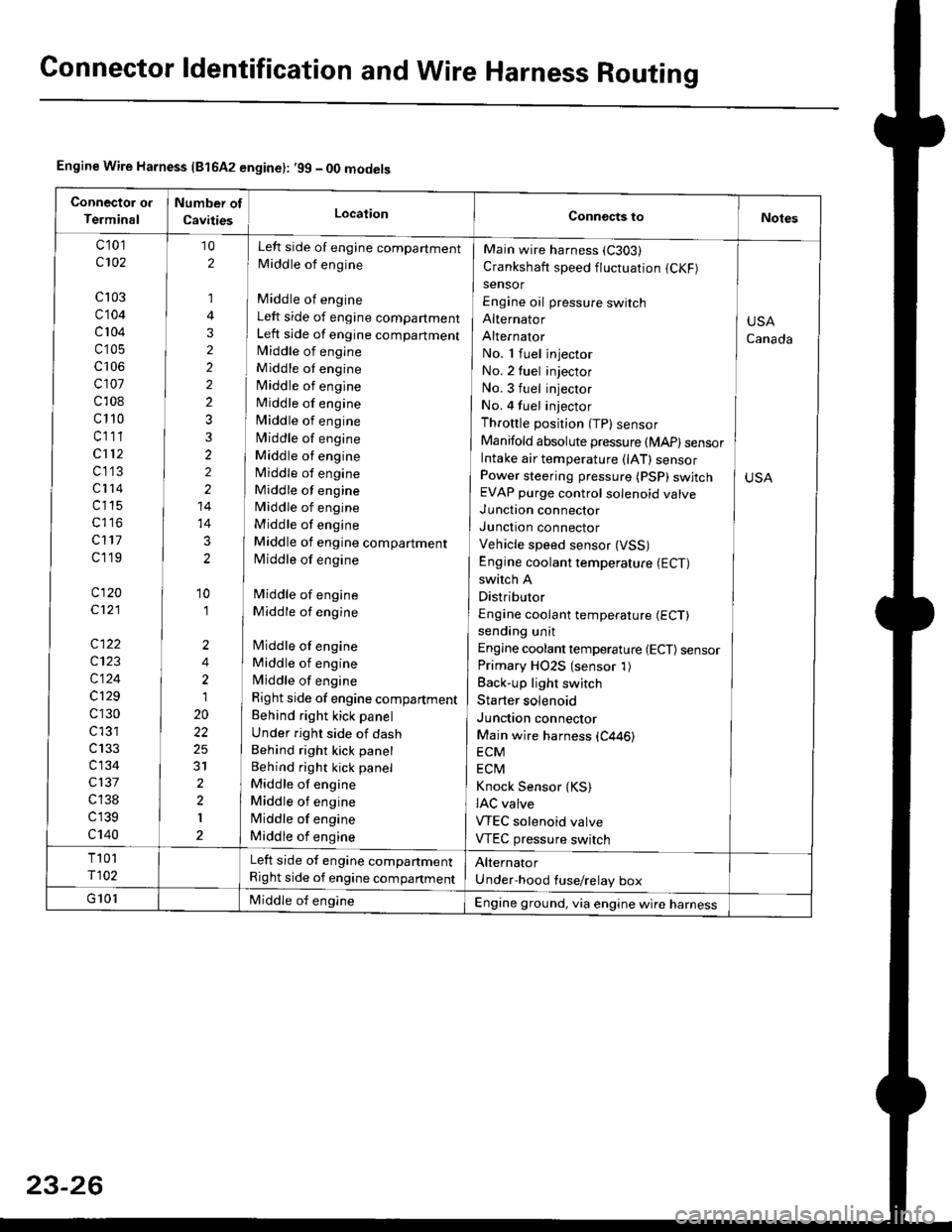
Engine Wire Harness {81642 engine}: .99 - 00 models
c 101
c102
cl03
c104
c 104
c'105
c106
cl01
c108
c110
cl11
cl12
c1'13
c114
c115
c117
cl19
c120
c121
c122
c123
c124
c129
c130
c l31
c133
c134
c137
c 138
c139
c140
Left side of engine companment
Middle of engine
Middle of engine
Left side of engine compartment
Left side of engine compartmentlvliddle of engine
Middle ot engine
Middle of engine
Middle of engine
Middle of engine
Middle of engine
Middle ot engine
Middle of engine
Middle of engine
Middle of engine
Middle of engine
Middle of engine compartment
Middle of engine
Middle of engine
Middle of engine
lMiddle of engine
Middle of engine
Middle of engine
Right side of engine compartment
Behind right kick panel
Under right side of dash
Behind right kick panel
Behind right kick panel
Middle of engine
Middle ot engine
lMiddle of engine
Middle of engine
10
2
,]
4
3
2
2
2
2
3
3
2
2
2
14
14
3
2
'10
'I
2
4
2
1
20
22
25
31
2
2
I
Main wire harness (C303)
Crankshaft speed fluctuation (CKF)
sensor
Engine oil pressure switch
Alternator
Alternator
No. 1 fuel injector
No. 2 tuel injector
No. 3 fuel injector
No. 4 fuel injector
Throttle position (TP) sensor
Manifold absolute pressure (MAP) sensorIntake air temperature (lAT) sensorPower steering pressure (PSP) swjtchEVAP purge control solenoid valve
Junction connector
Junction connector
Vehicle speed sensor (VSS)
Engine coolant temperature (ECT)
switch A
Distributor
Engine coolant temperature (ECT)
sending unit
Engine coolant temperature {ECT) sensorPrimary HO2S (sensor 1)
Back-up light switch
Starter solenoid
Junction connector
Main wire harness (C446)
ECM
ECtvl
Knock Sensor {KS)IAC valve
VTEC solenoid valve
VTEC pressure switch
USA
Canada
Left side of engine companment
Right side of engine compartment
Engine ground, via engine wire harness
Page 1565 of 2189
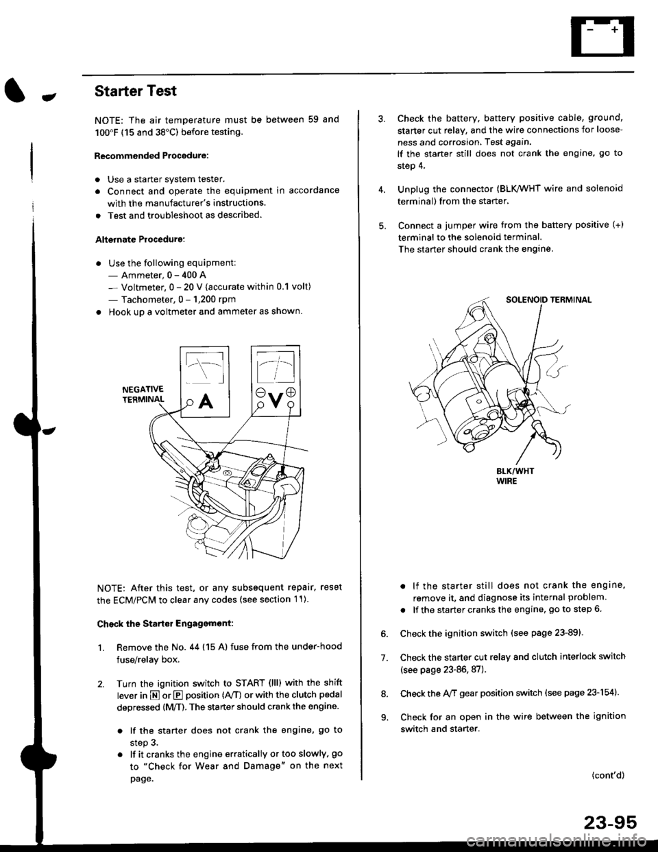
-Starter Test
NOTE; The air temoerature must be between 59 and
100'F (15 and 38"C) before testing.
Recommended Procedure:
. Use a staner system tester.
. Connect and operate the equipment in accordance
with the manufacturer's instructions.
. Test and troubleshoot as described,
Alternate Procedurg:
. Use the following equipment:- Ammeter, 0 - 400 A
- Voltmeter, 0 - 20 V (accurate within 0.1 volt)
- Tachometer, 0 - 1,200 rpm
. Hook up a voltmeter and ammeter as shown.
NEGATIVETERMINAL
NOTE: After this test, or any subsequent repair. reset
the ECM/PCM to clear any codes (see section l1)
Check the Start€r Engagemont:
1. Remove the No. 44 (15 A) fuse from the under-hood
fuse/relay box,
2. Turn the ignition switch to START (llll with the shift
lever in E or E position (rVT) or with the clutch pedal
depressed {M/T). The starter should crank the engine.
. lf the starter does not crank the engine, go to
step 3.
. lf itcranksthe engineerraticallyortooslowly, go
to "Check for Wear and Damage" on the next
page.
Check the battery. battery positive cable, ground,
starter cut relay, and the wire connections for loose-
ness and corrosion, Test again.
lf the starter still does not crank the engine, go to
step 4,
Unplug the connector (BLK,/WHT wire and solenoid
terminal) from the starter,
Connect a jumper wire from the battery positive (+)
terminal to the solenoid terminal.
The starter should crank the engine.
. lf the starter still does not crank the engine,
remove it, and diagnose its internal problem
. lf the startercranksthe engine, goto step 6.
Check the ignition switch (see page 23-891.
Check the starter cut relay and clutch interlock switch
(see page 23-86,87).
Check the A/f gear position switch (see page 23-154).
Check for an open in the wire between the ignition
switch and starter.
7.
(cont'd)
23-95
9.
Page 1566 of 2189
Starting System
Starter Test lcont'dl
Ch€ck tor Wear and Damage
The starter should crank the engine smoothly and
steadily, lf the starter engages. but cranks the engine
erratically, remove it, and inspect the starter drive gear
and torque converter or flywheel ring gear for damage.
. Check the drive gear overrunning clutch for binding
or slipping when the armature is rotated with the
drive gear held,- lf damaged. replace the gears.
Check Cranking Voltsge and Curr€nt Draw
Cranking voltage should be no less than 8.5 volts.
Current draw should be no more than 350 amperes.
lf cranking voltage is too low, or current draw too high,
check for;
. dead or low batterv.
. open circuit in starter armature commutator seg-
ments,
. starter armature dragging.
. shorted armature winding.
o excessive drag in engine.
Check Cranking rpm
Engine speed during cranking should be above 100 rpm,
lf speed is too low, check for:
. loose battery or stanerterminals.
. excessively worn starter brushes,
. open circuit in commutator segments.
o dirty or damaged helical spline or drive gear.
. defective drive gear overrunning clutch.
Check Siarter Disengag€ment
With the shift lever in El or @ position (A/T) or with the
clutch pedal depressed (M/T), turn the ignition switch to
START (lll), and release to ON (ll).
The starter drive gear should disengage from the torque
converter or flywheel ring gear when you release the
Key.
lf the drive gear hangs up on the torque converter or fly-
wheel ring gear, check for:
. solenoid plunger and switch malfunction,
. dirty drive gear assembly or damaged overrunning
clutch.
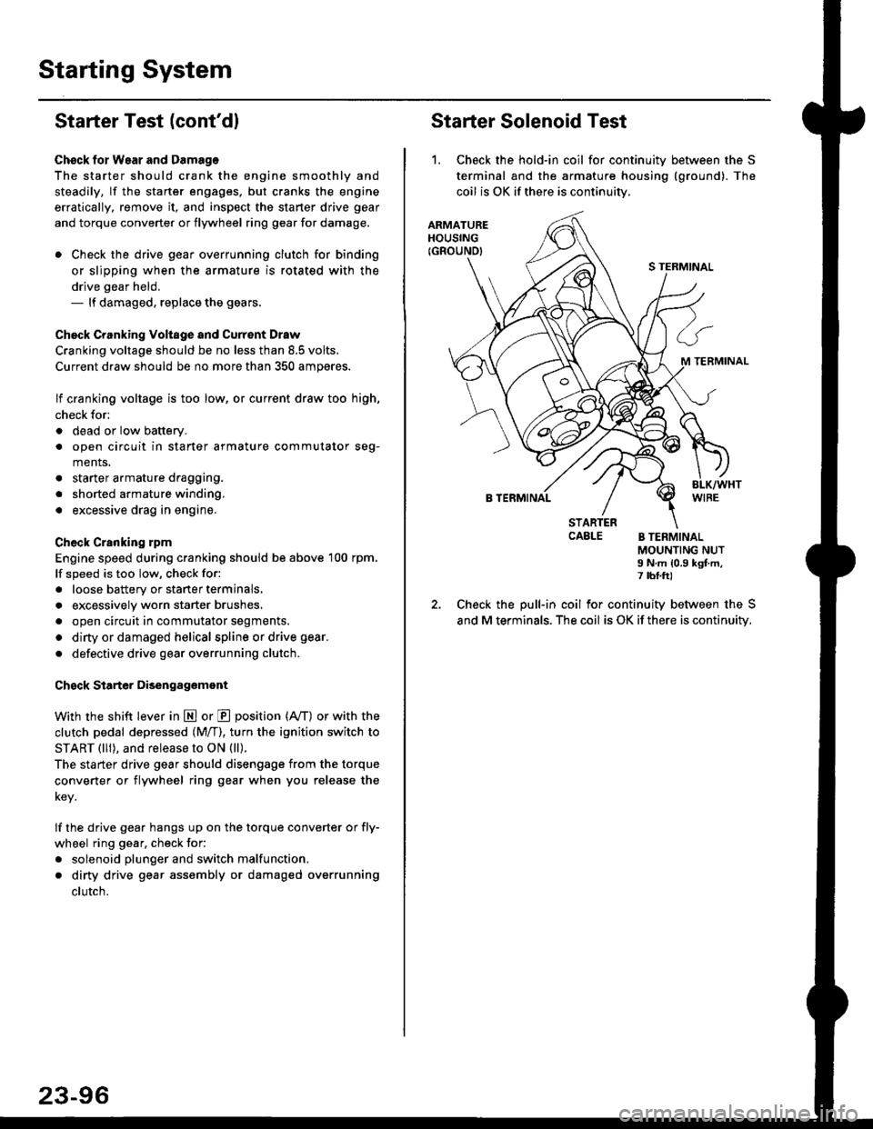
Starter Solenoid Test
1. Check the hold-in coil for continuitv between the S
terminal and the armature housing (ground). The
coil is OK if there is continuitv,
ARMATUREHOUSING(GROUND)
S TERMINAL
M TERMINAL
B TERMINAL
STARTERCAELE B TERMINALMOUNTING NUTI N.m {0.9 kgf.m,7 tbf.ft)
Check the pull-in coil for continuity between the S
and M terminals. The coil is OK if there is continuity.
Page 1969 of 2189
Brake System Indicator Light (cont'd)
- How the Circuit Works
The brake system indicator light comes on to alert
the driver that the parking brake is applied, or that
the brake fluid level is low. lt also comes on as a
bulb test when the engine is cranked.
Parking Brake
With the ignition switch in ON (ll) or START (lll),
voltage is applied through fuse 25 to the brake
system light. When you apply the parking brake, the
switch closes and provides a ground for the light.
The light then comes on to remind you that the
parking brake is applied.
Brake Fluid Level
With the ignition switch in ON (ll) or START (lll),
voltage is applied through fuse 25 to the brake
system light. lf the brake fluid level is low, the brake
fluid level switch closes, providing ground to the
circuit. The brake system light then comes on,
alerting the d verto a low brake fluid level in the
brake master cylinder. (Check brake pad wear
before you add fluid).
Bulb Check
With the ignition switch in START (lll) and clutch
pedal depressed or A'lT gear selector in PARK (P)
or NEUTRAL (N), voltage is applied through fuse 31
to the brake bulb check circuit. The brake bulb
check circuit closes, allowing current to flow through
the brake system light and bulb check circuit to
ground. The brake system light then comes on to
test the bulb.
Refer to the Service Manual (Section 23, Electrical)
for specific tests or troubleshooting procedures.
71-2
a
\fa