Page 733 of 2189
E i"dl.r." fiSh, 1."""". y{*fu
Reference page
14- 101
lE indicator light does not come on for two seconds after ignition switch is first turned oN (ll).14-102
Shift lever cannot be moved from E position with the brake pedal deprsssed'14-104
lf the self-diagnostic E indicator light does not blink and following symptoms appear, perform an inspection according to
the table below.
14-55
Page 757 of 2189
Troubleshooting Flowchart - Brake Switch Signal
Symptom
Shift lever cannol b€ moved f.om
B pGition with the brako podrl
depr8sed.
PCM CONNECTORS
Check Brako Light Operation:Deoress the brake pedal.
Rop.ir faulty braks switch cilcuit
lsos soction 231.Are the brake lights ON?
Measure SToP SW Vohag€:1. Turn the ignition switch OFF.2. Disconnect the A l32P) and D
{l6P) connectors from thoPCM.3. Measure the voltage belweenthe D5 and A9 or A22 termi-nals with the brake Pedaldepressod.
Rap.i. opon in the wira bctn oentha 05 terminal and tho btrkclwitdr.ls there battery voltage?
. Brake switch 3ign.l is OK.. Ch6ck lor looao PCM oonnoctors.It nocassary, aubctilute a known-good PCM and r€check.. Inspoct the brake switch circuit
{s6e section 231.
Wire side of lemale terminals
Page 782 of 2189
ElectricalTroubleshooting ('99 - 00 Modelsl
Troubleshooting Flowchart - Brake Switch Signal
PCM CONNECTORS
Wire side of female terminals
Shift lever cannot be moved tromE position with tho b.ake pedaldepressod.
Check Brake Light Operation:Depress the brake pedal.
Repair t ulty brake switch circuit{see s€ction 23}.Are the brake llghts ON?
Mea3ure STOP SW Vohage:1. Turn the ignition switch OFF.2. Disconnect the A (32P) and B{25P} connectors from thePCM,3. Measure the voltage betweenthe A32 and 820 or 822 termi-nals with the brake pedal
depressed.
Repair open in the wire betwsenthe A32 terminal rnd tho brrk6switch.
ls there battery voltage?
. Brak€ switch sign.l is OK.. Check for loose terminal fil inlhe PCM conn€ctors. lf neces-sary. substitute a known-goodPICM and recheck.. InsDect the breke 3witch circuitlsee section 231.
B {25P)
\
14-104
Page 791 of 2189

Road Test
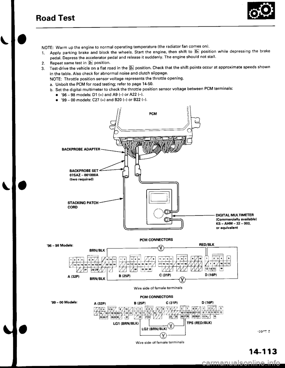
NOTE: Warm up the engine to normal operating tem peratu re (the rad iator fan comes on )'
1. Apply parking brake and block the wheels. Start the engine, then shift to E position while depressing the brake
Dedal, Depress the accelerator pedal and release it suddenly. The engine should not stall'
2. Repeat same test in E Position.
3. Test-drive the vehicle on a flat road in the E position. Check that the shift points occur at approximate speeds shown
in the table. Also check for abnormal noise and clutch slippage.
NOTE: Throttle position sensor voltage represents the throttle opening
a. Unbolt the PCM for road testing; refer to page 14-50.
b. Setthedigital multimeter to check the th rottle position sensor voltage between PCM terminals;
. '96 - 98 models: D1 {+) and A9 (-) or 422 (-}.
. '99 - 00 models: C27 (+) andB20t-) orB22{-}.
BACKPROBE ADAPTER
BACKPROBE SET07sAz - 001oq)A{two requiredl
DIGIIAL MULTIMETERlCommercially available)KS-AHM-32-003,or equivalenl
'96 - 98 Modelsr
Wire side ol temale terminals
PCM CONNECTORS
B t25Pl c (31P)
LG1 IBRN/BLK)
I (25P1c (31P}
A t32PtD (16P)
Wire side ol female terminals
'9!t - 00 Models:
1+113
Page 794 of 2189

Stall Speed
Test
CAUTION:
. To prev€nt transmission damage, do not t6st stall speed for more than ro sgconds at a time.. Do not shift the levor while raising the engine speed.. Bo sule lo remove the pressure gauge betoro testing stall speed.
'1. Engage the parking brake, and block the front wheels.
2. Connect a tachometer to the engine, and start the engine.
3. Make sure the Ay'C switch is OFF.
4. After the engine has warmed up to normal operating temperature (the radiator fan comes on). shift into E position.
5. Fully depress the brake pedal and accelerator for 6 to g seconds, and note engine speed.
6. Allow two minutes for cooling, then repeat the test in @ and @ positions.
NOTE:
. Stall speed tests should be used for diagnostic purposes only,. Stall speed should be the same in o., E and E positions.
Stall Spsed RPM:
Specification: 2.700 rpm
Service Limit: 2,550 - 2,850 rDm
TROUBLEPROBABLE CAUSE
. Low fluid level or ATF pump outDur. Clogged ATF strainer. Pressure regulator valve sluck closeo. Slipping clutch
. Slippage of 4th ctutch
. Slippage of 2nd clutch
. Slippage of lst clut"tr or. t"t g""io*-*"y "lut"h
Stall rpm high in D., E and E positions
Stall rpm high in El position
Stall rpm high in E posirion
Stall rpm high in E position
Stall rpm low in LDa . El and E positrons. Engine output low. Torque converter one-way clutch slipping
14-116
Page 906 of 2189

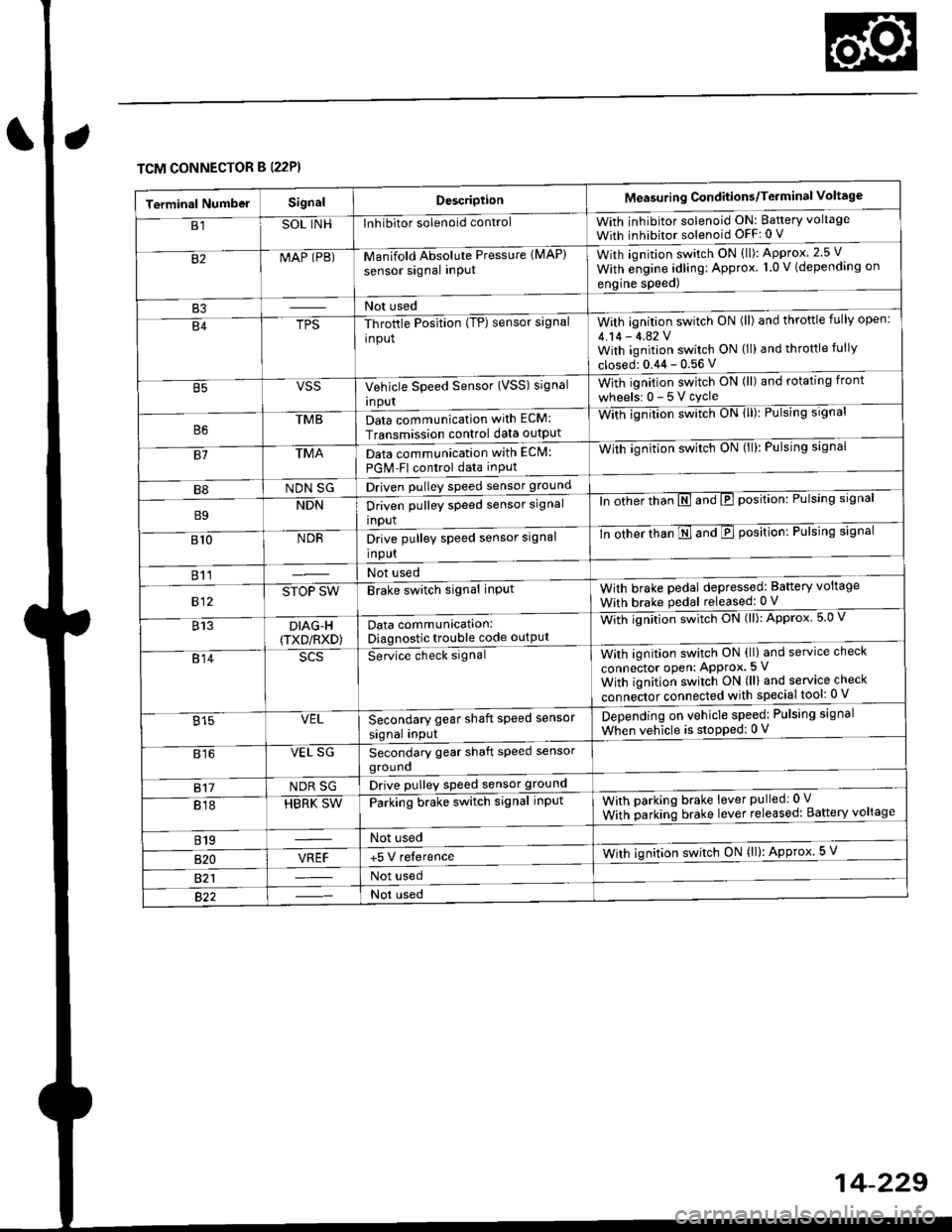
TCM CONNECTOR B (22P}
Terminal NumbelSignalDescriptionMeasuring Conditions/Terminal Voltage
B1SOL INHInhibitor solenoid controlWith inhibitor solenoid ON: Baftery voltage
With inhibitor solenoid OFF: 0 V
82MAP (PB)-M an if old Absol r-rte Pressure IMAP)
sensor signal inPUtWith iqnition switch ON (ll): Approx.2.5 V
With e;gine adling: Approx. 1.0 V (depending on
engine speed)
B3Not used
B4TPS-Throttle Position (TP) sensor signal
input
With ignition switch ON (ll) and throftle fully open:
4.14 - 4.42 VWith ignition switch ON (ll) and throttle fully
closed: 0.44 - 0.56 V
VSSVehicle Speed Sensor (VSS) signal
Inpur
With ignition switch ON (ll) and rotating front
wheelsr 0-5Vcycle
TMBData communication with ECM:
Transmission control data outpUt
With ignilion swltch UN lll): rulslng slgnar
81TMAData communication with EClvl:
PGM Fl control data inPut
With ignition swltch uN {ll,: l-ulslng slgnal
B8NDN SGDriven pulley speed sensor ground
B9NDNDriven pulley speed sensor signal
input
ln other thTnE and E position: Pulsing signal
810NDRDrive pulley speed sensor signal
Input
-tn ottrer ttran E ana E position: Pulsing signal
811Not used
812STOP SWBrake switch signal inPutWith brake pedal depressed: Battery voltage
With brake pedal released: 0 V
813DIAG-H(TXD/RXD)Data communication:Diagnostic trouble code outPut
Wittr ignitio.r s*itct' ON (ll): Approx 5.0 V
814Se-ice ctrect signatWith ignition switch ON (ll) and service check
connector oPen: APProx.5 V
With iqnition switch ON (ll) and service check
"onn"itot. connect"d with special tool: 0 V
Secondary gear shaft speed sensor
signal input
Depending on vehicle speed: Pulsing signal
When vehicle is stoPped: 0 V815VEL
816VEL SGSecondary gear shaft speed sensorgrouno
817NDR SGDrive pulley speed sensor ground
818HBRK SWParking brake switch signal inPutWith parking brake lever pulledr 0 V
With parking brake lever released: Battery voltage
819Not used
B�20VREF+5 V relerenceWith ignition switch ON (ll): Approx 5 V
821Not used
Not used
Page 909 of 2189

PGM Terminal Voltage/Measuring Conditions ('99 - 00 Modelsl
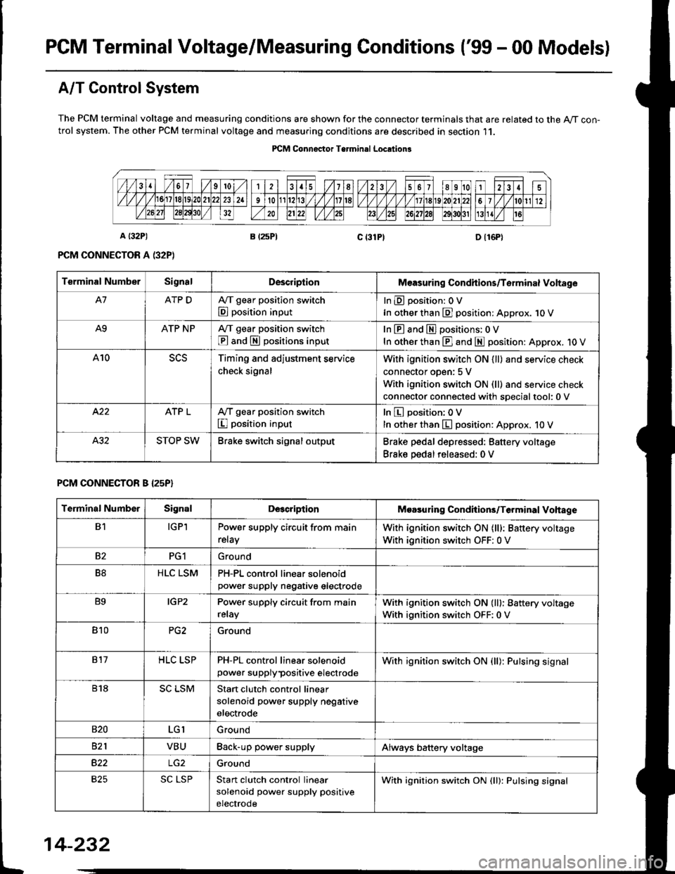
A/T Control System
The PCM terminal voltage and measuring conditions are shown for the connector terminals that are related to the A/T con-trol system. The other PCM terminal voltage and measuring conditions are described in section 11.
PICM Connoctor Terminrl Location3
Terminal NumberSignalDescriplionMeasuring Condhions/Torminal Voltage
A7ATP DA,/T gear position switch
E position input
InEposition:OV
In other than E] position: Approx. 1O V
A9ATP NPA/T gear position switch
@ and S positions input
In E and El positions: 0 V
In other than E] and E position: Approx. 1O V
A10Timing and adjustment service
check signal
With ignition switch ON {ll} and service check
connector oDen: 5 V
With ignition switch ON (ll) and service check
connector connected with soecialtool:0 v
ATP LA,/T gear position switch
I position input
In E position; OV
In other than E position: Approx. 10 V
STOP SWBrake switch signal outputBrake pedal depressed: Battery voltage
Brake pedal released: 0 V
PCM CONNECTOR B I25P}
Terminal NumberSignalDescriptionMoasuring Condhions/Terminal Vohage
B1IGPlPower supply circuit from main
relay
With ignition switch ON (lll: Battery voltage
With ignition switch OFF: 0 V
82PG1Ground
B8HLC LSMPH-PL control linear solenoidpower supply neqative electrode
B9IGP2Power supply circuit from main
relay
With ignition switch ON (lll: Battery voltage
With ignition switch OFF:0 V
810PG2Ground
817HLC LSPPH-PL control linear solenoid
power supplypositive electrode
With ignition switch ON {ll): Pulsing signal
818SC LSMStart clutch control linear
solenoid power supply negative
electrode
s20LGIGround
821VBUBack-up power supplyAlways battery voltage
B22Ground
825SC LSPStan clutch control linear
solenoid power supply positive
electrode
With ignition switch ON (ll): Pulsing signal
t
14-232
Page 970 of 2189

Start Clutch Control@
T
Start Clutch Calibration Procedure
NOTE: When the following parts are replaced, the TCM
must memorize the feedback signal for the start clutch
control.
. TCM
. Transmissionassembly
. Stan clutch assembly
. Lower valve bodv assembly
. Engine assembly or overhaul
'96 Model Only
CAUTION: Do not uso this procsdure on'97 - (X) mod-
els or you will damage the transmission. On '97 - 00
models, the TCM or PCM memorizes ths loodback sig'
nals when you drive the vehicle.
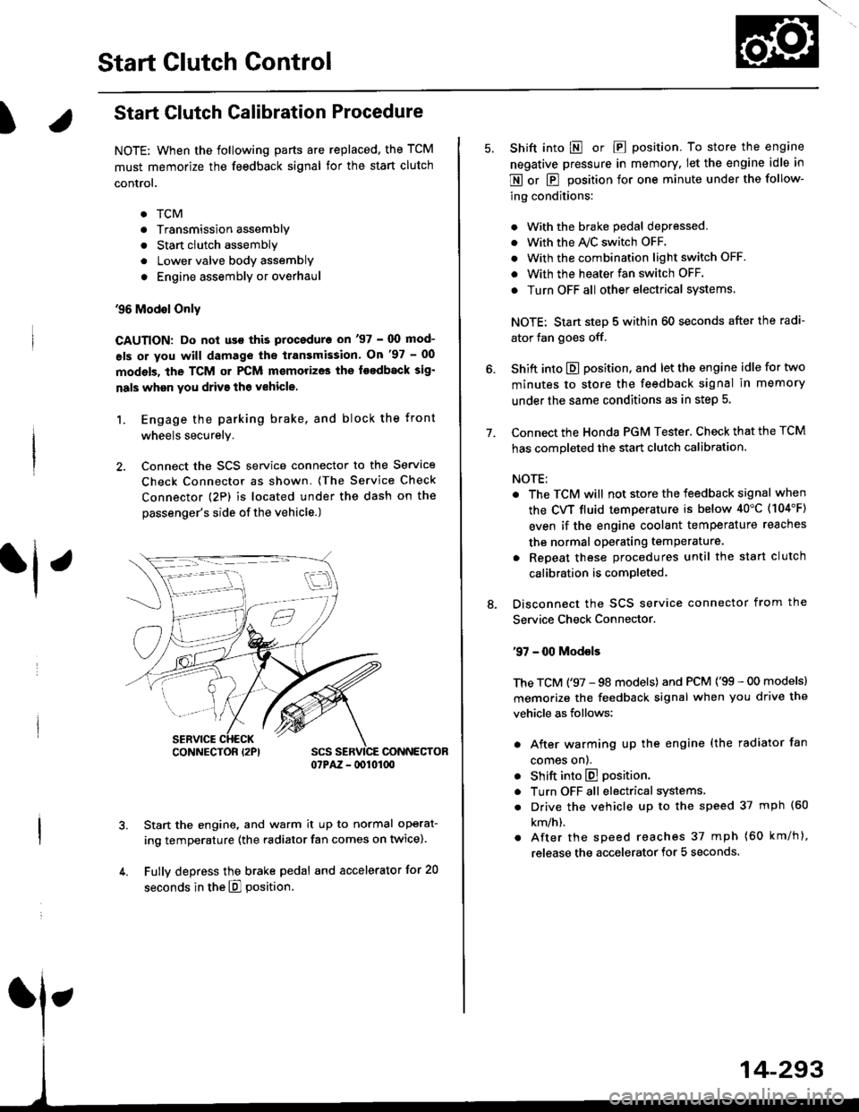
1. Engage the parking brake, and block the front
wheels securely.
2. Connect the SCS service connector to the Service
Check Connector as shown. (The Service Check
connector (2P) is located under the dash on the
passenger's side of the vehicle.)
CONNECTOR07PAZ - lDl01(xt
Start the engine, and warm it up to normal operat-
ing temperature (the radiator fan comes on twice).
Fully depress the brake pedal and accelerator for 20
seconds in the E] position.
rl ,
CONNECTOR I2PI
14-293
7.
Shift into E o|. E position. To store the engine
negative pressure in memory. Iet the engine idle in
E or E position for one minute under the follow-
ing conditions:
. With the brake pedal depressed,
. with the y'\/c switch oFF.
. With the combination light switch OFF.
. With the heater fan switch OFF.
. Turn OFF all other electrical systems
NOTE: Start step 5 within 60 seconds after the radi-
ator fan goes off.
Shift into E position, and let the engine idle for two
minutes to store the feedback signal in memory
under the same conditions as in step 5.
Connect the Honda PGM Tester. Check that the TCM
has completed the start clutch calibration.
NOTE:
. The TCM will not store the feedback signal when
the CVT fluid temperature is below 40"C (104'F)
even if the engine coolant temperature reaches
the normal operating temperature.
. Repeat these procedures until the start clutch
calibration is completed-
Disconnect the SCS service connector from the
Service Check Connector.
'97 - 00 Models
The TCM ('97 - 98 models) and PCM ('99 - 00 models)
memorize the feedback signal when you drive the
vehicle as follows:
. After warming up the engine (the radiator fan
comes onl.
. Shift into E position.
. Turn OFF all electrical systems,
. Drive the vehicle up to the speed 37 mph (60
km/h).
. After the speed reaches 37 mph (60 km/h),
release the accelerator for 5 seconds.