1998 HONDA CIVIC troubleshoot
[x] Cancel search: troubleshootPage 1796 of 2189
Troubleshooting
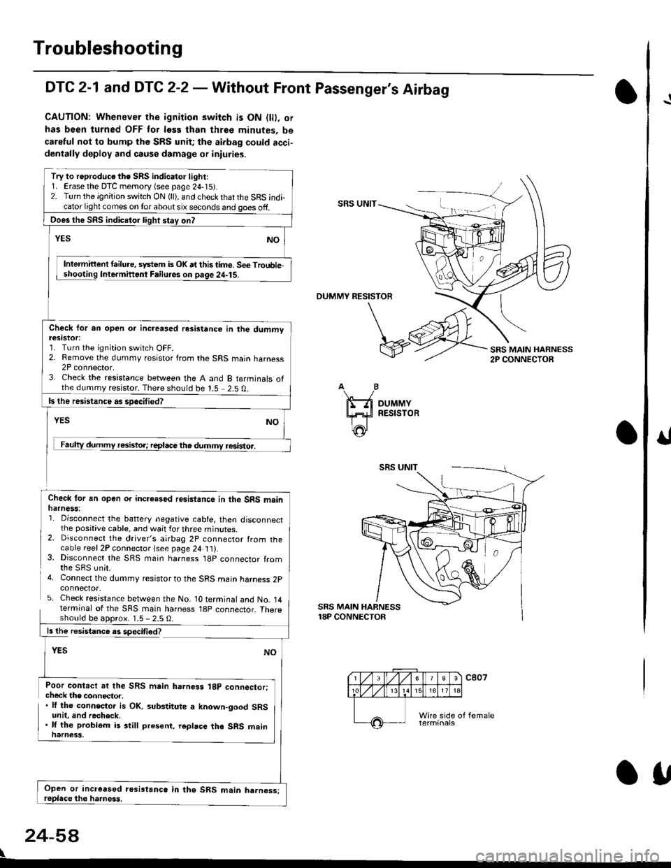
DTC 2-1 and DTC 2-2 - Wathout Front Passenger's Airbag
CAUTION: Whenever the ignition switch is ON {lll. or
has been turned OFF tor less than three minutes, be
caretul not to bump the SRS unit; the aidag could acci-dentally deploy and causs damage or iniuries.
Try to reproduc€ the SRS indicator light:1. Erase the DTC memory {see page 24-15r.2. Turn the ignition switch ON (ll), and check thatthe SRS indicator light comes on lor about six seconds and ooes off.SRS UNIT
Intermittent failu.e, system is OK at this time. Se€ Trouble-Intermifient Failuies on paqe 24-15.
OUMMY RESISTOR
Check for an open oa increased resistance in the dummvteslstot:1. Turn the ignition switch OFF.2. Remove the dummy resistor from the SRS main harness2P connector,3. Check the resistance between the A and B terminals ofthe dummy resistor. There should be 1.5 - 2.5 0.
resistoa.
Check lor an open or incre.sed resisiance in the SRS mainharness:'1. Disconnect the battery negative cable, then disconnectthe positive cable, and wait for three minutes.2. Disconnect the driver's airbag 2P connector from thecable reel2P connector lsee page 24 t t).3. Disconnect the SRS main harness t8p connector fromthe SBS unit.4. Connect the dummy resistor to the SRS main harness 2pconnector.5. Check resistance between the No- 1O terminal and No. 14terminal of the SRS main harness 18p connector. Thereshould be aDorox. 1.5 - 2.5 0.
SRS MAIN HARNESS18P CONNECTOR
ls the resistance es speciti€d?
YES
Poor contact ar the SRS main hahess 18p connector;check the connector.. lf the connector is OK. substitute a known-good SRSunit, and recheck.. lf the problem is still present. repbce the SRS mainnarness.
24-5A
\
Ooes the SRS indicalor light stay on?
Open or increased resi3tanc6 in tho SRS main harness;OU
I
Page 1798 of 2189
Troubleshooting
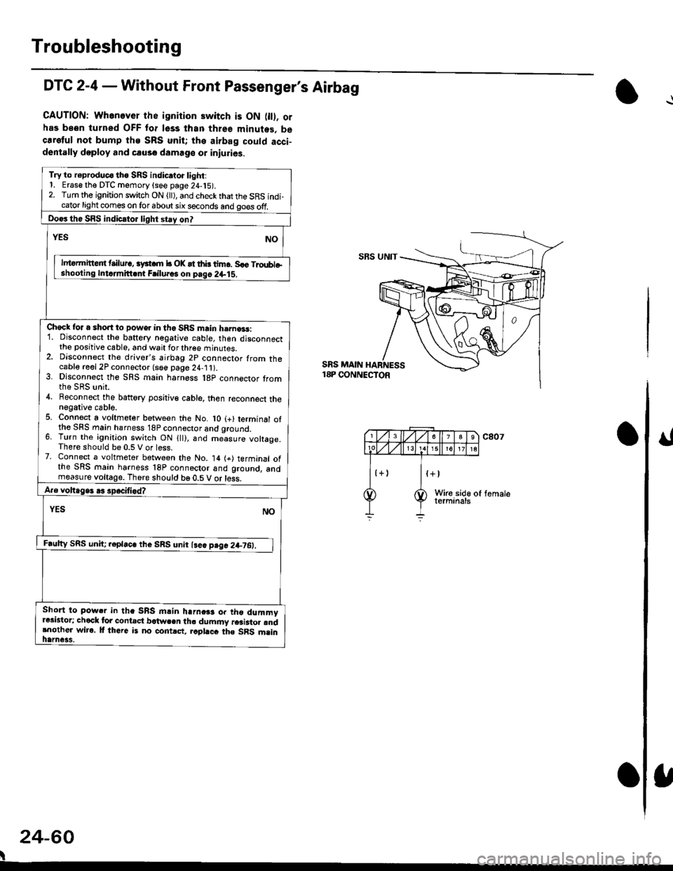
DTC 2-4 - Without Front Passenger's Airbag
CAUTION: Whenever the ignition switch is ON 0l). orhas been turned OFF for lsss lhan three minutes. becaretul not bump the SRS unit; the airbag could acci-dentally doploy and causo damage or iniuries.
Try to r€produc€ tho SRS indic.to. light:1. Erase the DTC memory (see page 24,15).2. Turn the ignition switch ON (ll), and check that the SRS indi-cator light comes on for about six seconds and go€s off.
Do€rthe SRS indicrtor light stay on?
NOrEs
lntormitteit t ilur., iyst m b OK at thb tim6. Sle Troubleshooling Intdmitt.nt Frilu.os on pag6 2+lS.
Check for a short to power in the SRS main h.rna3s:1. Disconnect the baftery negative cable, then disconnectthe positive cable, and wait for three minutes.2. Dlsconnect the driver's airbag 2p connector from thecable reel 2P connector (see page 24,11).3. Dlsconnect the SRS main harness l8p connector tromthe SRS unit.4. Beconnect the battory positiv€ cable, then reconnect thenegative cable.5. Connect a voltmeter between the No. lO (+) terminal ofthe SFS main hsrness 18P connector and qround.6. Turn the ignition switch ON {ll), and me-asure voltage.There should be 0.5 V or less.7. Connect a voltmeter between the No. 14 (+) terminal ofthe SRS main harness 18P connoctor and ground, andmeasure voltage. There should be 0.5 V or less.
A.e voltage. .3 spocifi.d?
YES NO
F.ulty SRS uniC .epla"" tl,. SnS unn l""" p"g" 2+7O:_l
Short to pow.r in tha SRS mlin harnc$ or tho dummyr*istor; chock lor contact bctwcen th. dummy r6ai3to. rndrnother wiro. lf there is no contrct, rcphcc the SRS msinhame3s.
SBS UNIT
SRS MAIN18P CONNECTOR
24-60
I
Page 1800 of 2189
Troubleshooting
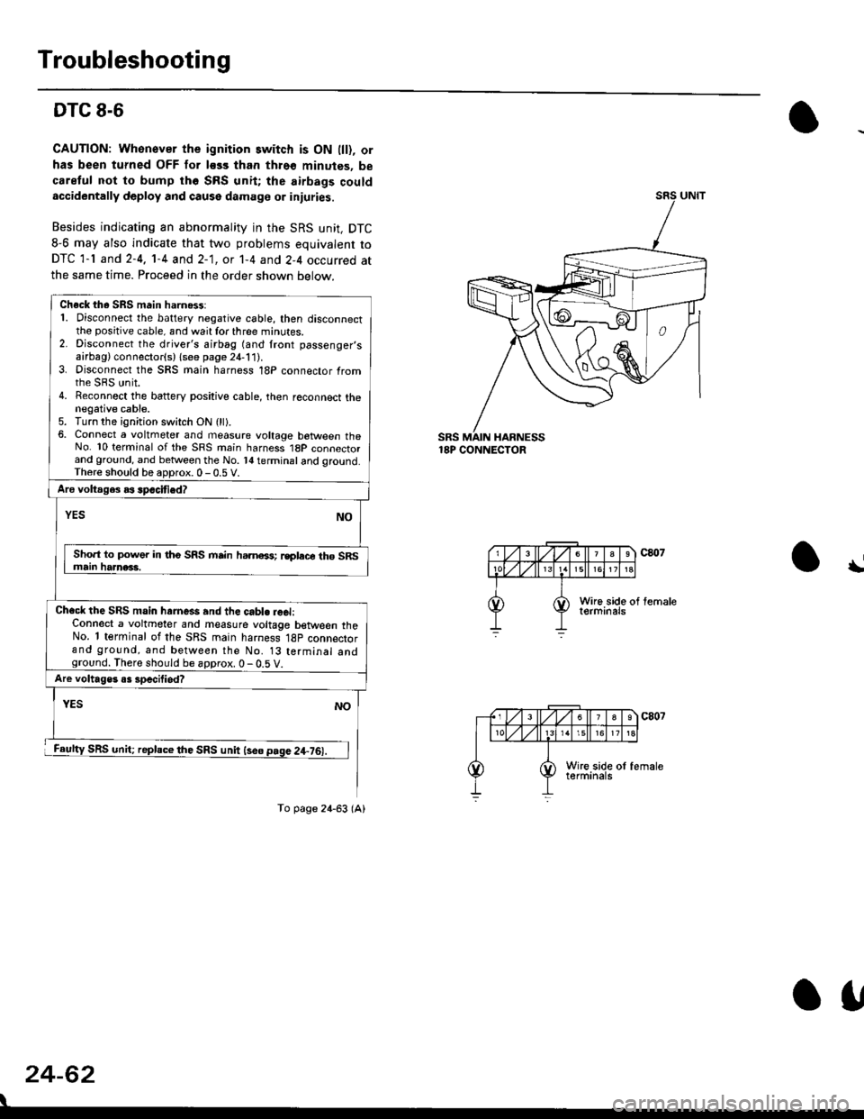
DTC 8-6
CAUTION: Whonover the ignition switch is ON lll), or
has been turned OFF for less than thro€ minutes, be
careful not to bump th6 SRS unit; the airbags couldaccidentally deploy and cause damage or iniuries.
Besides indicating an abnormality in the SRS unit, DTC
8-6 may also indicate that two problems equivalent to
DTC 1-l and 2-4, 1-4 and 2-1, ot 1-4 and 2-4 occurred at
the same time. Proceed in the order shown below.
SRS MAIN HARNESS18P CONNECTOR
\
24-62
Check th. SRS main harn6$:1. Disconnect the battery negative cable, then disconnectthe positive cable, and wait for three minutes.2. Disconnect the driver's airbag (and front passenger,sairbag) connector(s) {see page 21-111.3. Disconnect the SRS main harness 18P connector fromrhe sRS unit.4. Reconnect the battery positive cable, then reconnect thenegative cable.5. Turn the ignition switch ON (ll).6, Connect a voltmeter and measure voltage botween theNo. 10 terminal of the SRS main harness 1BP connectorand ground, and betlveen the No. l{ terminal and qround.Th6re should be aoDrox. 0 - 0.5 V.
Aro voltages as spacified?
NOYES
Sho.t to power in tho SRS mrin hamoss; rsplace th6 SRSmain haanac3.
Chacl the SRS main hrrne*s and the cabl. reel:Connect a voltmeter and measure voltage between theNo. 1 terminal of the SRS main harness 18p connectorand ground, and between the No. 13 terminal andground. There should be approx. 0 - 0.5 V.
Are voltages o3 specilied?
YES
SRS unit; replace the SRS unit lse6 page 2+76).
NO
To page 24-63 (A)
o1,
Page 1802 of 2189
Troubleshooting
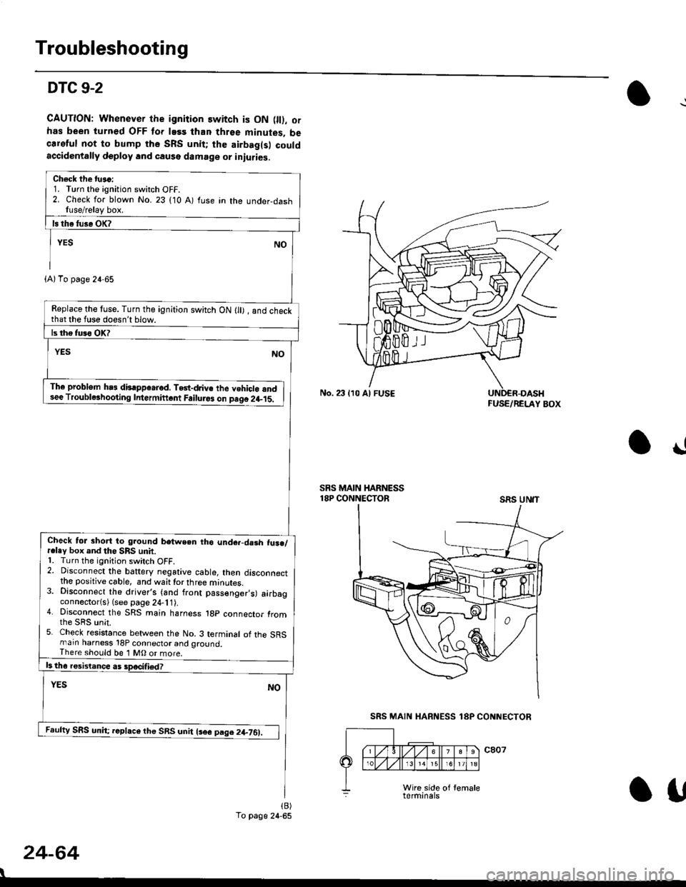
DTC 9-2
CAUTION: Whenever the ignition switch is ON 0l), ofhas been turned OFF lor lass than three minutes, becareful not to bump the SRS unit; the airbag(s) couldaccidentally deploy lnd caqse damage or iniuries.
Check the tu.c:1. Turn the ignition switch OFF.2. Check for blown No. 23 (10 A) fuse in the under,dashfuse/relay box.
Replace the tuse. Turn the ignition switch ON lll) , and checkthat the fuse doesn't blow.
Th6 problem hs3 disappe.rod, TGt-dJiv€ the vehiclo and3ee Troublerhooting Intermiftcnt Failuro3 on paqo 2l-15.
Check tol short to ground betwe.n tho unde.-da3h fus./r.ley box and the SRS unit.1. Turn the ignition switch OFF.2. Disconnect the baftery negative cable, then disconnectthe positive cable, and waittorthree minutes.3. Disconnect the driver's (and front passenger,s) airbagconnector(s) (see page 24-11).4. Disconnect the SRS main harness 1gp connector fromthe sRs unit.5. Check resistance between the No. 3 terminal of the SRSmarn harness 18P connector and ground,There should be 1 MO or more.
Feufty SRS unh; rcphce the SRS unit lsee pag.2+761.
(A)To page 24-65
To page 24-65
No. 23 lr0 Al FUSEFUSE/RELAY BOX
!
SRS MAIN HARNESS18P CONNECTORSRS UN'T
24-64
I
SRS MAIN HARNESS 18P CONNECTOR
Otf
Page 1804 of 2189
Troubleshooting
DTC 9-2 (cont'dl
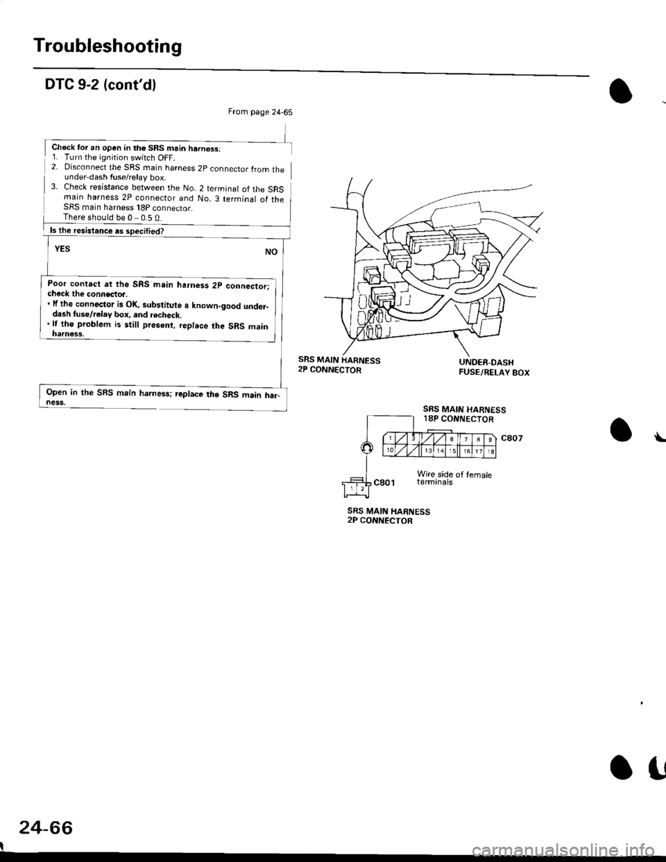
2- Disconnect the SRS rnain harness 2p connector lrom theunder-dash fuse/relay box.3- Check resistance between the No. 2 terminal of the SRSmain harness 2P connecior and No. 3 terminal of theSFS main harness 18P connector_
Poor contact at the SRS main ha.ness 2p connector;check the connecto... lf the connector is Ol(, sub3titute a known-good under-dash tuse/r€lay box, and recheck.'lt tho problem is still present, replece the SRS main
Open in the SBS main harness; replace the SRS main har_ness,
SRS MAIN HARNESS2P CONNECTOR
24-66
I
\
From page 24-65
Chock tor an open in th€ SRS main hern€ss:1. Turn the ignition switch OFF.
There should be 0 0.5 0
SRS MAIN
SRS MAIN HARNESS18P CONNECTOR
o!
Page 1818 of 2189
How To Use This Manual
The next few pages describe how this manual is organized. They also
explain what kind of information the manual contains, what that
informalion means, and how to use it to troubleshoot electrical problems.
Circuit schematics break the entire electrical system into individual
systems, like the Low Fuel lndicator Light on the nelit page.
Only electrical components that work together are shown together,
so you won't be distracted by unrelated wires.
Explanations of the abbreviations and svmbols used in the schematics
begin on page [Fl. You'll need to know what they mean before you can use
a schematic effectively.
Page 1821 of 2189
How To Use This Manual
Power Distribution Schematics (cont'd)
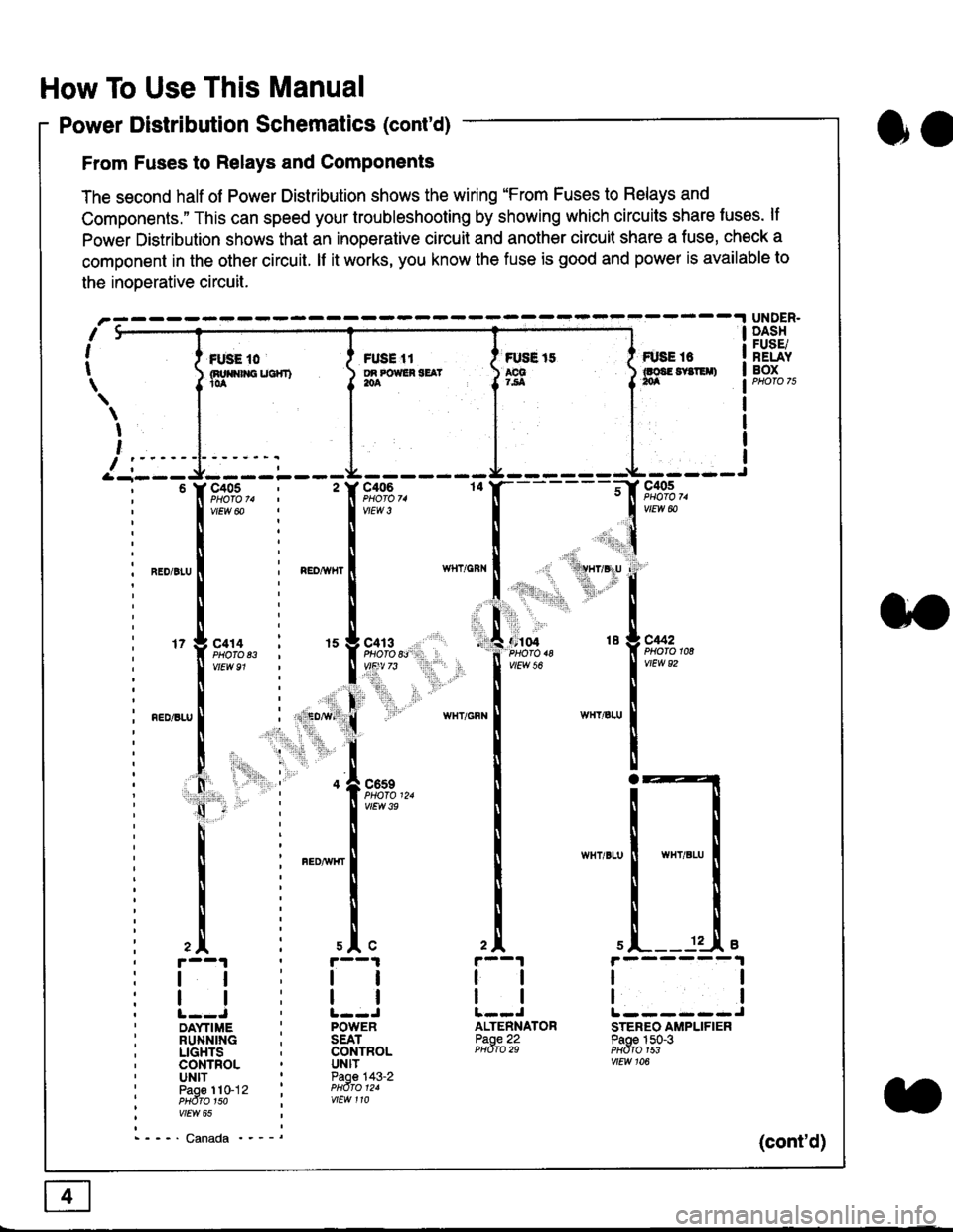
From Fuses to Relays and Components
The second half of Power Distribution shows the wiring "From Fuses to Relays and
Components." This can speed your troubleshooting by showing which circuits share luses. lf
Power Distribution shows thal an inoperative circuit and another circuit share a fuse, check a
component in the other circuit. lf it works, you know the fuse is good and power is available to
the inoDerative circuit.
oa
UNDER.DASHFUSE/RELAYBOXI i *. to i ru..'.' l * tt I tust tt
){nuo$rouc}rr) }g*"""' }tS }ff***,
\
I
,
I-- - ----\&- -----J-------ir
9,s9:,.,
,.,'li"'"rr' ' 'rll$vryglu
:
]:l. ,' "'':r.,
,:ti. .:1,,.,
*_lu*'.
'71ffi"�
- -t**,-
vtEw &
04 18 g C442
2A
tl
12 .L e
tl
ALTENNATORPaoe 22PHdro 29
ll
tlL------JSTEREO AMPLIFIERPaoe 150-3PHdfo 1s3vtEw 106
121
'f,"c;93,. : '� f,t'ffi
lv'Ew6o ! 1,.",
l:lN'll
^.o,r.u I i ".o,*", I
l:t
l,l
u*,.11,2", i "l9*',g
11""" : l*'-
l:lnEDisLu
|
; . ED,w' (
I'lP:ll
! " : .1".,9t3
q - '
I v'Ew3e
h;ll
l:ll
I : FED^rir{r
i
l:i
tii
,.L i slc
r--1 : r--1
tt:ll
ltlllt--J ' l--JDAYTIME : POWERRUNNING ; SEATLIGHTS . CONTROLCONTROL . UNITUNIT ' Paoe 143-2paoe 1to-j2 t PHdro t2.PHdTo 1so i wEw 110vtEw 65
- - -' Canada '_ _ _(cont'd)
Page 1828 of 2189
Five-Step Troubleshooting
L Verify The Complaint
Turn on all the components in the problem
circuil lo check the accuracy of the customer
complaint. Note the symptoms. Do not begin
disassembly or testing until you have
narrowed down the problem area.
2. Analyze The Schematic
Look up the schematic for the problem
circuit. Determine how the circuit is
supposed to work by tracing the current
paths lrom the power source through the
circuit components to ground. Also, trace
circuits that share wiring with the problem
circuit. The names of circuits that share the
same fuse, ground, or switch, and so on, are
referred to in each circuit schematic. Try to
operate any shared circuits you didn't check
in step 1 . lt the shared circuits work, the
shared wiring is OK, and the cause must be
in the wiring used only by the problem
circuit. lf several circuits fail at the same
time, the fuse or ground is a likely cause.
Based on the symptoms and your
understanding of the circuit's operation,
identify one or more possible causes.
3. lsolate The Problem By Testing The Circuit
Make circuit tests to check the diagnosis
you made in step 2. Keep in mind that a
logical, simple procedure is the key to
efficient troubleshooting. Test for the most
likely cause of failure first. Try to make tests
at points that are easily accessible.
4. Fix The Problem
Once the specific problem is identified,
make the repair. Be sure to use proper tools
and safe procedures.
5. Make Sure The Circuit Works
Turn on all components in the repaired
circuit in all modes to make sure you've
fixed the entire problem. ll the problem was
a blown fuse, be sure to test all of the
circuits on that fuse. Make sure no new
problems turn up and the original problem
does not recur.
Test Equipment
Most circuits include solid-state devices.
Test the voltages in these circuits only with
a 1o-megaohm or higher impedance digital
mUltimeter. Never use a test light or analog
meter on circuits that contain solid-state
devices. Damage to the devices may result.
Test Light and DVOM
On circuits without solid-state devices, use a
test light to check for voltage. A test light is
made up of a 12 volt bulb with a pair of leads
attached. After grounding one lead, touch the
other lead to various points along the circuit
where voltage should be present. The bulb
will go on if there is voltage at the point being
tested. lf you need to know how much
voltage is present, use a digital
volVohmmeter (DVOM).
Self-Powered Test Light and DVOM
Use a self-powered test light to check for
continuity. This tool is made up of a light bulb,
battery, and tlvo leads. To test it, touch the
leads together: the light should go on.
Use a self-powered test light only on an
unoowered circuit. First, disconnect the
battery, or remove the fuse that feeds the
circuit you are working on. Select two points
in the circuit belween which you want to
check continuity. Connecl one lead of the
self-powered test light to each point. lf there
is continuity, the test light's circuit will be
completed, and the light will go on.
SELF-POWERED TEST LIGHT
lf, in addition, you need lo know exacW hc'.
much resistance there is between two oo'^=
use a digital volUohmmeter (DVOM)
acdrt'Cn
t1