1998 HONDA CIVIC battery
[x] Cancel search: batteryPage 1736 of 2189
Power Door Locks
Transmitter Test
NOTE:
. lf the doors unlock or lock with the transmitter, but
the LED on the transmitter does not come on, the
LED is faulty; replace the transmitter.
. lf any door is open, you cannot lock or unlock the
door with the transmitter.
. lf you unlocked the doors with thetransmitter, but do
not open any of the doors within 30 seconds, the
doors relock automatically.
. The doors do not lock or unlock with the transmitter
if the ignition key is inserted in the ignition switch.
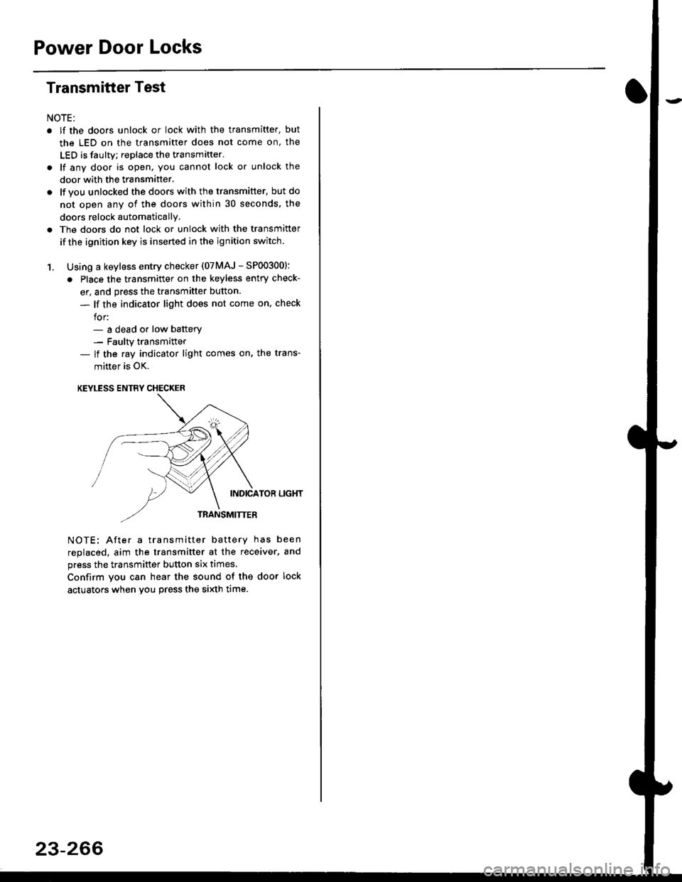
1. Using a keyless entry checker (07MAJ - SP003001:
. Place the transmitter on the keyless entry check-
er, and press the transmitter button.
- lf the indicator light does not come on, check
for:- a dead or low batterv- Faulty transmitter- lf the ray indicator light comes on, the trans-
mitter is OK.
KEYLESS ENTRY CHECKER
INDICATOR LIGHT
TRANSMITTER
NOTE: After a transmitter battery has been
replaced, aim the transmitter at the receiver, and
press the transmitter button six times,
Confirm you can hear the sound of the door lock
actuators when vou press the si)dh time.
23-266
Page 1743 of 2189
Description
)
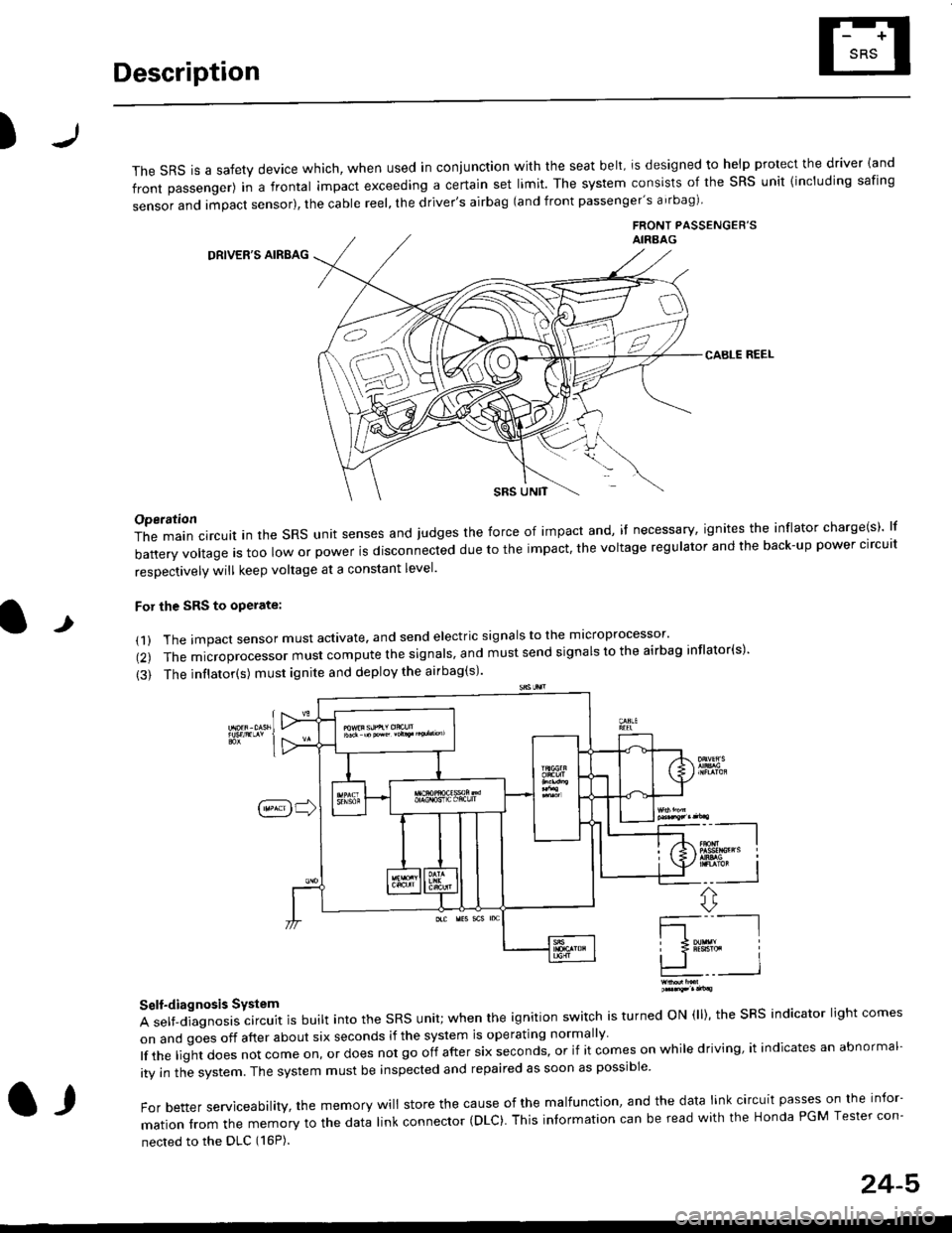
The sRS is a safety device which, when used in coniunction with the seat belt, is designed to help protect the driver land
front passenger) in a frontal impact exceeding a certain set limit. The system consists of the sRS unit {including safing
sensor and impact sensor), the cable reel, the driver's airbag (and front passenger's airbag)
FRONT PASSENGEB'SAIRAAG
DRIVER'S AIRBAG
CABLE REEL
SRS UNtT
t
Operation
The main circuit in the SRS unit senses and judges the force of impact and, if necessary, ignites the inflator charge(s) lf
battery voltage is too low or power is disconnected due to the impact, the voltage regulator and the back-up power clrcult
resoectivelv will keep voltage at a constant level.
For the SRS to operate:
(1) The impact sensor must activate. and send electric signals to the mlcroprocessor'
(2) The microprocessor must compute the signals' and must send signals to the airbag inflator(s)'
{3) The inflator(s) must ignite and deploy the airbag(s)'
_"-_-l
Ir3B!#h i
!.. I
ffi,*
Self-diagnosis System
A self-diagnosis circuit is built into the SRS unit; when the ignition switch is turned ON (ll), the SRS indicator light comes
on and goes off after about six seconds if the system is operating normally
lf the liglt does not come on, or does not go off after six seconds, or if it comes on while driving, it indicates an abnormal-
ity in the system. The system must be inspected and repaired as soon as possible
For better serviceability, the memory will store the cause of the malfunctlon, and the data link circuit passes on the infor-
mation from the memory to the data link connector (DLC). This intormation can be read with the Honda PGM Tesler con-
nected to the DLC (16P).
l,
24-5
Page 1745 of 2189
Precautions/ Procedures
)General Precautions
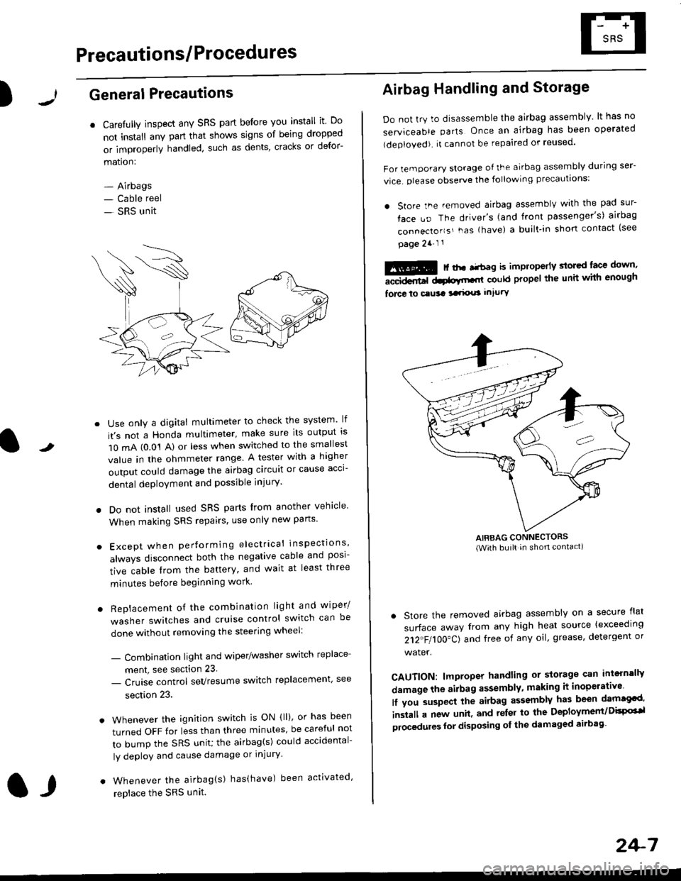
r Carefully inspect any SRS part before you install it Do
not install any part that shows signs of being dropped
or improperly handled' such as dents, cracks or defor-
mation:
- Airbags- Cable reel
- SRS unit
-
Use only a digital multimeter to check the system lf
it's not a Honda multimeter, make sure its output ls
1O mA (0.01 A) or less when switched to the smallest
value in the ohmmeter range. A tester with a higher
output could damage the airbag circuit or cause acci-
dental deployment and possible injury'
I Do not install used SRS parts from another vehicle
When making SRS repairs, use only new pans'
) Except when performing electrical inspections'
always disconnect both the negative cable and posl-
tive cable from the battery, and wait at least three
minutes before beginning work
r Replacement of the combination light and wiper/
washer switches and cruise control switch can be
done without removing the steering wheel:
- Combinalion light and wiper/washer switch replace
ment, see section 23
- Cruise control sevresume switch replacement' see
section 23.
. Whenever the ignition switch is ON {ll), or has been
turned OFF for less than three minutes' be careful not
to bump the SRS unit; the airbag(s) could accidental-
ly deploy and cause damage or injury'
. Whenever the airbag{s) has(have) been activated'
replace the SRS unit.l,
2+7
Airbag Handling and Storage
Do not try to disassemble the airbag assembly. lt has no
serviceable parts Once an airbag has been operated
(deployed). it cannot be repaired or reused'
For temporary storage of the airbag assembly during ser-
vice. olease observe the following precauttons:
. store the .emoved airbag assemblv with the pad sur-
face uo The driver's (and front passenger's) airbag
connecto''s'-as {have) a built.in short contact (see
page 2a-l 1
: | ..r r-+r-a k imninncrlv slorcd lace down,-""dd.r6t dtatltt-,tl could propel the unit whh enough
force lo c.usa 3a.ix! intury
AIRBAG CONNECTORS(With built in shon contact)
. Store the removed airbag assembly on a secure flat
surface away from any high heat source {exceeding
212"FI1OO"CJ and free of any oil' grease, detergent or
water.
CAUTION: lmproper handling or storage can intern'lJy
damage the airbag assembly, making it inoperativo
lf you suspect the airbag assembly has been dam€cd'
inslall a new unit. and relsr lo the Deployment/DisPG'l
olocedules for disposing ol the damaged airbag
Page 1749 of 2189
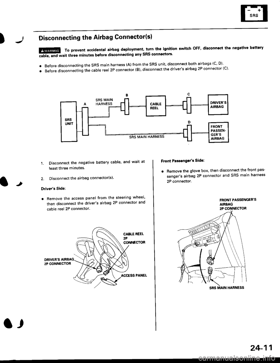
)Disconnecting the Airbag Connector(sl
'1. Disconnect the negative battery cable, and wait at
least three minutes.
2. Disconnect the airbag connector(sl.
Driver's Side:
. Remove the access panel from the steering wheel'
then disconnect the driver's airbag 2P connector and
cable reel 2P connector.
!@@ To prevent sccidental 8irbag deployment, turn th€ ignition switch oFF. disconncct th€ negative battery
ffi, "nd *"it thr"e minutes b€fore disconnocting any sRS conn'ctors'
. Before disconnecting the SRS main harness (A) from the SRS unit' disconnect both airbags (C' D)'
.Beforedisconnectingthecab|ereel2Pconnector(B),disconnectthedriver,sairbag2Pconnector(c).
F ont PasEanga/3 Side:
. Remove the glove box. then disconnect the front pas-
senger's airbag 2P connector and SRS main harness
2P connector.t
FRONT PASSENGER'SAIRBAG2P CONNECTOR
CABTT REEL2?CONNECTOR
AOCESS PANEL
a,
24-11
Page 1750 of 2189
Precautions/Procedu res
Steering-related Precautions
Stesring Wheel and Cable Reol Alignment
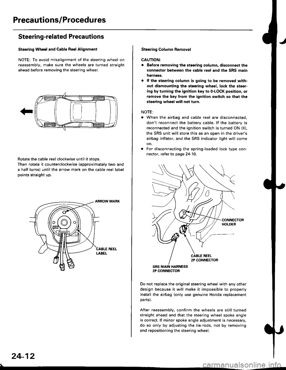
NOTE: To avoid misalignment of the steering wheel on
reassembly, make sure the wheels are turned straight
ahead before removing the steering wheel.
Rotate the cable reel clockwise until it stops.
Then rotate it counterclockwise {approximately two and
a half turns) until the arrow mark on the cable reel label
points straight up.
24-12
:l
St€€rin9 Column Removal
CAUTION:
. Eefore removing thg stggring column. disconnect the
connsstor bqtween the cable r€el and th€ SRS msin
harness.
. lf the stoering column is going to be romoved with-
out dismounting th6 stoering wheel, lock the steer-
ing by turning the ignition key to o-LOCK position, or
remove the key trom the ignition switch so that the
steering wheel will not turn.
NOTE:
When the airbag and cable reel are disconnected,
don't reconnect the battery cable. lf the battery is
reconnected and the ignition switch is turned ON (ll),
the SRS unit will store this as an open in the driver's
airbag inflator, and the SRS indicator light will come
on.
For disconnecting the spring-loaded lock type con-
nector, refer to page 24-'10.
SRS MAIN HARNESS2P CONNECTOR
Do not replace the original steering wheel with any other
design because it will make it impossible to properly
install the airbag (only use genuine Honda replacement
parts).
After reassembly, confirm the wheels are still turned
straight ahead and that the steering wheel spoke angle
is correct. lf minor spoke angle adjustment is necessary,
do so only by adjusting the tie-rods, not by removing
and repositioning the steering wheel.
Page 1751 of 2189
rl
Troubleshooting
t)
Self-diagnostic Procedures
The self-diagnostic function of the SRS system allows it to locate the causes of system problems and to store this informa' I
tion in memory. For easier troubleshooting, this data can be retrieved via a data link circuit l
. When you turn the ignition switch ON (ll), the SRS indicator will come on. ll it goes off after six seconds. the system is
norma l.
. lf there is an abnormality, the system locates and defines the problem, stores this information in memory, and turns
the sRS indicator light on. The data will remain in the memory even when the ignition switch is turned off or if the bat-
tery is disconnected.
o when you connect the scs service connector to the service check connector (2P), and turn the ignition switch oN (ll),
thesRsindicator|ightwi||indicatethediagnostictroub|ecode(DTC)bythenumberofb|inks.
. After reading and recording the DTC. proceed with the troubleshooting for this code'
Precauiions
.Useon|yadigita|mU|timetertocheckthesystem'|fit,snotaHondamu|timeter,makesureitsoutputisl0mA(0.01A)
or|esswhenSwitchedtothesma||estva|ueintheohmmeterrange,AtesterwithahigheroUtpUtcoulddamagethe��
airbag circuit or cause accidental airbag deployment and possible injury'
r when-ever the ignition switch is oN (ll). or has been turned oFF for lessthan three minutes, be careful nottobumpthe
SRS unit; the airbags could accidentally deploy and cause damage or injuries
. Before you ,"n1ou" th" SRS main harness, disconnect the driver's airbag connector (and the front passenger's airbag
connector).
. Make sure the battery is sufficiently charged {see section 23}. lf the battery is dead or low, measuring valLles won t be
correct.
. Do not touch a tester probe to the terminals in the sRS unit or harness connectors, and do not connect the terminals
with a jumper wire. Use only the backprobe set or the special tools'
For backprobing spring-loaded lock type connectors, refer to page 24-9'
Reading the DTC
when the SRS indicator light is on, read the DTC using one of these methods:
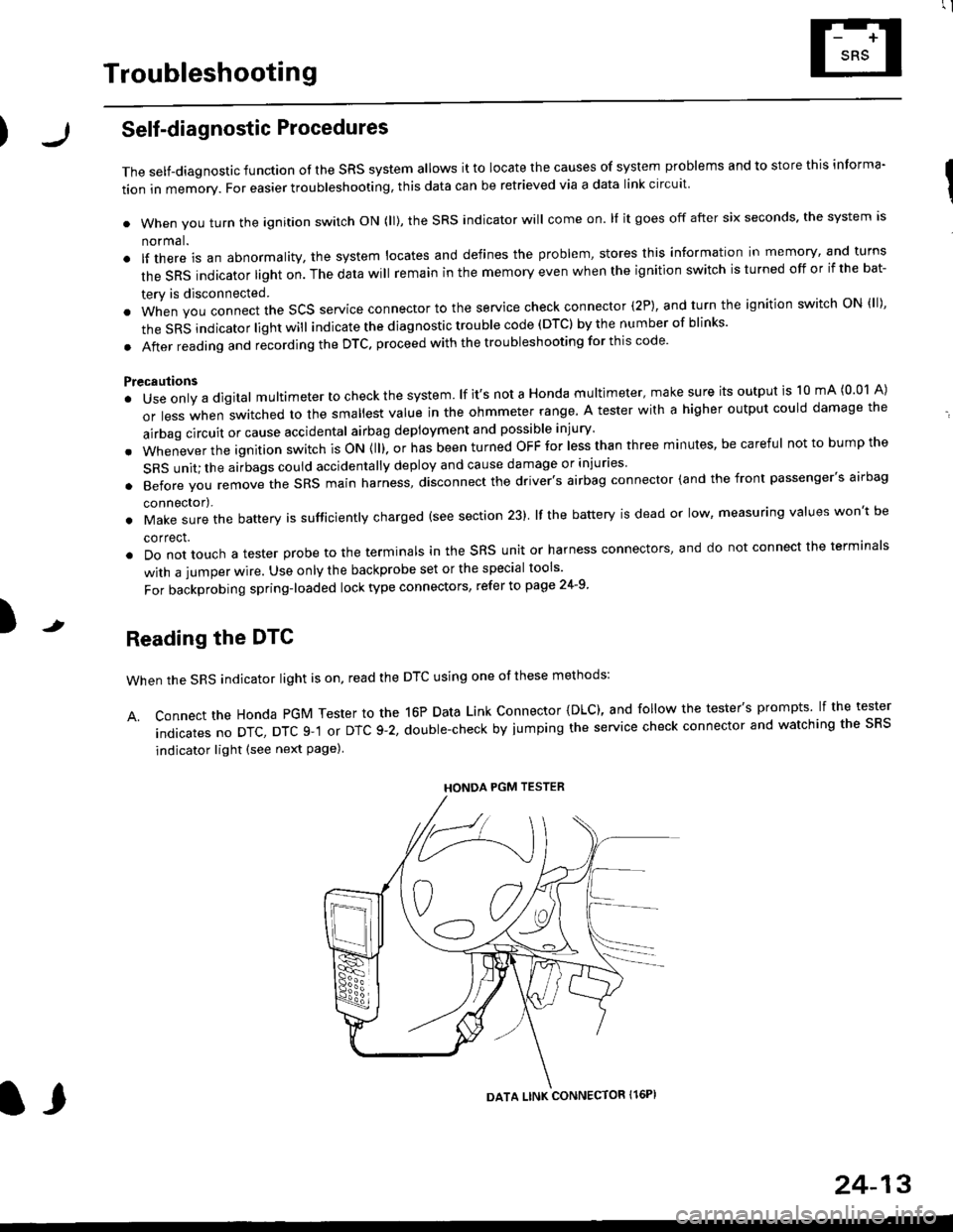
A. Connect the Honda PGM Tester to the 16P Data Link Connector {DLC), and follow the tester's prompts lf the tester
indicatesnoDTc,DTcg-1orDTc9-2,doub|e-checkbyjumpingtheservicecheckconnectorandwatchingthesRS
indicator light (see next Page)
HONDA PGM TESTER
DATA LINK CONNECTOR Il6PI
l,
24-13
Page 1767 of 2189
)The SRS lndicator Light Doesn't Go Off -'96 - 97 Models
CAUTION: Whenever the ignition switch is ON (ll), or has been turned OFF for less than three minutes, be careful not to
bump the SRS unit; the airbag{sl could accidentally deploy and cause damage or iniuries
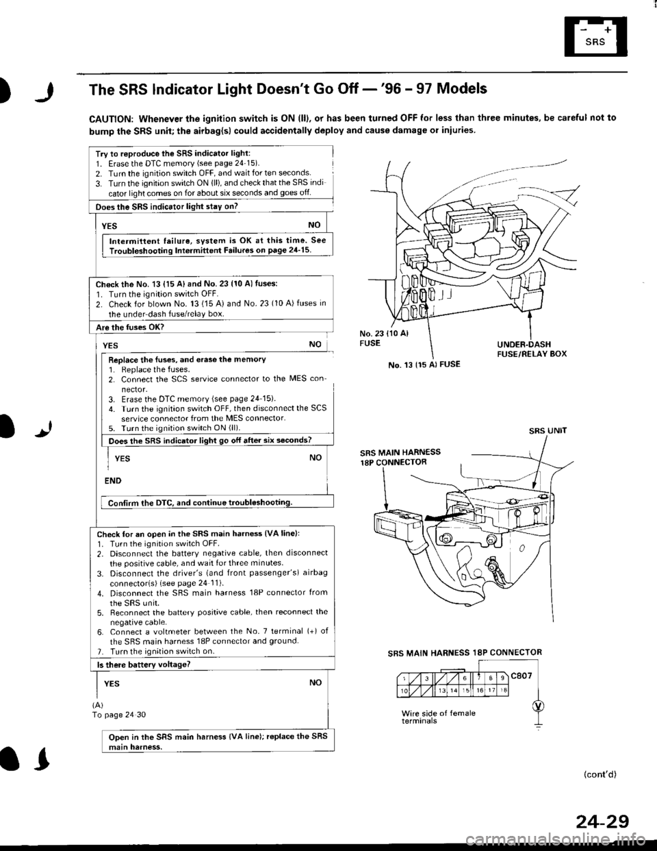
Try to reproduce lhe SRS indicator light:
1. Erase the DTC memory (see page 24'15).
2. Turn the ignition switch OFF, and wait for ten seconds.
3- Turn the ignition switch ON {ll), and check that the SRS indi
cator light comes on for about six seconds and goes off
Does the SRS indicEtor light stay on?
[*NO
Intermittent lailure, system is OK at this time. See
Troubloshooting Int6rmittent Failures on page 24'15
Ch€ck the No. 13 {15 A} and No. 23 (10 A) fuses:
1. Turn the ignition switch OFF.
2. Check for blown No. 13 (15 A) and No.23 (10 A)fuses in
the under dash fuse/relay box.
Are the fuses OK?
vEs No
Replace the luses, and erase the memory1. Replace the fuses.2. Connect the SCS service connector to the MES con
nector.3. Erase the DTC memory (see page 24 15).
4. Turn the ignitaon switch OFF, then disconnect the SCS
service connector from the MES connector.5. Turn the ignition switch ON (ll).
Does the sRS indicato, tigt t go or "ne. "ii--JJl
-I YEs NO1
ENDi
Conlirm the DTC, and continue troubl6shootilg.
Check for an open in the SRS main harness {VA linell'1. Tu.n the ignition switch OFF.
2. Disconnect the battery negative cable, then disconnect
the positive cable, and wait for three minutes.
3. Disconnect the driver's (and front passenger's) airbag
connectorls) (see page 24 11).
4. Disconnect the SBS main harness '18P connector from
the sRS unir.5, Reconnect the battery positive cable, then reconnect the
negative cable.6. Connect a voltmeter between the No. 7 tetminal (+) of
the SRS main harness 18P connector and ground.
7. Turn the ignition switch on.
b there battery voltageT
YESNO
(A)
To page 24 30
Open in the SRS main harness IVA line); replace the SRS
main harness.
l.J
SBS MAIN
(cont'd)
No. 't3 {15 Al FUSE
SRS UNIT
HARNESS 18P CONNECTOR
II
24-29
Page 1772 of 2189
Troubleshooting
The SRS Indicator Light Doesn't Go Off -'98 - 00 Models
CAUTION: Whenever the ignition switch is ON {ll}, orhas b66n turned OFF for less than three minutes, becareful not to bump the SRS unit; the airbags coutdaccidentally deploy and cause damage or iniuries.
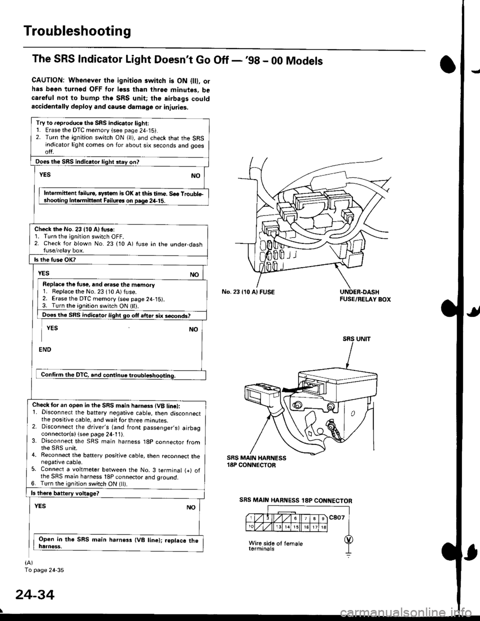
No. 23 {10 Al FUSEFUSE/RELAY BOX
SRS MAIN HARNESS 18P CONNECTOR
Try to reproduce the SRS indic.tor light:1. Erase the DTC memory (see page 24-15).2. Turn the ignition switch ON (lt), and check that the SRSindicator light comes on for about six seconds and ooesol1.
Intormittent lailulo, systom is OK atthistime. Soo Troublel. o.mittgnl Failuros on paqe24-15.
Check the No. 23 (10 Alfuse:1. Turn the ignition switch OFF.2. Check for blown No. 23 (10 A) tuse in the under,dashfuse/relay box.
Replace ihe fus€, and 6.ase the momory1. Replace the No. 23 110 A) fuse.2. Erase the DTC memory (see page 24,15).3. Turn the ignition switch ON (ll).
Doos the SRS indicator light go off after 3ix second3?
Check tor an open in the SRS msin harness {VB lincl:1. Disconnect the battery negative cable, then disconnectthe positive cable, and wait tor three minutes.2. Disconnect the driver's (and front passenger,s) airbagconnector(s) (see page 24-11).3. Disconnect the SRS main harness 18p connector Iromthe sRs unit.4. Reconnect the battery positive cable, then reconnect thenegative cable.5. Connect a voltmeter between the No. 3 terminal (+) ofthe SRS main harness 18P connector ano qrouno.6. Turn the ignition switch ON {ll).
(A)
To page 24-35
24-34