Page 1404 of 2189
Troubleshooting -'99 - 00 Models
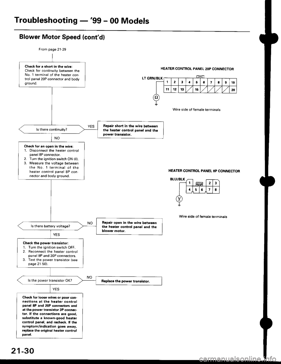
Blower Motor Speed (cont'dl
HEATER CONTROL PANEL 2OP CONNECTOR
Wire side oJ female terminals
Wire side ot female terminals
Frcm page 21.29
LT GRN/BLK
Check tor a short in the wi.a:Check for continuity between theNo. 1 terminal of the heater control panel 20P connector and bodyground.
Repair short in ths wire betwsenthe hoater control panel and theoower transastoa.
Check for an open in the wire:1. Disconnect the heater controlpanel 8P connector,2. Turn the ignjtion switch ON 1ll).3. Measure the voltage betweenthe No. 'l terminal of theheater control panel 8P connector and body ground.
Repeir open in the wiio betweenthe heater control panel and theblower motoa.
Check the power transistor:1. Turn the ignition switch OFF.2. Reconnect the heater controlpanel 8P and 20P connectors.3. Test the power transistor {seepage 21 50).
ls the power transistor OK?
Check for loos€ wiras or poor con-nections at the h€at€r controlpanel 8P and 20P connectols andat th6 power transistor 3P conn€c-tor. lf the connections are good,substituto a known-good hoatercontrol panel, and recheck. It thesymptom/indication goes away,replace the original heater controloanel,
HEATER CONTNOL PANEL 8P CONNECTOR
21-30
Page 1406 of 2189
Troubleshooting -'99 - 00 Models
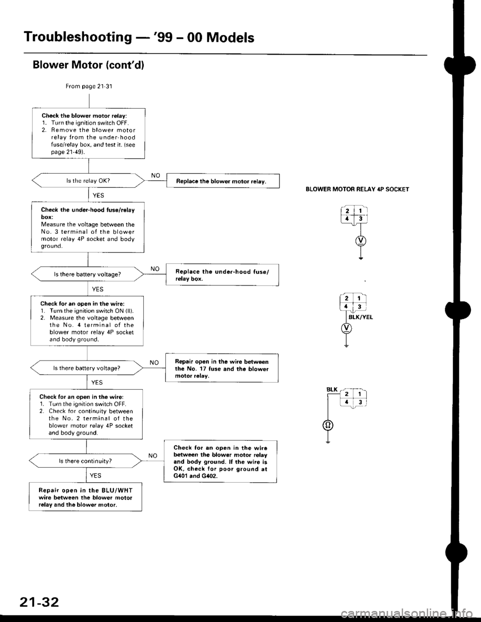
From page 21-31
Check the blower motor relay:1. Turn the ignition switch OFF.2. Remove the blower motorrelay from the under hoodfuse/relay box, and test it- (seepage 21'49).
Replace the blower motor relay.
Check the under-hood tuse/relaybox:Measure the voltage between theNo. 3 terminal of the blowermotor relay 4P socket and bodyground.
Check tor an open in the wire:1. Turn the ignition switch ON (ll).
2. Measure the voltage betweenthe No. 4 terminal of theblower motor relay 4P socketand body ground.
Repair opon in lhe wire betweenthe No. 17 fuse and the blowetls there battery voltage?
Check for an open in the wire:1. Turn the ignition switch OFF.2. Check for continuity betweenthe No. 2 terminal of theblower motor relay 4P socketand body ground.
Check lor an ooen in the wirebetween the blowor motor relayand body ground. It the wiie isOK, check for poor ground atG401 and G402.
ls there continuityl
Repair open in the BLU/WHTwiae between the blower motorrelay and the blower motor,
BLOWER MOTOR RELAY 4P SOCKET
21-32
Page 1408 of 2189
Troubleshooting -'99 - 00 Models
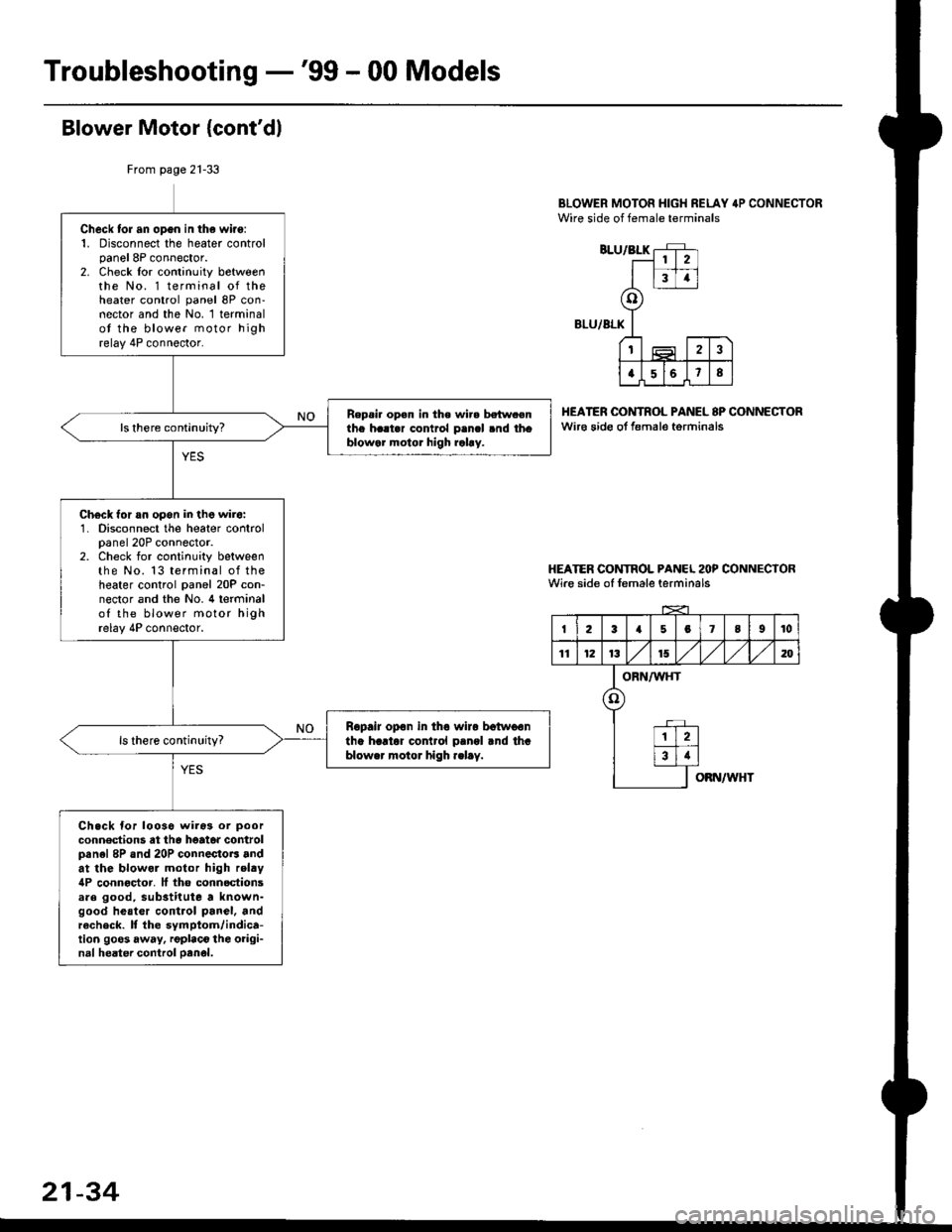
Blower Motor {cont'dl
BLOWER MOTOR HIGH RELAY 4P CONNECTORWire side of female terminals
BLU/BLK
BLU/ALK
HEATER OONTROL PANEL 8P CONNECTORwir€ sido ot f€male torminals
HEATER CONTROL PANCL 2OP CONNECTORWire side of female terminals
From page 21-33
Check tor an opgn in the wiro:1. Disconnect the heater controlpanel 8P connector.2. Check lor continuity betweenthe No. 1 terminal of theheater control panel 8P con-nector and the No. 1 terminalot the blower motor highrelay 4P connector.
Repsi. op€n in the wir. betw.enthe h..t.r contrcl p.ncl .nd thoblowar motor high rahy.
Ch€ck for an opon in the wir6:1. Disconnect the heater controlpanel 20P connector.2. Check for continuity betweenthe No. 13 terminal of theheater control panel 20P con-nector and the No. 4 terminalof the blower motor highrelay 4P connector.
Ropair opon in tho wiro botwoontha hartor cor rol pangl rnd thablower motor high .elay.
Ch.ck for looso wiros or poor
conn€dions at th6 heato. controlpanel 8P and 20P connectoB andat the blowol motor high relty4P connoctor. It tho connoctionsare good, substitute a known-good heatcr control panel, andrecheck. It the symptom/indica-tion goos away, rgplaco the oiigi-nal heater control oanol.
2
34
o
t2
a568
I23a5078I10
11121315,/1,/1,/m
ORN/WHT
o
12
34
OBN/WHT
21-34
Page 1410 of 2189
Troubleshooting -'99 - 00 Models
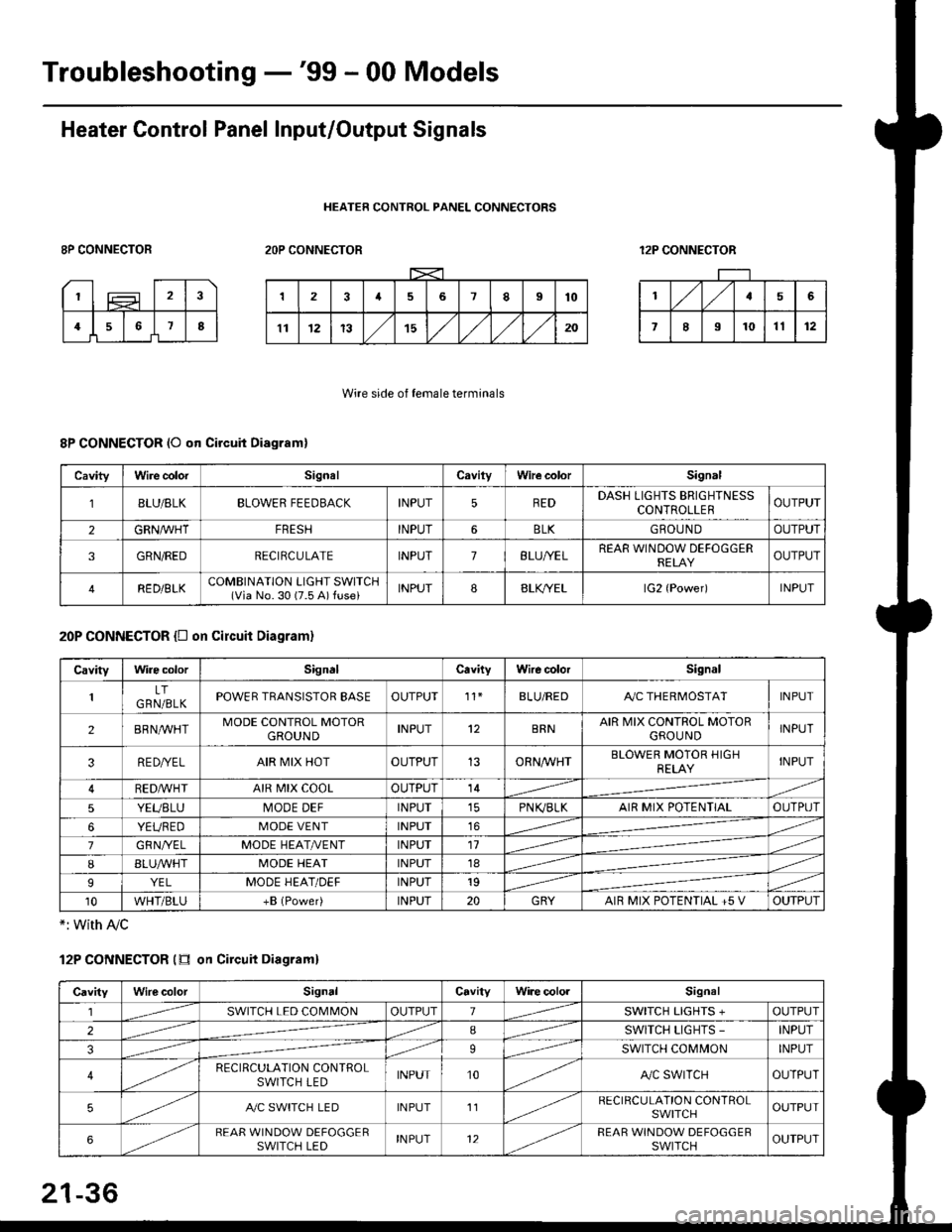
Heater Control Panel Input/Output Signals
HEATER CONTROL PANEL CONNECTORS
8P CONNECTOR2OP CONNECTOR12P CONNECTOR
Wire side of female terminals
8P CONNECTOR (O qn Circuit Diagram)
20P CONNECTOR {D on circuit Diagram}
*: with Ay'c
12P CONNECTOR (tr on Circuit Diagraml
CavityWire colorSignalCavilyWhe colorSignal
BLU/8LKBLOWER FEEDBACKINPUT5REDDASH LIGHTS BRIGHTNESSCONTROLLEROUTPUT
2GRN/lVHTFRESHINPUT6BLKGBOU N DOUTPUT
3GRN/REDRECIRCULATEINPUT7BLU/YELREAR WINDOW DEFOGGERRELAYOUTPUT
4RED/BLKCOMBINATION LIGHT SWITCH(Via No. 30 (7.5 A) fuse)INPUT88LfiELlG2 {Power)INPUT
CavityWire colorSignalCavityWire colorSignal
LTGRN/BLKPOWER TRANSISTOR EASEOUTPUT't1BLU/REDAy'C THERMOSTATINPUT
2BRNMHTMODE CONTROL MOTORGROUNDINPUT12BRNAIR MIX CONTROL MOTORGROU NDINPUT
3RE D/YELAIR MIX HOTOUTPUT13ORNAA/HTBLOWER MOTOR HIGHRELAYINPUT
RED,ryvHIAIR MIX COOLOUTPUT14
5YEUBLUMODE DEFINPUTPN K,/BLKAIR MIX POTENTIALOUTPUT
6YEUREDMODE VENTINPUT16
7GRNI/ELMODE HEAT/r'ENTINPUT11
IBLUAVHTMODE HEATINPUT18
9YELMODE HEAT/DEFINPUT19
10WHT/BLU+B (Power)INPUT20GRYAIR MIX POTENTIAL +5 VOUTPUT
CavityWilecolorSignalCavityWi.e cololSignal
lSWITCH LED COMMONOUTPUT1SWITCH LIGHTS +OUTPUT
2ISWITCH LIGHTS -INPUT
39SWITCH COMMONINPUT
4RECIRCULATION CONTROLSWITCH LEDINPUT10A,/C SWITCHOUTPUT
5A./C SWITCH LEDINPUT11RECIRCULATION CONTROLSWITCHOUTPUT
6REAR WINDOW DEFOGGERSWITCH LEDINPUT12REAR WINDOW DEFOGGEBSWITCHOUTPUT
21-36
Page 1425 of 2189
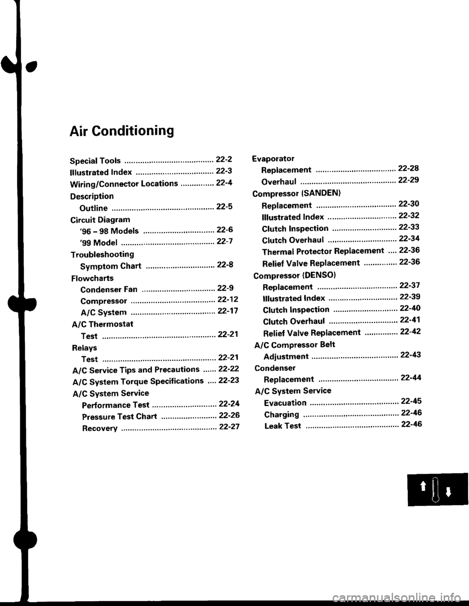
Air Conditioning
Speciaf Tools ......'.....' 22-2
f f f ustrated f ndex ......................... ".......' 22-3
Wiring/Connector Locations'.........'.... 22'4
Description
Outfine ............ .......22-s
Circuit Diagram
'96 - 98 Models ......"..........".......'.... 22-6
'99 Modef """""""' 22-7
Troubleshooting
Symptom Chart ".'......""................. 22-8
Flowcharts
Condenser Fan .........".................,..'. 22-9
Compressor .....""" 22-12
A/C System .........'.22'17
A/C Thermostat
Test ........'.......' """'22'21
Relays
Test ....."'......... ..""'22-21
A/C Service Tips and Precautions ......22-22
A/C System Torque Specifications '...22-23
A/C System Service
Performance Test ... '."......... ".... ....'..22-24
Pressure Test Chart .................. .... "' 22-26
Recovery ...".........," 22-27
Evaporator
Replacement .....",' 22'24
Overhauf .....-.....""' 22'29
Compressor {SANDEN}
Repf acement ......'.' 22-30
fffustrated fndex ......"..................'.... 22'32
Cf utch Inspection ......... "............ ...... 22-33
Clutch Overhau I ........................ ....... 22-34
Thermal Protector Replacement .... 22-36
Relief Valve Replacement ......'..."". 22-36
Compressor (DENSO)
Repfacement ..""',' 22-37
lf lustrated Index ............................... 22-39
Clutch lnspection ............."'...... "'.... 22-40
Cf utch Overhaul .....................'......... 22-41
Ref ief Valve Replacement'..'......"'.. 22-42
A/C Compressor Belt
Adiustment ............22'43
Condenser
Repfacement .......,,22'44
A/C System Service
Evacuation ...,,,.......22-45
Charging '..........--'..22'46
Leak rest """""""'22-46
Page 1432 of 2189
Troubleshooting
Symptom Chart
NOTE:
. Any abnormality must be corrected before continuing the test.. Because of the precise measurements needed. use a multimeter when testinq.. Before performing any troubleshooting procedures check:- Fuses No. 47 l7 -5 Al, No. 56 (20 A) in the under-hood fuse/relay box, and No. 17 (7.5 A) in the under_dash fuse/relavbox- Grounds No. c401, c402, G751- Cleanliness and tightness of alt connectors
SymptomRemedy
Condenser fan does not run at all.Perform the procedures in the flowchart {see page 22-9).
Compressor clutch does not engage.Perform the procedures in the flowchart lsee page 22-12).
Ay'C system does not come on (compressor and fan),Perform the procedures in the flowchan (see page 22-17).
Both heater and A,/C do not work.. '96 - 98 models-Perform the procedures in the flowchart
{see page 21-18).. '99 - 00 models-Perform the procedures in the flowchart(see page 21-35).
22-8
Page 1434 of 2189
Troubleshooting
Condenser Fan (cont'd)
CONDENSER FAN RELAY 4P SOCKET
CONDENSEB FAN 2P CONNECTORWire side of female terminals
-=F_
l!.lI slx
@I
Check tor an opon in the wi.o:1. Disconnect the jumper wire.2. oisconnect the condenser tan2P connector.3. Check for continuity betweenthe No. 1 terminal of the con-denser fan relay 4P socket andthe No. 1 terminal of the con-denser fan 2P connector.
Rapair op6n in the wirs bgtwconthe condcnsor tan rclay and thecondgnlar fan.
ls there continuity?
Check to. en open in the wire:Check for continuity between theNo. 2 terminal ot the condenserfan 2P connector and bodyground.
Check Ior rn opon in th6 wirebctwoen the condcnser tan andbody ground, lf iho wirc ii OK,chcck for poor ground at G751.
ls there continuity?
Replaco the condense. fan motor.
22-10
Page 1436 of 2189
Troubleshooting
Compressor
COMPRESSOR CLUTCH RELAY.P SOCKET
JUMPERWIRE
check the No. 56 (20 A) fuse in theunder'hood fuse/relay box, and theNo. 17 (7.5 A) fuse in the under,dash fuse/relay box.
Replace the fussls), and .echeck.
Remove the compressor clutchrelay, and test it {see page 22 21).
Check th6 und€r-hood tu3e/reby
Measure the voltage between theNo. 2 terminal of the compressorclutch relay 4P socket and bodyground.
Check the compressor clutchpow€r supply circuit:Connect the No. 1 and No. 2 termi-nals of the compressor clutch relay4P socket with a jumper wire.
Does the compressor clutch click?fo page 22-13
To page 22 14
22-12