1998 HONDA CIVIC wheel bearing
[x] Cancel search: wheel bearingPage 570 of 2189
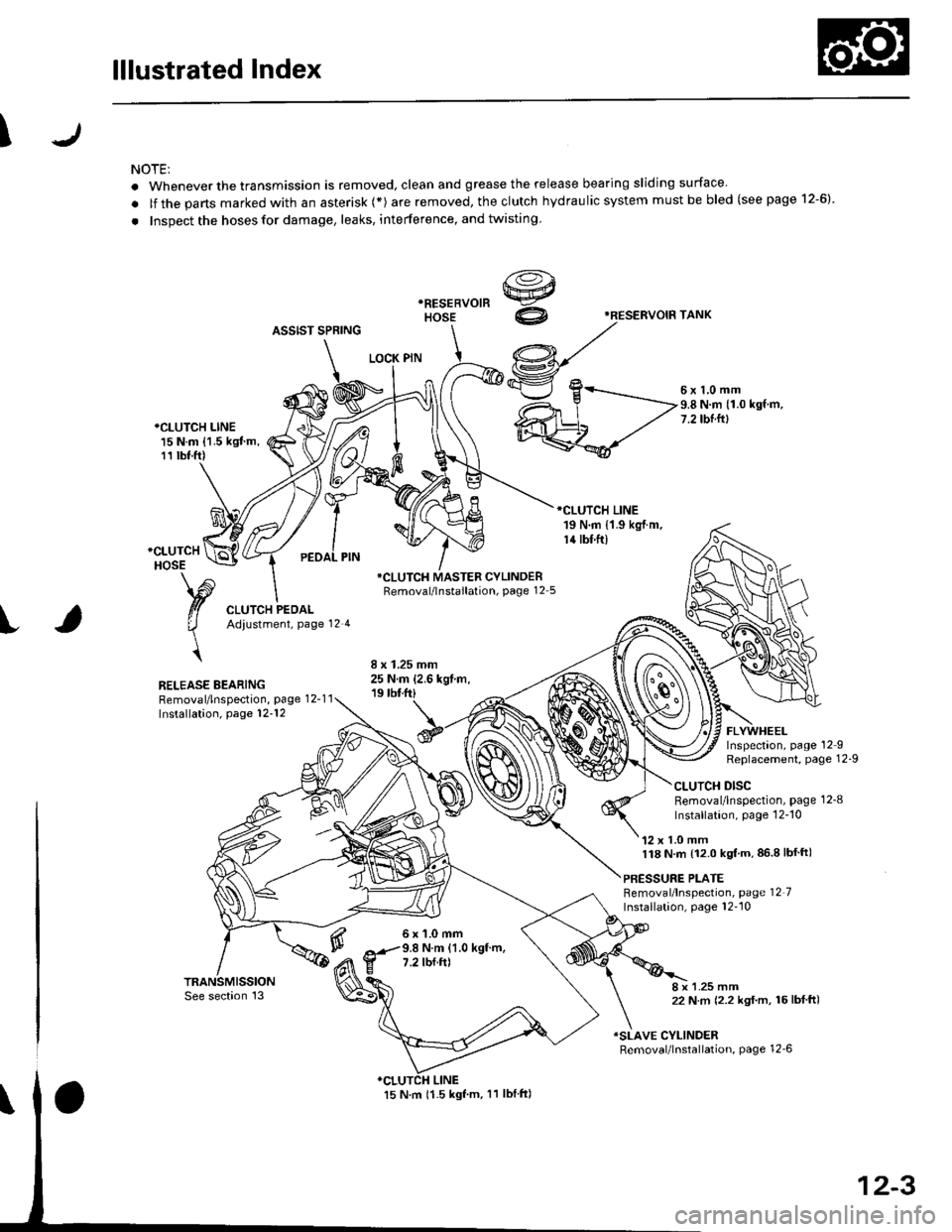
lllustrated Index
\
NOTE:
. Whenever the transmission is removed, clean and grease the release bearing sliding surface
. lf the parts marked with an asterisk (*) are removed, the clutch hydraulic system mustbe bled (seepage 12-6)
. Inspect the hoses for damage, leaks, interference, and twisting
'RESERVOIF TANK
ASSIST SPRING
LOCK PIN
5x1,0mm9.8 N.m (1.0 kgf.m,7.2 tbtftl*CLUTCH LINE15 N.m {1.5 kgJ m,11 tbt.ft)
RELEASE BEARINGRemoval/lnspection, page 12-1 1Installation, page 12-'12
*CLUTCH MASTER CYLINDERRemoval/lnstallation, page 12 5
6x1.0mm9.8 N.m (1.0 kgf.m,7.2 tbf.ft)
FLYWHEELInspectaon, page 12IReplacement, Page 12-9
CLUTCH DISCRemoval/lnspection, page 1 2-8
lnstallation, page 12-'10
'12 x 1.0 mm118 N.m {12.0 kgt'm,86.8lbfft)
PBESSURE PLATEBemoval/lnspection, page 12 7Installation, page 12''10
8 x 1.25 mm22 N m (2.2 kgf.m, 16lbf ft)
ISLAVE CYLINDERRemoval/lnstallation, page 12_6
12-3
Page 576 of 2189
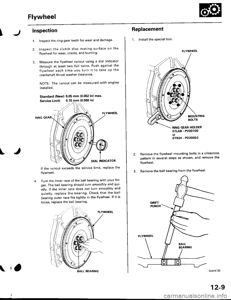
Flywheel
\Inspection
1.
2.
3.
Inspect the ring gear teeth for wear and damage
Inspect the clutch disc mating surface on the
flywheel for wear, cracks, and burning.
Measure the flywheel runout using a dial indicator
through at least two full turns Push against the
flywheel each time you turn it to take up the
crankshaft thrust washer clearance.
NOTE: The runout can be measured with engine
installed.
Standard (New): 0.05 mm (0.002 inl max.
Service Limit: 0.15 mm {0.006 in)
FLYWHEEL
OIAL INOICATOR
FLYWHEEL
lf the runout exceeds the service limit. replace the
flywheel.
Turn the inner race o{ the ball bearing with your tin-
ger. The ball bearing should turn smoothly and qui
etly. lf the inner race does not turn smoothly and
quietly, replace the bearing. Check that the ball
bearing outer race fits tightly in the flywheel. lf it is
loose. replace the ball bearing
IJ
4.
BALL BEARING tO
Replacement
1. Installthe special tool.
MOUNTINGBOLTS
RITIG GEAR HOLDER
oTLAB-PV00100oto7924-PD20003
2.Remove the flywheel mounting bolts in a crisscross
pattern in several steps as shown, and remove the
flywheel,
Remove the ball bearing from the flywheel
(cont'dl
12-9
FLYWHEEL
t\
m\J
Page 577 of 2189

FlywheelClutch Disc, Pressure Plate
Replacement (cont'dl
4. Drive the new ball bearing into the flywheel using
the special tools as shown.
DRIVER07749-0010000
ATTACHMENT,32x35mm07746-OOIOTOO
FLYWHEEL
BEARING
Align the hole in the flywheel with the crankshaft
dowel pin and install the flywheel. Install the
mounting bolts finger-ti9ht.
Install special tool, then torque the flywheel mount-
ing bolts in a crisscross pattern in several steps as
snown.
5.
6.
MOUNTING BOLTS118 N.m (12.0 kgl.m,87 tbf.ft)
RING GEAR HOLDER07LAB-PV00100ol07924 -PO20003
WVa// ,
12-10
Installation
1. Install the special tool.
Y
07936-3710r00
{P/N 08798-90021
RING GEAR HOLDER07LAB-PVOO100ot07924-PD20003
CLUTCH ALIGNMENT SHAFTOTJAF_PM7012A
2.
3.
Installthe clutch disc using the special tools.
Install the pressure plate.
RING GEAR HOLDERoTLAB PV00'l OO
07924 PD20003
OTJAF_PM70124HANOLE07936-3710100
CLUTCH DISC
Page 790 of 2189
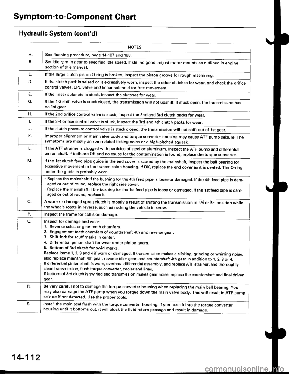
Symptom-to-Component Chart
Hydraulic System (cont'dl
G.
n,
set idle rpm in gear to specified idle speed. lf still no good, adjust motor mounts as outlined in enginesection of this manual.
lf the clutch pack is seized or is excessively worn. inspect the other clutches for wear, and check the orificecontrol valves, CPC valve and linear solenoid for free movement.
lf the linear solenoid is stuck, inspect the clutches for wear.
lmproper alignment or main valve body and torque converter housing may cause ATF pump seizure. Thesymptoms are mostly an rpm-related ticking noise or a high-pitched squeak.
lf the l st clutch feed pipe guide in the end cover is scored by the mainshaft, inspect the ball bearing forexcessive movement in the transmission housing. lf oK, replace the end cover as it is dented. The o-rinounder the guide is probably worn.
Replace the mainshaft if the bushing for the 4th feed pipe is loose or damaged. lf the 4th feed pipe is danFaged or out of round, replace the right side cover.
Replace the mainshaft if the bushing for the 1st feed pipe is loose or damaged. lf the 1st feed pipe is darn-aged or out of round, replace it.
A worn or damaged sprag clutch is mostly a result of shifting the transmission inthe wheels rotate in reverse, such as rocking the vehicle in snow.
or E position while
Inspect for damage and wear:
1. Reverse selector gear teeth chamfers.
2. Engagement teeth chamfers of countershaft 4th and reverse gear.
3. Shift fork for scuff marks in center.
4. Differential pinion shaft for wear u nder pin ion gears.
5. Bottom of 3rd clutch for swirl marks.
Replace items 1,2,3 and 4 if worn or damaged. lf transmission makes a clicking, grinding orwhirring noise,also replace mainshaft 4th gear, reverse idler gear. and countershaft 4th gear in addition to 1, 2, 3 or 4.lf differential pinion shaft is worn, overhaul differential assembly, and replace ATF strainer, and thoroughlyclean transmission, flush torque converter, cooler and lines.lf bottom of 3rd clutch is swirled and transmission makes gear noise, replace the countershaft and final drivengear.
Be very careful not to damage the torque converter housing when replacing the main ball bearing, you
may also damage the ATF pump when you torque down the main valve body. This will result in ATF pumpseizure if not detected. Use the oroper roors.
Install the main seal flush with the torque converter housing. lf you push it into the torque converterhousing until it bottoms out, it will block the fluid return passage and result in damage.
See flushing procedure, page 14-187 and 188.
lf the large clutch piston O-ring is broken, inspect the piston groove for rough machining.
lf the l-2 shift valve is stuck closed, the transmission will not upshift. lf stuck open, the transmission hasno 1st gear.
lf the znd orifice control valve is stuck. inspect the 2nd and 3rd clutch oacks for wear.
lf the 3-4 orifice control valve is stuck, inspect the 3rd and 4th clutch oacks for wear.
lf the clutch pressure control valve is stuck closed, the transmission will not shift out of 1st gear.
lf the ATF strainer is clogged with particles of steel or aluminum, inspect the ATF pump and differentialpinion shaft. lf both are OK and no cause for the contamination is found, replace the torque converter.
Inspect the frame for collision damage.
14-112
Page 871 of 2189

Continuously Variable Transmission (CVTI
Special Tools ................ 14-194
Description .................... 14-195
Clutches/Reverse Brake/Planetary
Gear/Pulleys .......... 14-198
power Flow ..............,..... 14-200
Electronic Control SYstem(,96 - 98 Modets) ......14-203
Electronic Control System
('99 - oo Models) " 14-205
Hydraulic Control '....... 14-208
Hydraulic Flow .'..-.....'... '14-212
Park Mechanism .....-...'.' 14-222
Eleqtrical Systom
Component Locations'96 - 98 Models """"""' 14-224,99 - 00 Modets ............. 14-225
TCM Circuit Diagram ('96 - 98 Models) ............. 14-226
TCM Terminal Voltage/Measuring Condiiions ('96 - 98 Models) '.... 14-228
PcM Circuit Oiaqram{A/T Control System: '99 - 00 Models} ...--.... 14-230
PCM Terminal Voltage/Measuring Conditions('99 - 00 Models)
A/4 Control System .'.'...14-232
Troubleshooting Procedures ... . .... .....',........."' '14-234
Symptom-to-ComPonent Chart
Electrical System - '96 - 98 Models ......'..... '14-234
Electrical System -'99 - 00 Models ..'....-..-. '11-210
Electrical Troubleshooting
Troubleshooting Flowcharts('96 - 98 Models) """'11-242
Troubleshooting Flowchart
('99 - 0O Modets) ...... 14-265
Linear Solenoids/lnhibitor Solenoid
Test ......................... . ...... 14-29f
Drive Pulley/Driven Pulley/Secondary Gear
Shaft Speed Sensors
Replacement .........'...... .14-292
Start Clutch Control
Start Clutch Calibration Procedure ....... ....,. 14-293
Hydraulic SYstem
Symptom-to-ComPonent Chart
Hydraulic System '.'.......14-294
Road Test ............................ 14-296
Stall Speed
Test......................... ...... 14-294
Fluid Level
Checking/Changing ....... 14-299
Pressure Testing ................. 14-300
Lower Valve BodY AssemblY
Replacement ..........,... 14-302
ATF Filter
Removal/lnstallation ..... 14-303
Transmission
Transmission
Removal ........... . 14-304
lllustrated Index
Transmission/Lower Valve BodY
Assembly ................. 14-308
Transmission Housing/Flywheel Housing ... 14-310
End Cover/f ntermediate Housing ..........'.'.... 14-312
Transmission Housing/Lower Valve Body Assembly
Removal ..........'.... .. " 14-314
Transmission Housing/Flywhesl Housing
Removal ................. ........ 1+316
End Cover/lntermediate Housing
14-318Removal .........,...............
Manual Valve Body
Disassembly/lnspection/Reassemblv .'.'.'..... 1 4-320
Forward Clutch
lltustrated Index ........................................ 14-321
Disassemblv .................. 14-322
Reassemblv , ,, . ',','......14-324
Secondary Gear Shaft
25 x 35 mm Thrust Shim Selection ..'.'....-... 14-324
Differential
lllustrated lndex ...,.....................,.,...-.-.-...'... 14-329
Backlash Inspection .-....14-329
Bearing Replacement ......'........'....'... ....'... 14-330
Differential Carrier Replacement ........'........ 14-330
Oil Seal Removal ........... 14-331
Oil Seal Installation/Side Clearance ....... . . 14-331
Flywheel Housing Input Shaft Oil Seal
Replacement .....,.... ...'.'.. 14-333
Transmission Housing Bearings
Driven Pulley Shaft Bearing
Replacenient ...................'. . ...................'.. 14-334
Secondary Gear Shaft Bearing
Reolacbment ...................... . .......... . ........ 14-335
Flywheel Housing Beating
Secondary Gear Shaft BearingReo1acement..................,........................... 14-335
Ring Gear Bearing
Replacement......... ........ 14-336
Control Shaft Assembly
Removal/lnstallation ....................'........... 14-336
Transmission
Reassembly .................. 14-338
Flywheel/Drive Plate .. . ...... . ...... ... . ....-.....'.'...14-341
Transmission
lnstalation ..................... 14-348
Cooler Flushing .'......... 14-352
shift cable
Removal/lnstallation....'........." """ 14-354
Adjustment .......'........ 14-355
Shift Lever ........................,. 14'356
Shift Indicator Panel
Adjustment ................ 14-357
ATF Cooler/Hoses
lnsta llation ......,,...... .... 14-357
Page 972 of 2189
t.
rl,
fl,
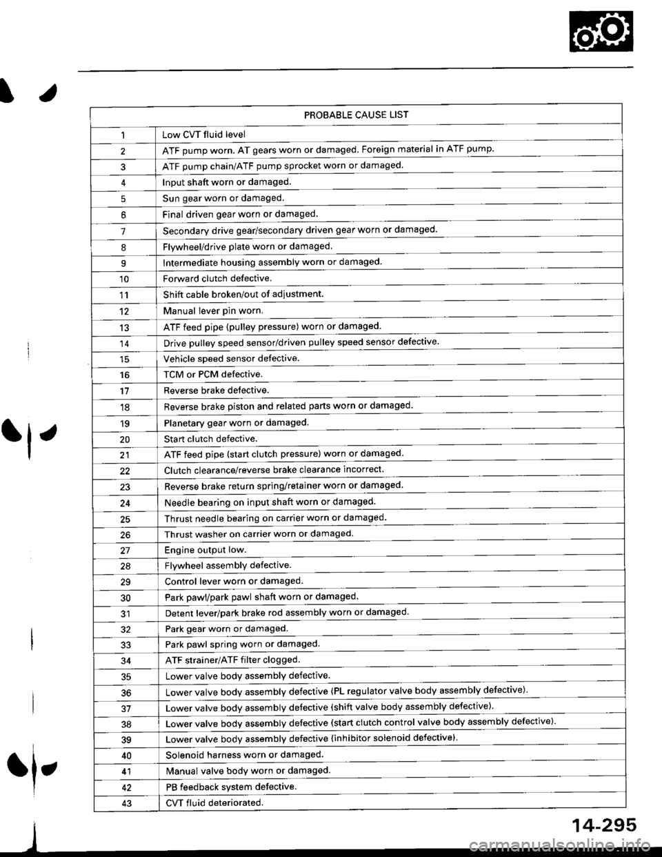
PROBABLE CAUSE LIST
Low CVT fluid level
ATF pump worn. AT gears worn or damaged. Foreign material in ATF pump.
ATF pump chain/ATF pump sprocket worn or damaged.
Input shaft worn or damaged.
Sun gear worn or damaged.
Final driven oear worn or damaqed,
Secondary drive gear/secondary driven gear worn or damaged-
5
6
1
8Flywheel/drive plate worn or damaged.
Intermediate housing assembly worn or damaged.9
'10Forward clutch defective.
Shift cable broken/out of adiustment.
M"nu"t t"uffi
ATF feed pipe (pulley pressure) worn or damaged.
Vchiclc speed sensor defective.
TCM or PCM defective.
Reverse brake detective.
1'�r
't2
13
14
16
'11
'18
1qPlanetary gear worn or damaged.
Sta rt clutch defective.
ATF feed pipe (start clutch pressure) worn or damaged
20
t't
Clutch clearance/reverse brake clearance incorrect.
23Reverse brake return spring/retainer worn or damaged
24Needle bearing on input shaft worn or damaged.
25Thrust needle bearing on carrier worn or damaged.
Thrust washer on carrier worn or damaged.
Enoine outout low.------------------------
Flvwhcel assemblv defective.
Control lever worn or damaged.
Park pawl/park pawl shaft worn or damaged
Detent lever/park brake rod assembly worn or damaged
27
29
30
32Park gear worn or damaged.
Park pawl spring worn or damaged.
ATF strainer/ATF filter clogged.
Lower valve body assembly defective.
Lower valve bodv assemblv defective (PL regulator valve body assembly defective)'
33
34
50
Lower valve bodv assembly defective (shift valve body assembly defective).
Lower valve bodv assemblv defective (start clutch control valve body assembly defective)'
39Lower valve bodv assemblv defective {inhibitor solenoid defective}
40Solenoid harness worn or damaged.
Manual valve body worn or damaged.
PB feedback system defective.
CVT fluid deteriorated.
41
43
14-295
Page 988 of 2189
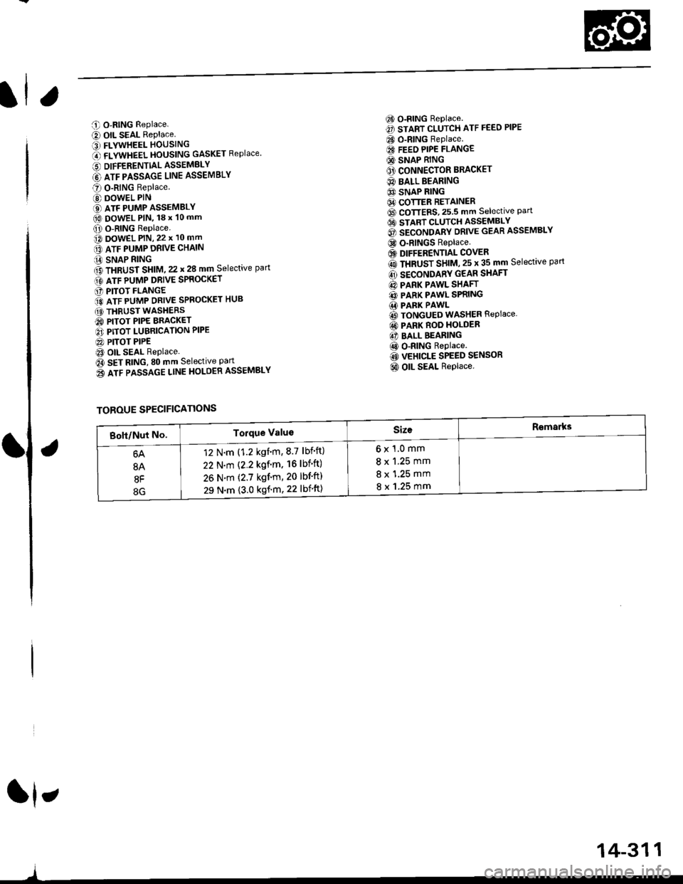
C O-RING Replace.
e) OIL SEAL RePlace.' FLYWHEEL HOUSING
O flVWneel }|OUSttttG GASKET Replace
6 DIFFERENTTALASSEMELY
@ lrr plsslce uruE ASSEMBLY
O O-RING Replace
@ DOWEL PIN
€) ATF PUMP ASSEMBLY(O DowEL PlN, 18 x 10 mm
O O-RING Replace.o DowEL PlN, 22 x 10 mm
lrr puup oRve cxltttt
iA SNAP RING
f3 fxaUst St|t|l, zz t 28 mm Selective part
Gt lrr punp ontve spaocxer
O PITOT FLANGE
ito nTF purrap ontve SPRoGKET HUB
(O THRUST WASHERS
@ PITOT PIPE BRACKET
O PITOT LUBRICATION PIPE
@ PITOT PIPEt3 OIL SEAL Replace.
Oa SEt AtitC, SO mm Selective Part
o3 lrr passlce ltnE HoLOER ASSEMBLY
6) o-RING Replace.
€) START CLUTCH ATF FEED PIPE
CO O-RING Replace.
€I FEEO PIPE FLANGE
@ SNAP RING
O' CONNECTOR BRACKET
@ BALL BEARING
6} SNAP RING64 COTTER RETAINER6D CoTTERS,25.5 mm selective Part6t stlnt cLutcH asseMsLv
@ secoruomv ontvE GEAR ASSEMBLY
@ o-RINGS Replace
6) DIFFERENTIAL COVER
rO ttaUSr SntU, zs t 35 mm Selective part
@ SECONDARY GEAR SHAFT
@ PARK PAWL SHAFT
@ PARK PAWL SPRING.1i PARK PAWL
@ TONGUED WASHER REPIACE,
@ PARK ROO HOLDER
@ BALL BEARING
@ o-RING Replace.
@ VEHICLE SPEED SENSOR
@ OIL SEAL Replace.
ft,
)
TOROUE SPECIFICATIONS
6x1.0mm
8 x 1.25 mm
8 x 1.25 mm
8 x 1.25 mm
12 N.m (1.2 kgnm,8.7 lbf'ft)
22 N.m (2.2 kgf'm. 16lbf'ft)
26 N.m (2.7 kgf'm, 20 lbf'ft)
29 N.m {3.0 kgf'm, 22 lbift)
14-311
Page 1005 of 2189
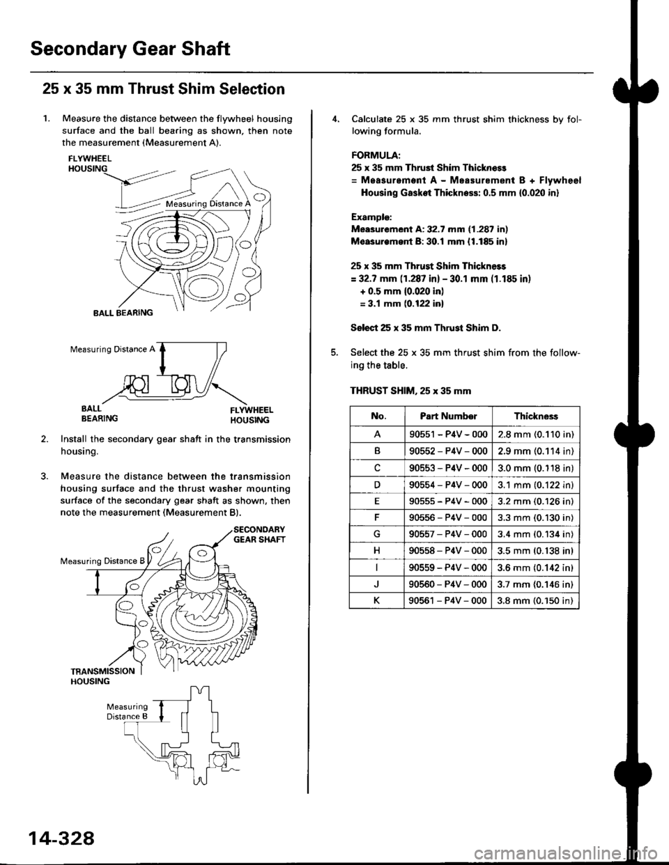
Secondary Gear Shaft
25 x 35 mm Thrust Shim Selection
1. Measure the distance between the flywheel housing
surface and the ball bearing as shown, then note
the measurement (Measurement A).
FLYWHEELHOUSING
>dt?'
BALL BEARING
EALL FLYWHEELBEARING HOUSTNG
Install the secondary gear shatt in the transmission
housing.
Measure the distance between the transmission
housing surface and the thrust washer mounting
surface of the secondary gear shaft as shown, then
note the measurement (Measurement B).
O
Measuring Distance A
BALL
14-328
Calculate 25 x 35 mm thrust shim thickness bv fol-
lowing formula.
FORMULA;
25 x 35 mm Thrust Shim Thicknoss
= Measurement A - Measurement B + Flywheel
Housing Gasket Thickness: 0.5 mm {0.020 in}
Example:
Measurement A: 32.7 mm (1.287 in)
Moasurem.nt B: 30.! mm {1.185 in}
25 x 35 mm Thrust Shim Thickness
= 32.7 mm (1.287 in) - 30.1 mm (1.185 in)
+ 0.5 mm {0.020 in)
= 3.1 mm (0.122 inl
Select 25 x 35 mm Thrust Shim D.
Select the 25 x 35 mm thrust shim from the follow-
ing the table.
THRUST SHIM, 25 x 35 mm
No.Part NumberThickne3s
90551 - P4V - 0002.8 mm (0.110 in)
B90552-P4V-0002.9 mm (0.114 in)
c90553-P4V-0003.0 mm (0.118 in)
D90554-P4V-0003.1 mm (0.122 in)
E90555-P4V-0003.2 mm (0.126 in)
90556-P4V-0003.3 mm (0.130 in)
G90557-P4V-0003.4 mm (0.134 in)
H90558-P4V-0003.5 mm (0.138 in)
90559-P4V-0003.6 mm {0.142 in)
90560-P4V-0003.7 mm (0.146 in)
K90561 - P4V - 0003.8 mm (0.'150 in)