Page 1174 of 2189
Front Brake Caliper
Reassembly (cont'dl
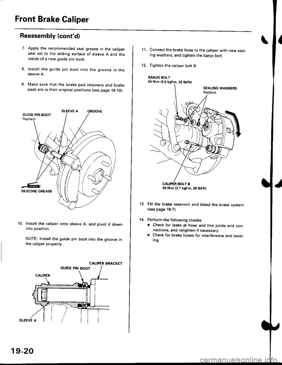
7.Apply the recommended seal grease in the caliperseal set to the sliding surface of sleeve A and theinside of a new guide pin boot.
Install the guide pin boot into the groove in thesleeve A.
Make sure that the brake pad retainers and brakepads are in their original positions (see page 19-10).
Install the caliper onto sleeve A, and pivot it downinto position.
NOTE: Install the guide pin boot into the groove inthe caliper properly.
BRACKET
SLEEVE A
19-20
11.Connect the brake hose to the caliper with new seal-ing washers, and tighten the banjo bolt.
Tighten the caliper bolt B.
Fill the brake reservoir and bleed the brake svstem(see page 19-7).
Perform the following checks.. Check for leaks at hose and line ioints and con-nectaons, and retighten if necessary.. Check for brake hoses for interference and twist-Ing.
13.
14.
BANJO BOLT
26 N.m (2.7 kgl.m, 20 lbtftl
Page 1188 of 2189
Rear Brake Caliper
Reassembly (cont'dl
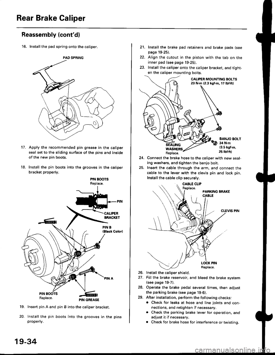
'16. Installthe pad spring onto the caliper.
Apply the recommended pin groase in the caliper
seal set to the sliding surface of the pins and inside
of the new pin boots.
Install the pin boots into the grooves in the caliper
bracket properly.
PIN BOOTSReplsce.
(Bl.ck Colorl
PINRepl6ce.
19. Insert pin A and pin B into the caliper bracket.
20. Install the pin boots into the grooves in thepropefly.
PAD SPRING
11.
PIN GREASE
19-34
pr ns
22.
21. Install the brake pad retainers and brake pads (see
page 19-25).
Align the cutout in the piston with the tab on the
inner pad (see page 19-25).
Install the caliper onto the caliper bracket. and tight-
en the caliper mounting bolts.
CALIPER MOUNTING BOLTS23 N.m {2.3 kg{.m. 17 lbf.ft)
WASHERSReplace.
BANJO BOLT34 N.m13.5 kg{.m.25 rbtft)
24.Connect the brake hose to the caliper with new seal,
ing washers, and tighten the banjo bolt,
Insert ths cable through the arm, and connect the
cabls to the lever with the clevis pin and lock pin.
Install the cable clip securely.
CLEVIS PIN
-t
//t
LOCK PINRoplace.
26. Install the caliDer shield.
27. Fill the brake reservoir, and bleed the brake svstem(see page 19-71.
28. Operate the brake pedal several times, then adjust
the parking brake (see page 19-6).
29. After installation, perform the following checks:. Check for leaks at hose and line joints and con-nections, and retighten if necessary.. Check the parking brake lever for operation, and
adjust it if necessary.
. Check for brake hose for interference or twistinq.
Page 1193 of 2189
Brake Hoses/Lines
LJ
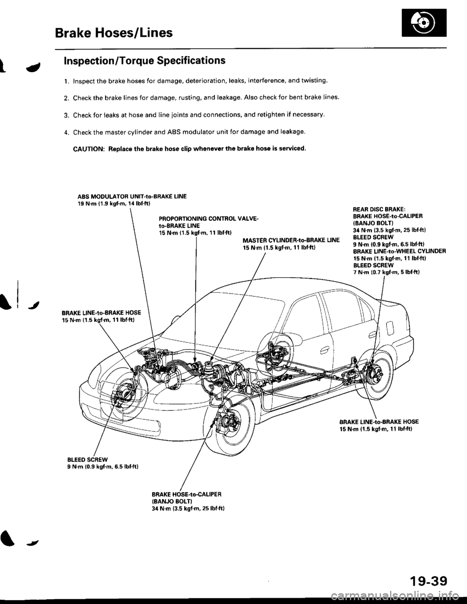
Inspection/Torque Specifications
t. Inspect the brake hoses for damage, deterioration, leaks, interference, and twisting.
2. Check the brake lines for damage, rusting. and leakage. Also check for bent brake lines.
3. Check for ieaks at hose and line ioints and connections, and retighten if necessary'
4. Check the master cylinder and ABS modulator unit for damage and leakage
CAUTION: Replace tho brake hose clip whenev€r the brake hose is serviced.
ABS MODULATOR UNIT-Io-BRAKE l-lNE19 N.m (1.9 kgf.m, 14lbl.ftl
PROPOBTIONING CONTROL VALVE.io-BRAKE LINEl5 N.m (1.511 tbf.ftl
MASTER CYLINDER-Io-BMKE LINE
15 N.m (1.5 ksrf.m, 11 lbf'ft)
REAR DISG BRAKE:BRAKE HOSE-to4ALlPER
{BANJO BOLT}34 N.m (3.5 kgtm,25 lbf ftlBLEEO SCREW9 N'm (0.9 kgf.m, 6.5 lM.ftlBRAKE LINE-to-WHEEL CYLINDER15 N.m (1.5 kgl.m, 11 lbf.ftlBLEED SCREW7 N.m {0.7 kst m, 5 lbf,ttl
JBRAKE LINE-io-aRAKE HOSE15 N.m {1.511 tbtft)
BRAKE LINE-Io-BRAKE HOSE15 N.m (1.5 kgt.m, 11 lbf'ft)
(BANJO BOLT}3,1 N.m 13.5 kgf.m, 25 lbf.ft)
J
19-39
Page 1194 of 2189
Brake Hoses/Lines
Hose Replacement
CAUTION:
. Bgfore reagsembling, chgck that all parts are free of
dust and othor foroign particles.
. Repl8ce parts with new ones whenever specified to
do so,
. Do not spill brake fluid on th6 vehicle; it may damage
tho paint; if brake fluid does contact the paint, wash
it off immediately with water.
1.Replace the brake hose if the hose is twisted, cracked,
or if it leaks.
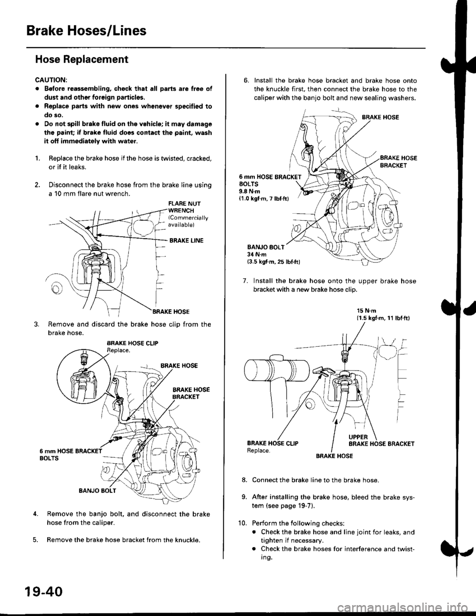
Disconnect the brake hose from the brake line using
a 10 mm flare nut wrench.
FLARE NUTWRENCHlCommerciallyava ilable)
BRAKE LINE
BRAKE HOSE
Remove and discard the brake hose cliD from the
brake hose.
Remove the banjo bolt, and disconnect the brake
hose from the caliper.
Remove the brake hose bracket from the knuckle.
19-40
10.
6. Install the brake hose bracket and brake hose onto
the knuckle first. then connect the brake hose to the
caliper with the banjo bolt and new sealing washers.
BRAKE HOSE
6 mm HOSE BRACKETBOLTS9.8 N.m{1.0 kgf m, 7 lbtfr}
BANJO BOI.T34 N.m{3.5 kgf.m,25 lbt.ftl
7. Install the brake hose onto the uooer brake hose
bracket with a new brake hose clip
15 N.m(1.s ks{.m, 11 lbl.ftl
Connect the brake line to the brake hose.
After installing the brake hose, bleed the brake sys-
tem (see page 19-7).
Perform the following checks:
. Check the brake hose and line joint for leaks, and
tighten if necessary.
. Check the brake hoses for interference and twist-
I ng.
8.
Page 1827 of 2189
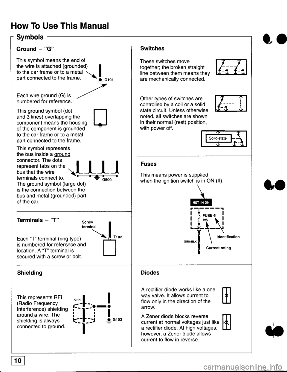
How To Use This Manual
Symbols
Ground - "G"
This symbol means the end ol
the wire is attached (grounded) Ito the car frame or to a metal I
part connected to the frame. \i oro,|
-t'
Each wire ground (G) it --/
numbered for reference.
oo
Switches
These switches move
together; the broken straight
line between them means the,
are mechanically connected.
Other types of switches are
controlled by a coil or a solid
state circuit. Unless otherwise
noted. all switches are shown
in their normal (rest) position,
with power off.
This ground symbol (dot
and 3 lines) overlapping the
component means the housing
of the component is grounded
to the car frame or to a metal
part connected to the frame.
This symbol represents
the bus inside a ground
connector. The dots I
i:l*,':1,'^:*,:"
;"
r"L I I I
terminals connect to.
The ground symbol (large dot)
is the connection between the
bus and metal (grounded) part
of the car.
Terminals - "T"
ffi
ffi
Solid-state
Fuses
This means power is supplied
when the ignition switch is in ON (ll).
Current rating
Diodes
A rectifier diode works like a one
way valve. lt allows current to
llow only in the direction of the
arrow.
A Zener diode blocks reverse
current at normal voltages just like
a rectifier diode. At high voltages.
however, a Zener diode allows
current to f low in reverse
oo
Each "T" lerminal (ring type)
is numbered for reference and
location. A "T" terminal is
secured with a screw or bolt.
Shielding
This represents RFI
(Radio Frequency
Interference) shielding
around a wire. The
shielding is always
connected to ground.
f--l;j-i",..
I
,,,,
T