1998 HONDA CIVIC dash bulb
[x] Cancel search: dash bulbPage 1713 of 2189
)
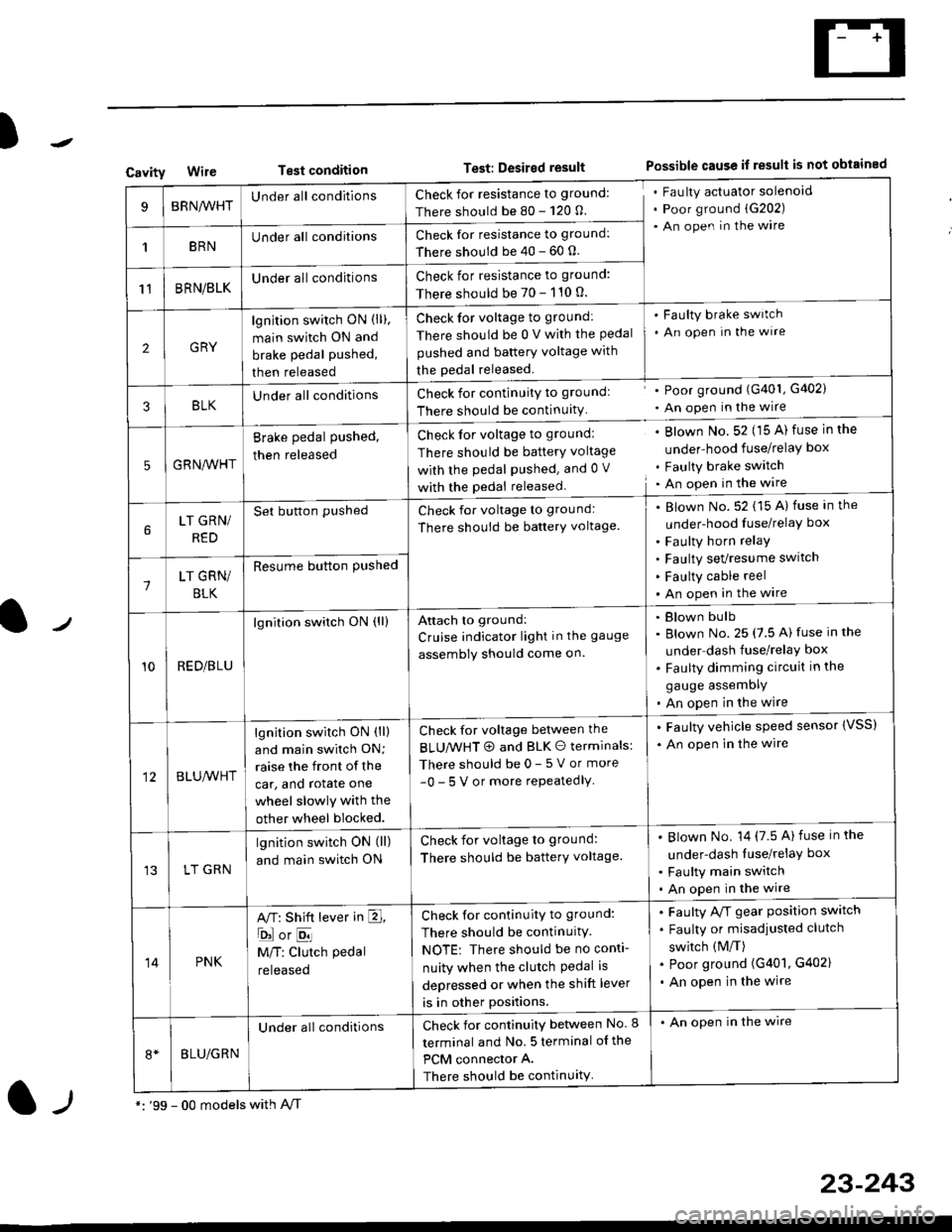
CavityWireTest conditionTest: Desired resultPossible cause if result is not obtained
BRNA/VHTUnder all conditionsCheck for resistance to ground:
There should be 80 - 120 O.
Fau lty actuator solenoid
Poor ground (G202)
An open in the wire
1BRNUnder all conditionsCheck for resistance to ground:
There should be 40 - 60 0.
11BRN/BLKUnder all conditionsCheck for resistance to ground:
There should be 70 - 110 0.
2GRY
lgn jtion switch ON (ll),
main switch ON and
brake pedal pushed,
then released
Check for voltage to ground:
There should be 0 V with the Pedal
pushed and battery voltage with
the pedal released.
'Faulty brake switch
. An open In the wlre
3BLKU nderall conditionsCheck for continuitY to groundl
There should be continuity
' Poor ground (G401, G402)
. An open in the wire
5GRNA,A/HT
Brake pedal pushed,
then released
Check for voltage to groundl
There should be batterY voltage
with the Pedal Pushed. and 0 V
with the pedal released
. Blown No. 52 (15 A) fuse in the
under-hood fuse/relaY box
. Faulty brake switch. An open in the wire
LT GRN/
RED
Set button pushedCheck for voltage to ground:
There should be batterY voltage.
Blown No. 52 (15 A) fuse in the
under-hood fuse/relaY box
Faulty horn relay
Faulty sevresume switch
Faulty cable reel
An open in the wire7LT GRN/
BLK
Resume button Pushed
10RED/BLU
lgnition switch ON (ll)Attach to ground:
Cruise indicator light in the gauge
assembly should come on.
Blown bulb
Blown No. 25 (7.5 A) fuse in the
under dash fuse/relay box
Faulty dimming circuit in the
gauge assemDly
An open in the wire
BLU,A/VHT
lgnition switch ON (ll)
and main swilch ON;
raise the front of the
car, and rotate one
wheel slowly with the
other wheel blocked.
Check for voltage between the
BLUMHT @ and BLK O terminals:
There should be 0- 5 V or more
-0- 5 V or more repeatedlY
. Faulty vehicle speed sensor {VSS)
. An open in the wire
LT GRN
lgnition switch ON (ll)
and main switch ON
Check for voltage to ground:
There should be batterY voltage.
Blown No. 14 (7.5 A)fuse in the
under-dash luse/relaY box
Faulty main switch
An open in the wire
14PNK
A,T: Shift lever in E,
ojorE
M/T: Clutch pedal
released
Check for continuity to ground:
There should be continuity.
NOTE: There should be no conti-
nuity when the clutch Pedal is
depressed or when the shift lever
is in other positions.
Faulty A/f gear position switch
Faulty or misadjusted clutch
switch (M/T)
Poor ground (G401, G402)
An open in the wire
BLU/GRN
Under all conditionsCheck for continuity between No. I
terminal and No. 5 terminal of the
PCM connector A.
There should be continuity
. An open in the wire
*: '99 - 00 models with A,/Tl-,
23-243
Page 1714 of 2189
Cruise Gontrol
3.
1.
2.
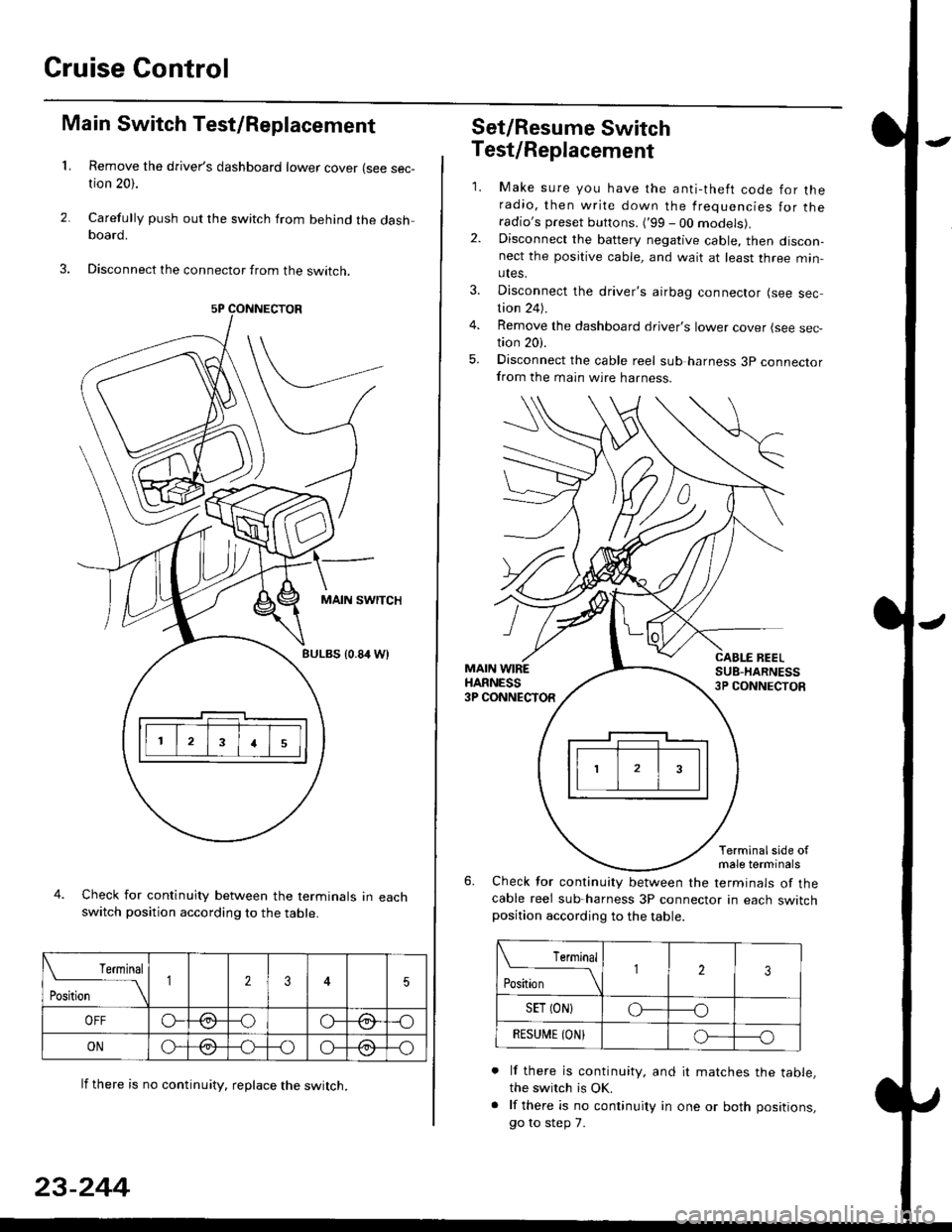
Main Switch Test/Replacement
Remove the driver's dashboard lower cover (see sec-tion 20).
Carefully push out the switch from behind the dashboard.
Disconnect the connector from the swtrcn.
MAIN SWITCH
BULBS {0.84 Wt
Check for continuity between the terminals in eachswitch position according to the table.
lf there is no continuity. reDlace the switch.
4.
Terminal
r**
--\235
OFFo--oGa\-o\:./\a/
ONo-/a-oo--o\:/\:/
23-244
Set/Resume Switch
5.
Test/Replacement
2.
1.
MAIN WIREHARNESS3P CONNECTOR
Make sure you have the anti-theft code for theradio, then write down the frequencies for theradio's preset buttons. ('99 - 00 models).Disconnect the battery negative cable, then discon-nect the positive cable, and wait at least three min-utes.
Disconnect the driver's airbag connector (see sec-tion 24).
Remove the dashboard driver's lower cover (see sec,tion 20).
Disconnect the cable reel sub harness 3p connectorfrom the main wire harness.
CABLE BEELSUB-HARNESS3P CONNECTOS
Terminalside ofmale terminals
Check for continuity between the terminals of thecable reel sub-harness 3P connector in each switchposition according to the table.
L Terminal
Position123
SET (ON}o----o
BESUi,|E IONIo-----o
lf there is continuity, and it matches the table,the switch is OK.
lf there is no continuity in one or both positions,
go to step 7.
Page 1733 of 2189
)
l-l
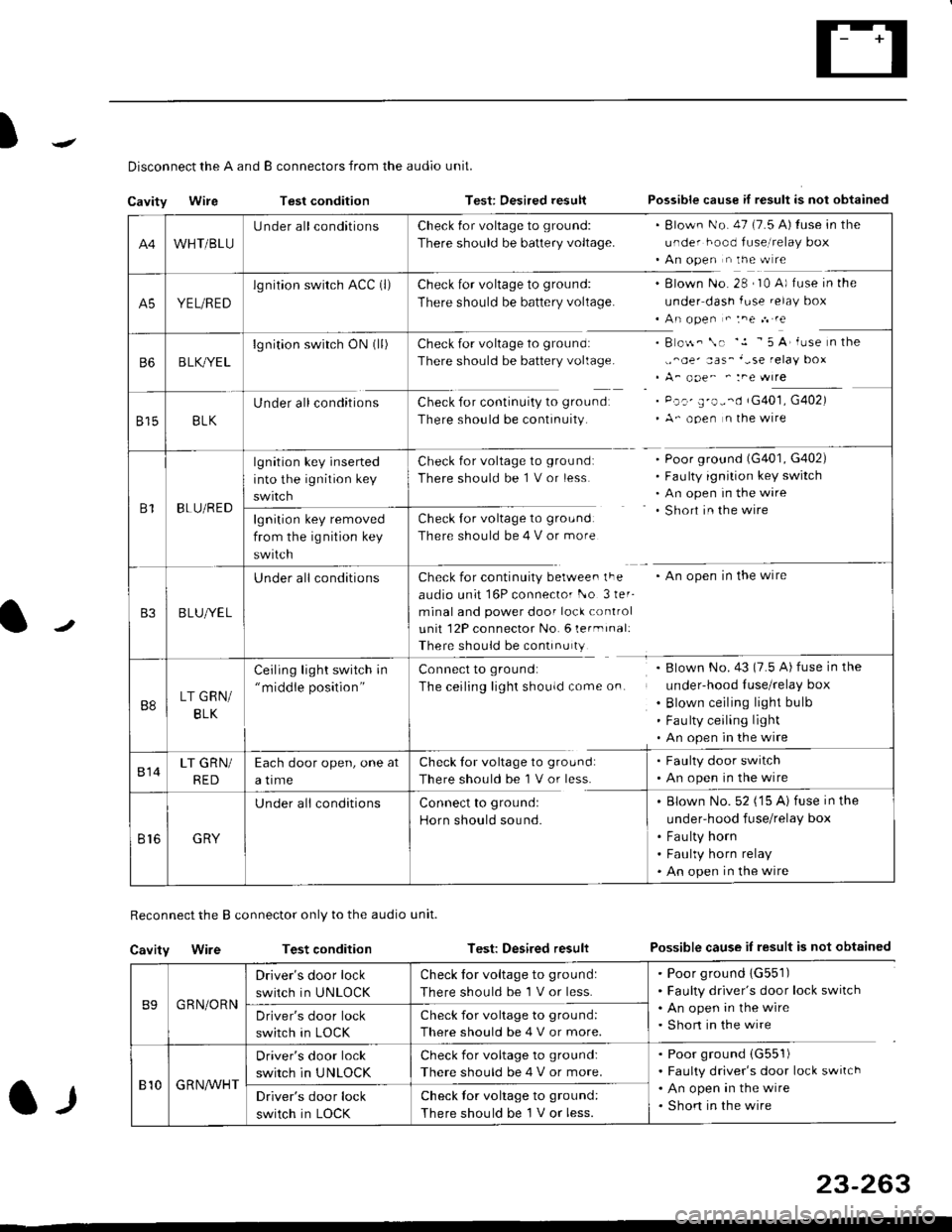
Disconnect the A and B connectors from the audio unit.
Cavity WireTest conditionTest: Desired resultPossible cause if result is not obtained
Reconnect the B connector only to the audio unit.
Cavity WireTest conditionTest: Desired resultPossible cause iI result is not obtained
B9GRN/ORN
Driver's door lock
switch in UNLOCK
Check for voltage to ground:
There should be 1 V or less.
. Poor ground 1G551). Faulty driver's door lock switch. An open in the wire. Short in the wireDriver's door lock
switch in LOCK
Check for voltage to grou nd:
There should be 4 V or more.
810G R NAr'r'HT
Driver's door lock
switch in UNLOCK
Check for voltage to ground:
There should be 4 V or more.
. Poor ground (G551)
. Faulty driver's door lock switch. An open in the wire. Shon in the wireDriver's door lock
switch in LOCK
Check lor voltage to ground:
There should be I V or less.
23-263
A4WHT/BLU
LJnder all conditionsCheck {or voltage to ground:
There should be battery voltage.
. Blown No. 47 (7.5 A) tuse in the
under hood fuse,i relay box. An open n the w re
A5YEL/RED
lg nition swirch ACC (l)Check for voltage to ground:
There should be battery voltage.
Blown No. 28 , I0 A) f use in the
under dash fuse.elay box
An open " :ne n re
Check for voltage to ground:
There should be battery voltage.
Check for continuity to groundr
There should be continuity.
B o$. \. '.1 - 5 A' iuse n the
,,^oe' aas_'-se relay box
A_ ooe^ ' :ne wrre
Pc.' E'o--d rG401, G402)
A- ooen n lhe wire
B6B LK,/YE L
lgnition switch ON0l)
8158LK
Under all conditions
B1BLU/RED
lgnition key inserted
into the ignition key
swrtch
Check for voltage to ground:
There should be 1 V or less
Check for voltage to ground:
There should be 4 V or more
Poor ground (G401, G402)
Faulty ignition key switch
An open in the wire
Short in the wire
An open in the wireCheck for continuity berwee. lFe
audio unit 16P connector l-o 3ler-
minal and power door lock control
unit 12P connector No. 6 lermrnal:
There should be continu ty
lgnition key removed
from the ig nition key
swtlcn
B3B LUlt/E L
U nderall conditions
B8LT GRN/
BLK
Ceiling light switch in"middle position"
Connect to ground:
The ceiling lighr shouldcome on.
Blown No.43 (7.5 A) fuse in the
under-hood Iuse/relay box
Blown ceiling light bulb
Fau lty ceiling light
An open in the wire
814LT GRN/
RED
Each door open, one at
a time
Check tor voltage to ground:
There should be'l V or less.
. Faulty door switch. An open in the wire
Br6GRY
U nderall conditionsConnect to groundl
Horn should sound.
. Blown No. 52 ('15 A) fuse in the
under-hood fuse/relay box
. Fau lty horn. Faulty horn relay. An open in the wire
Page 1764 of 2189
Troubleshooting
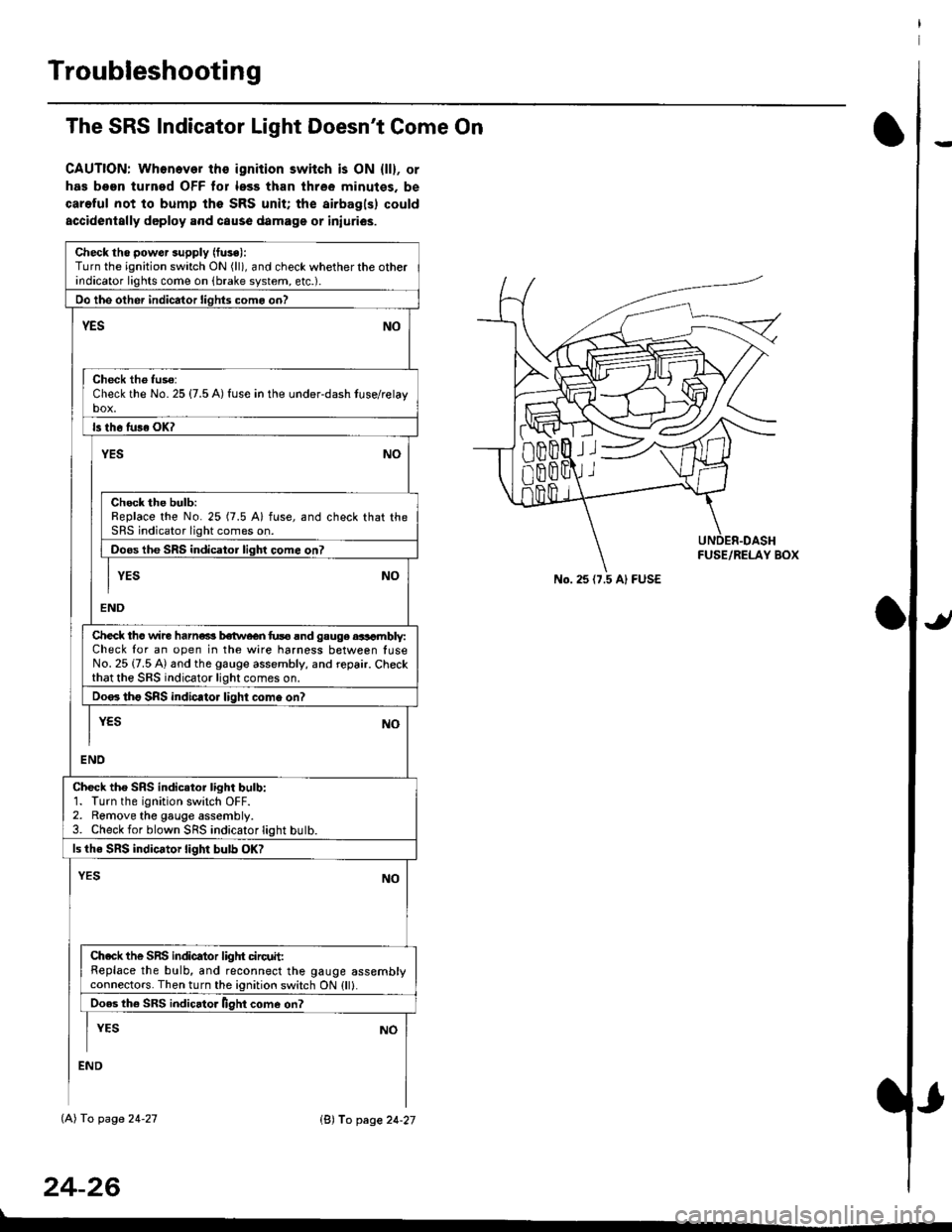
The SRS Indicator Light Doesn't Come On
CAUTION: Whonever ths ignition switch is ON {ll}, or
has been turned OFF tor less than three minutes. be
careful not to bump the SRS unit; the airbagls) could
accidentally deploy .nd caus6 damage or iniuri€s.
Check tho pow€r supply (fuse):
Turn the ignition switch ON (ll), and check whether the otherindicator lights come on (brake system, etc.).
Oo the other indicator liohts como on?
YESNO
Check th6 fuso:Check the No. 25 {7.5 A) fuse in the under-dash tuse/relayb"t
ls th6 tu36 OK?
NOYES
Check the bulb:Replace the No. 25 (7.5 A) fuse, and check that theSRS indicator light comes on.
Doos the SRS indicator liqhl come on7
I YES No
END
Check tho wire harns b€twecn fus6 and gauge aasambly:Check for an open in the wire harness between luseNo. 25 {7.5 A) and the gauge assembly, and repair. Checkthat the SRS indicator light comes on.
Doo. tho SRS indic.tor light como on?
I yEs No
I
END
Check tho SRS indicator light bulb:1. Turn the ignition switch OFF.2. Remove the gauge assembly.3. Check for blown SRS indicator light butb.
ls the SRS indicator light bulb OK?
NOYES
Ch.ck the SnS indicator liglrt circuit:Replace the bulb, and reconnect the gauge assemblyconnectors. Then turn the ignition switch ON {ll}.
Ooes th6 SRS indicato. llght come on?
I YEs No
:ND
lAl To page 24-27
24-26
lB'J fo page 24-27
))
No. 25 (7.5 Al FUSE
Page 1968 of 2189
- '99-'00 Models
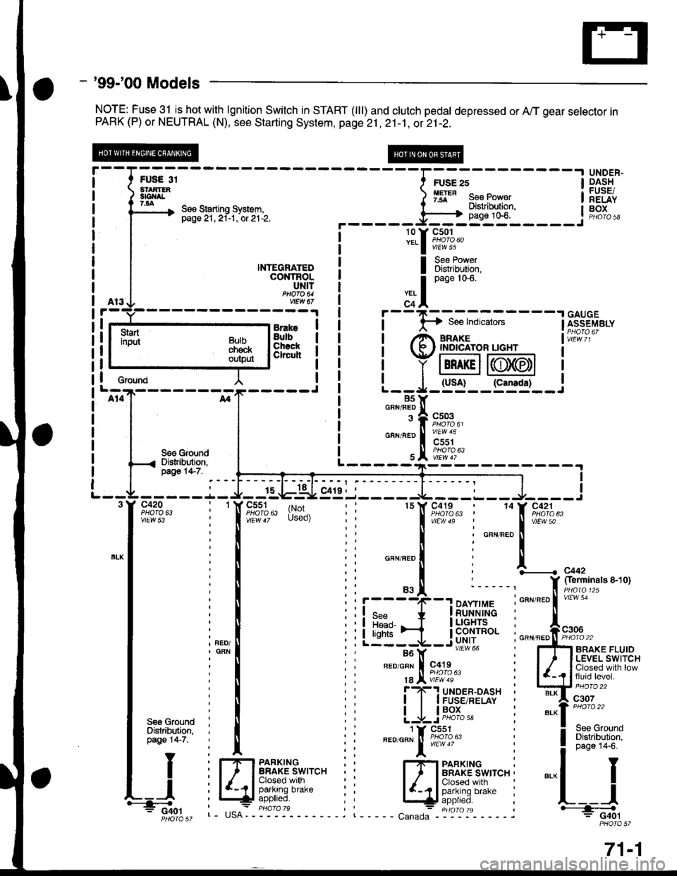
NOTE: Fuse 31 isJtot with lgnition Switch in START (lll) and clutch pedal depressed or A,,/T gear selector inPARK (P) or NEUTRAL (N), see Starting System, page 21 ,2i-1, ot 21-2.
UNDER"DASHFUSEiRELAYBOX
I
I
I
I
I erouna
BrakeBulbChsckCheuh
NTEGNATEDcot{TRoLUNITftoa 64vEw a7
I Bi?[lT':i,
S€6 GroundDistribution,pago 14-7.I
I
c420PHO|O 6ivtEw 53
c551PHOfA 63c419PHO|O 63 |(r;'Used)
1514
r----4(--.1 DAYnMEI q* * |RUNN|NG
Llt:i-ib'f#Iu'"'' i---Y -- """* i
FED/GFN I c419 :
18 Jl iE?'8' :f ?-'! uloen-oasx 'I I I FUSE/RELAY
| | lP9l_- :
1 Y Cs51".o'o"" ! iffl1oru"
l:
I Sss GfoundI Distribution.I pag€ 147.
TY
tt
L_l.'-4o.'
Fr,lrs 3i
--Iil;--------l
3m" ) 9ff" s"" po*"r I
\, See Starting system. I "- . Distribution. l- pasezr.zi-t.'or'ztlz. ._____=Fl}_*t0"_____.1
l3.f ftT:4""
Bulbchekoutp$
L----------
,.. I
o"n" tot'
c+l
i
- -
F-; ffi ;-
- - -
I [i;"s"'"."I rt^ amre I vir:i i,
t (R ' rNprcAroR uGHr I
i Y lBn rcll6T6tl I
| | (usA! (canrda) |L--*-:J- -:--'�-- J85Y85Yo""'"T|
"";%u,
"""'"';i"a#;",
\e#1k"
I
f,............ c44,
f $?'#"ot'to'-*'1;;
GBN/FED II PHOIO 22
5fi ennxe rluroI ' I LEVEL SWITCH
| /_,? lfJ",ii"."gl'.-
w::::"
"'-1":::::-.
! 3:"'lll"*l
".-l I
L__l+: G40lPHOIO 57
l-rlrl PARKTNGI ' I BRAKE SWITCH ,
lIdft"f[]r'"r'" i
c"n"o":- "igt-ol'- - - - - j
71-1
Page 2028 of 2189
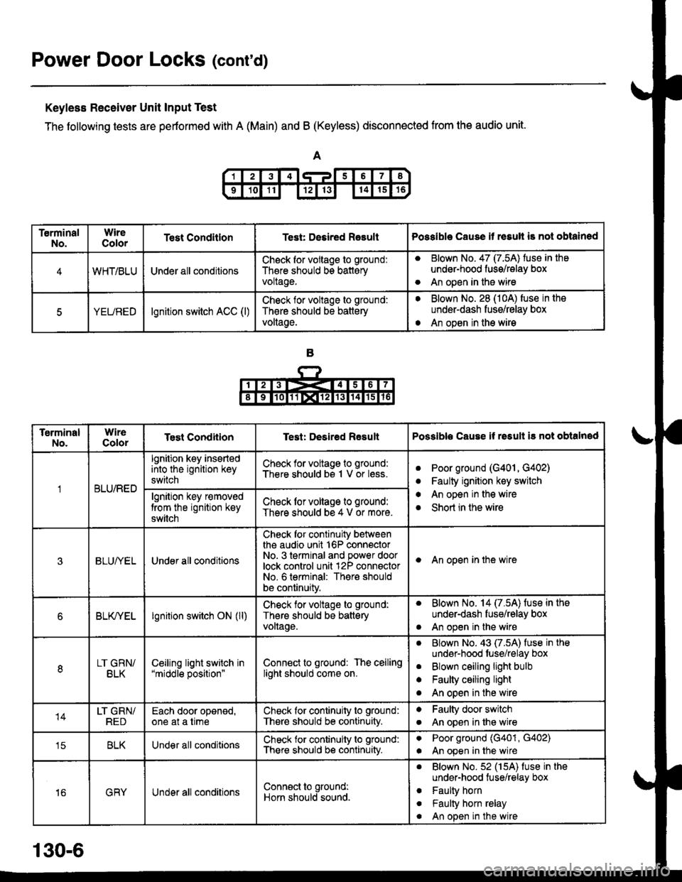
Power Door Locks (cont'd)
Keyless Receiver Unit Input Test
The following tests are pertormed with A (Main) and B (Keyless) disconnected from the audio unit.
TerminalNo.WireColorTest ConditlonTest: Desired RasultPossible Cause it resull is not obtained
4WHT/BLUUnder all conditionsCheck for vollage to ground:
There should bs batteryvoltage.
aBlown No. 47 (7.5A) tuse in the
under-hood fuss/relay box
An open in the wireo
5YEUREDlgnition switch ACC (l)Check lor voltage to ground:
Th€re should be battery
voltage.
aBlown No. 28 (10A) fuse in the
underdash fusg/relay box
An open in the wirea
TerminalNo.WireColorTest CondiiionTest: Desired ResultPossible Cause if rssult i3 not obtalned
BLU/RED
lgnition key insertedinto the ignition key
switch
Check for voltage to ground:
There should bs 1 V or less.aPoor ground (G401, G402)
Faulty ignition key switch
An open in the wire
Short in the wire
a
a
algnition key r€moved
trom the ignition key
switch
Check lor voltage to ground:
There should be 4 V or more.
3BLUI/ELUnder all conditions
Check for continuity betweenthe audio unit 16P connectorNo- 3 terminal and power doorlock control unit 12P connsctorNo. 6 terminal: There should
be continuity.
I An open in the wire
6BLK/YELlgnition switch ON (ll)Check for voltage to ground:
Thers should be batteryvollage.
. Blown No. 14 (7.5A) fuse in the
under-dash fuse/relay box
. An open in the wire
8LT GRN/BLKCeiljng light switch in"middle position"Connect to ground: The ceilinglight should come on.
aBlown No. 43 (7.5A) fuse in the
undsr-hood fuse/relay box
Blown ceiling light bulb
Faulty ceiling light
An open in the wire
a
a
o
14LT GRN/REDEach door oponed,one at a timeCheck for continuity to ground:
There should be continuity.
aFaulty door switch
An open in lhe wirea
tcBLKUnder all conditionsCheck for continuity to ground:
There should b€ continuity.
aPoor ground (G401, G402)
An open in the wirea
16GRYUnder all conditionsConn€ct to ground:
Horn should sound.
. Blown No.52 (15A) fuse in the
under-hood tuse/relay box
. Faulty horn
. Faulty horn relay
. An open in the wire
130-6
Page 2038 of 2189
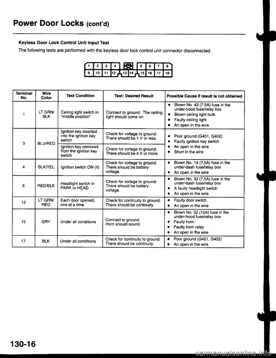
Power Door Locks (cont'd)
Keyless Door Lock Control Unit Input Test
The following tests are performed with the keyless door lock control unit connector disconnected.
TerminalNo.WireColorTest ConditionTest: Desir€d ResultPossible Cause if result ls not obtain€d
1LT GRN/BLKCeiling light switch in"middle position"Connect to ground: The ceilinglight should come on.
aBlown No. 43 (7.5A) luse in theunder-hood tuse/relay box
Blown ceiling light bulb
Faulty ceiling light
An open in the wire
o
a
a
3BLU/RED
lgnition key insertedinto the ignition keyswitch
Ch€ck lor voltage to ground:There should be I V or less.aPoor ground (G401, G402)
Faulty ignition key switch
An open in the wire
Short in the wire
a
a
o
lgnition key removedlrom the ignition keyswitch
Check for voltage to ground:There should be 4 V or more.
BLfiEtlgnition switch ON (ll)Check lor voltage to ground:
There should be batteryvoltage.
. Blown No. 14 (7.54) fuse in theunder-dash fuse/relay box
. An open in the wire
bREO/BLKHeadlight switch inPARK OT HEAD
Check for voltage to ground:
There should be batteryvoltage.
aBlown No. 32 (7.5A) luse in theunder-dash fuse/relay box
A faulty headlight switch
An open in the wire
a
o
LT GRN/RED
Each door opened,one at a timeCheck lor continuity to ground:
There should be continuitv.
oFaulty door switch
An open in the wireo
15GRYUnder all conditionsConnect to ground:
Horn should sound.
. Blown No. 52 (154) fuse in theunder-hood fuse/relay box
. Faulty horn
. Faulty horn relay
o An open in the wire
BLKUnder all conditionsCheck lor continuity to ground:
There should be continuity.
aPoor ground (G401 , G402)
An open in the wirea
130-16
Page 2131 of 2189
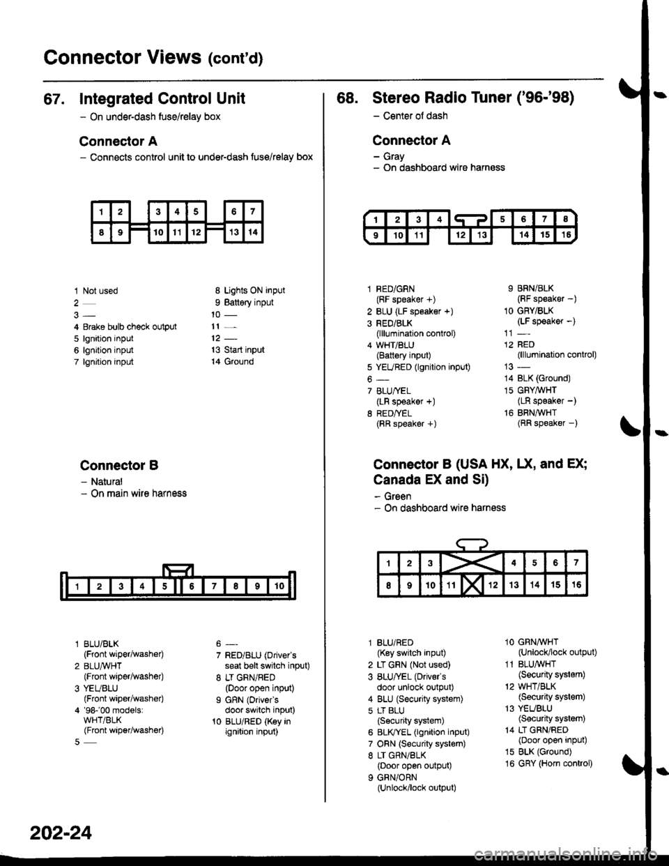
Gonnector Views (cont'd)
67. Integrated Control Unit
- On underdash fuse/relay box
Connector A
- Connects control unit to under-dash fuse/relay box
1 Not used
4 Erake bulb check output
5 lgnition input
6 lgnition input
7 lgnjtion input
Connectol B
- Natural- On main wire harness
l BLU/BLK
{Front wiper/washer)
2 BLUA/VHT(Front wiper/washe0
3 YEUBLU(Front wiper/washer)
4 '98-'00 models:WHT/BLK(Front wiper/washer)
8 Lights ON input
9 Battery input
11 _
13 Start input
14 Ground
7 RED/BLU (Driver's
seat b€lt switch input)
8 LT GRN/RED(Door open input)
I GRN (Oriver's
door switch input)'t0 BLU/RED (Key inignition input)
202-24
68. Stereo Radio Tuner ('96-'98)
- Center ot dash
Connector A
- Gray- On dashboard wire harness
1 RED/GRN(RF speaker +)
2 BLU (LF speaker +)
3 RED/BLK(lllumination control)
4 WHT/BLU(Battery input)
5 YEURED (lgnition input)
6-
7 BLU/YEL(LR speaker +)
8 RED/TEL(RR speaker +)
9 BRN/BLK(RF speaker -)
1O GRY/BLK(LF speaker -)
12 RED(lllumination control)
14 BLK (Ground)
15 GFY,4/VHT(LR speaker -)
16 BRNAVHT(RR speaker -)
Connector B (USA HX, UX, and EX;
Canada EX and Si)
- Green- On dashboard wire harness
l BLU/RED(Key switch input)
2 LT GRN (Not used)
3 BLU/'EL (Drivels
door unlock output)
4 BLU (Security system)
5 LT BLU
{Security system)
6 BLIVYEL (lgnition input)
7 ORN (Security system)
8 LT GRN/BLK(Door open output)
9 GRN/ORN(Unlock/lock output)
1O GRNAVHT(Unlock/lock output)
1 1 BLU/WHT(Security system)
'2 WHT/BLK(Security system)
13 YEUBLU(Security system)
14 LT GRN/RED(Door open input)
15 BLK (Ground)
16 GRY (Horn conkol)