1998 HONDA CIVIC buttons
[x] Cancel search: buttonsPage 1669 of 2189
Switch Test
lMake sure you have the anti-theft code for the
radio, then write down the frequencies for the
radio's preset buttons ('99 - 00 models).
Disconnect the battery negative cable, then disconnect
the positive cable, and wait at least three minutes.
Disconnect the driver's airbag connector (see sec-
tion 24).
Remove the driver's dashboard lower cover (see
section 20).
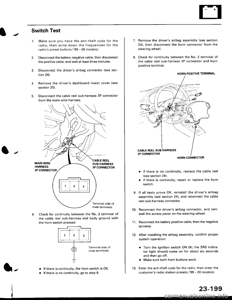
Disconnect the cable reel sub-harness 3P connector
from the main wire harness.
2.
3.
4.
5.
1.
MAIN WIREHARNESS3P CONNECTOR
SUB-HABNESS3P CONNECTOR
REEL
6.
Terminalside olmale terminals
Check for continuity between the No. 2 terminal of
the cable reel sub-harness and body ground with
the horn switch pressed.
alf there is continuity, the horn switch is OK.
lf there is no continuity, go to step 6l-
-\
1.
8.
10.
'I 1.
9.
Remove the driver's airbag assembly (see section
24), then disconnect the horn connector from the
steering wheel.
Check for continuity between the No. 2 terminal of
the cable reel sub-harness 3P connector and horn
positive terminal.
lf there is no continuity, replace the cable reel
(see section 24).
lf there is continuity, repair or replace the horn
swtlcn,
lf all tests prove OK, reinstall the driver's airbag
assembly (see section 24), and reconnect the cable
reel sub-harness connector.
Reconnect the driver's airbag connector, and rein-
stall the access panel on the steering wheel.
Reconnect the battery positive cable, then the negative
termtnar.
After installing the airbag assembly, confirm proper
system operation:
12.
Turn the ignition switch ON (ll); the SRS indica-
tor light should come on for about six seconds
and then go off.
Make sure both horn buttons work.
13. Enter the anti-theft code for the radio, then enter the
customer's radio station presets ('99 - 00 models).
HORN CONNECTOR
23-199
Page 1714 of 2189
Cruise Gontrol
3.
1.
2.
Main Switch Test/Replacement
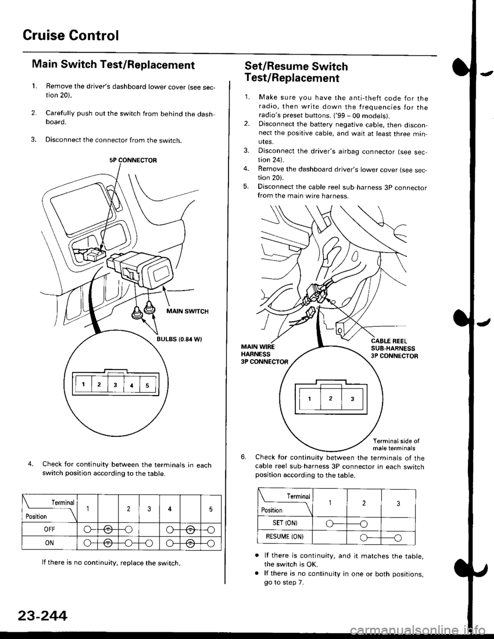
Remove the driver's dashboard lower cover (see sec-tion 20).
Carefully push out the switch from behind the dashboard.
Disconnect the connector from the swtrcn.
MAIN SWITCH
BULBS {0.84 Wt
Check for continuity between the terminals in eachswitch position according to the table.
lf there is no continuity. reDlace the switch.
4.
Terminal
r**
--\235
OFFo--oGa\-o\:./\a/
ONo-/a-oo--o\:/\:/
23-244
Set/Resume Switch
5.
Test/Replacement
2.
1.
MAIN WIREHARNESS3P CONNECTOR
Make sure you have the anti-theft code for theradio, then write down the frequencies for theradio's preset buttons. ('99 - 00 models).Disconnect the battery negative cable, then discon-nect the positive cable, and wait at least three min-utes.
Disconnect the driver's airbag connector (see sec-tion 24).
Remove the dashboard driver's lower cover (see sec,tion 20).
Disconnect the cable reel sub harness 3p connectorfrom the main wire harness.
CABLE BEELSUB-HARNESS3P CONNECTOS
Terminalside ofmale terminals
Check for continuity between the terminals of thecable reel sub-harness 3P connector in each switchposition according to the table.
L Terminal
Position123
SET (ON}o----o
BESUi,|E IONIo-----o
lf there is continuity, and it matches the table,the switch is OK.
lf there is no continuity in one or both positions,
go to step 7.
Page 1721 of 2189
Power Door Locks
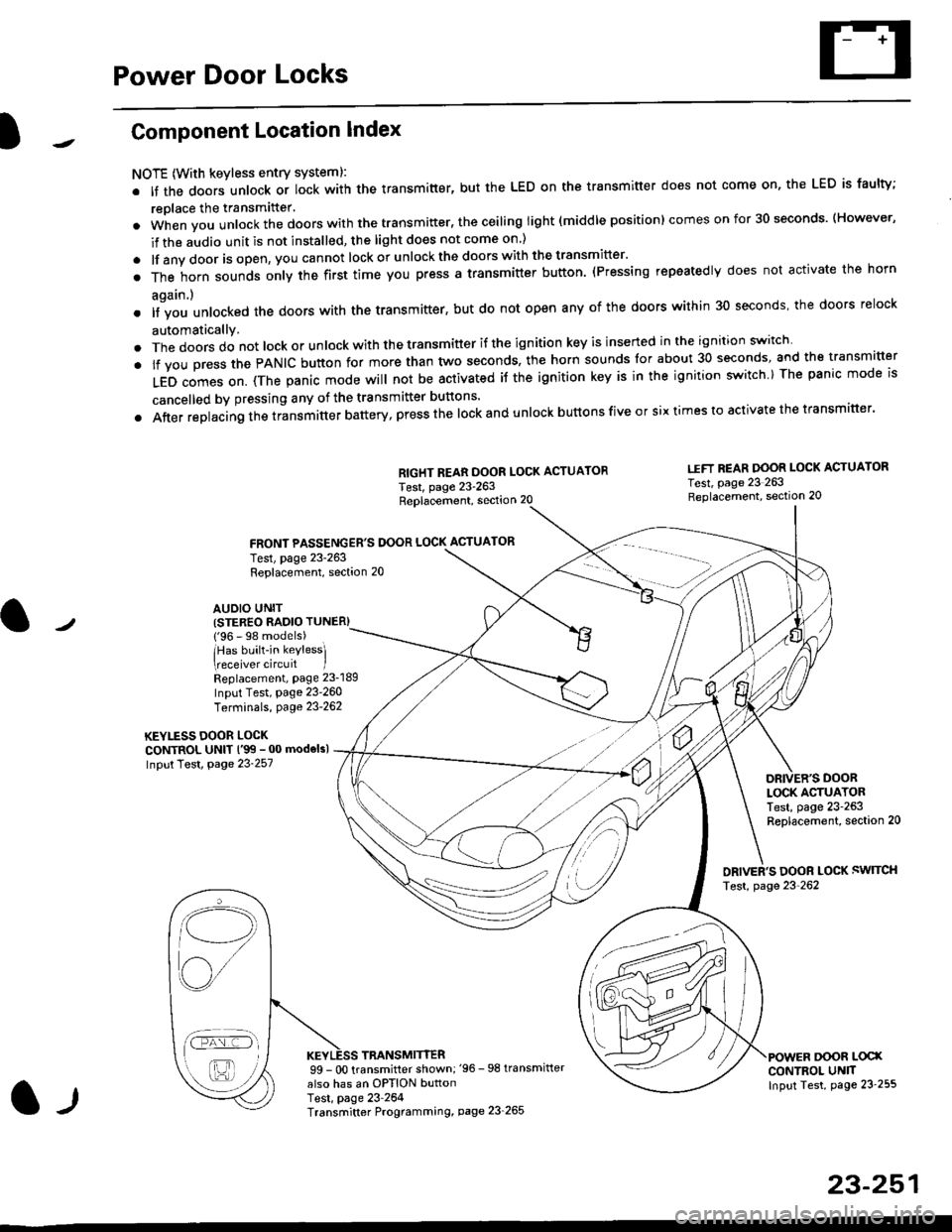
Component Location Index
NOTE (With keyless entry systeml:
. It the doors unlock or lock with the transmitter, but the LED on the transmitter does not come on, the LED is faulty;
replace the transmitter'
. when vou unlock the doors with the transmitter, the ceiling light (middle position) comes on for 30 seconds. (However,
if the audio unit is not installed, the light does not come on )
. lf any door is open, you cannot lock or unlockthe doors with the transmitter'
. The horn sounds only the first time you press a transmitter button. (Pressing repeatedly does not activate the horn
again.)
o lf vou unlocked the doors with the transmitter, but do not open any of the doors within 30 seconds, the doors relock
automatically.
. The doors do not lock or unlock with the transmitter if the ignition key is inserted in the ignition switch
. lf you press the PANIC button for more than two seconds, the horn sounds for about 30 seconds, and the transm'fer
LED comes on. (The panic mode will not be activated iJ the ignition key is in the ignition switch ) The panic mode is
cancelled by pressing any of the transmitter buttons'
o After replacing the transmitter battery, press the lock and unlock buttons five or six times to activate the transmitter'
Replacement, section 20
FRONT PASSENGER'S DOOR LOCK ACTUATOR
RIGHT REAR DOOR LOCK ACTUATOR
Test, page 23-263
I.IFT REAR DOOR LOCK ACTUATOR
Test, page 23 263Replacement, section 20
LOCK ACTUATORTest, page 23-263Replacement, section 20
ORIVER'S DOOR LOCK SWITCH
Test, page 23'262
DOOR L@XCONTROL UN]TInput Test, page 23 255
23-251
Test, page 23-263Replacement, section 20
AUDIO UNIT(STER€O RADIO TUNER)
{'96 - 98 models)
lHas built-in keylessl
eceiver circuit IReplacement, page 23-189
Input Test, page 23-260
Terminals, page 23-262
KEYLESS DOOR LOCKCONTROL UNIT l'99 - 00 modelsl
Input Test, Page 23-257
l-l
TRANSMITTER99 - 0O transmitter shown;'96 -98 transmifter
also has an OPTION buttonTest, page 23-264Transmitter Programming, page 23_265
Qi,,a/
/----
L(ru
i'.-8,-'l
/'-'6
Page 1737 of 2189
)
Transmitter Programming ('96 - 98 models)
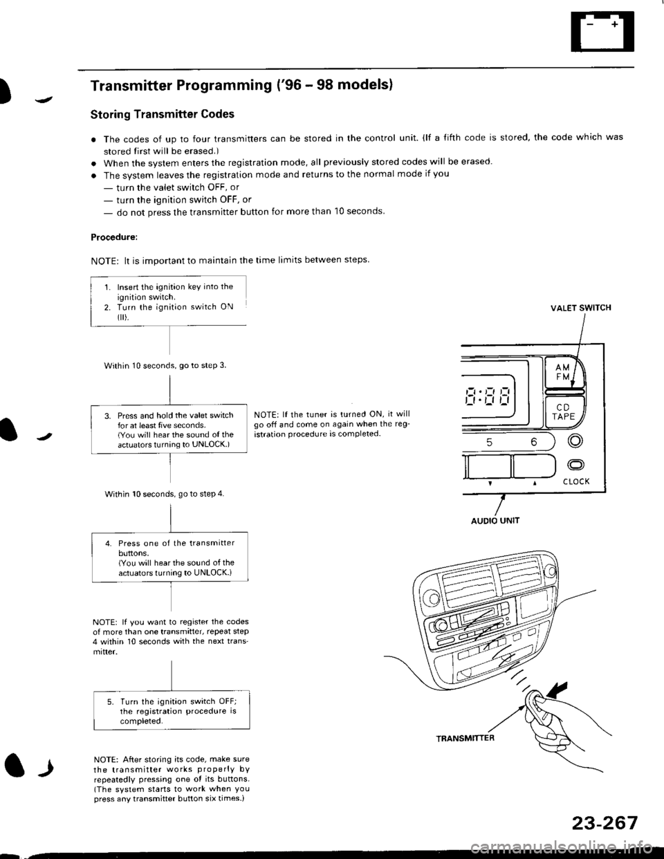
Storing Transmitter Codes
. The codes of up to four transmitters can be stored in the control unit. {lf a {ifth code is stored, the code which was
stored tirst will be erased.)
. When the system enters the registration mode, all previously slored codes will be erased.
. The system leaves the registration mode and returns to the normal mode if you
- turn the valet swirch OFF, or
- turn the ignition switch OFF, or
- do not press the transmitter button for more than 10 seconds
Procedure:
NOTE: lt is important to maintain the time limits between steps
VALET SWITCH
NOTE: lf the tuner is turned ON, it willgo off and come on again when the reg-
istration procedure is completed-
l-l
NOTE: lf you want to register the codesof more than one transmitter, repeat step4 within 10 seconds with the next trans'mitter.
NOTE: After storing its code, make sure
the transmitter works properly bYrepeatedly pressing one ot its buttons.(The system starts to work when Youpress any transmitter button six times-)
TRANSMTITTER
23-267
--
Insert the ignition key into the
ignition swatch.Turn the ignit;on switch ON
flr).
Within 10 seconds, go to steP 3.
3. Press and hold the valet switchfor at least tive seconds.(You will hear the sound of theactuators turnang to UNLOCK.)
Within 10 seconds. go to step 4.
4. Press one of the transmitterbuttons,(You will hear the sound of theactuators turning to UNLOCK.i
AUDIO UNIT
Page 1738 of 2189
Power Door Locks
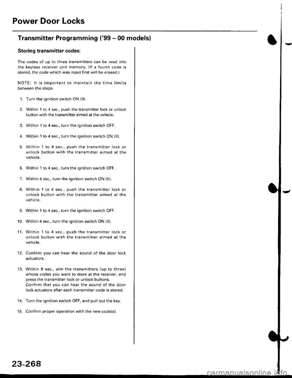
Transmitter Programming ('99 - 00 modelsl
Storing transmitter codes;
The codes of up to three transmitters can be read into
the keyless receiver unit memory. (lf a fourth code is
stored, the code which was input first will be erased.)
NOTE: lt is important to maintain the time limits
between the steps.
'1. Turn the ignition switch ON (ll).
2. Within 1 to 4 sec., push the transmitter lock or unlock
button with the transmitter aimed at the vehicle.
3. Within I to 4 sec., turn the ignition switch OFF.
4. Within 1 to 4 sec., turn the ignition switch ON 1ll).
5. Within 1 to 4 sec., push the transmitter lock or
unlock button with the transmitter aimed at the
vehicle.
6. Within 1 to 4 sec., turn the ignition switch OFF.
7. Within 4 sec., turn the ignition switch ON (ll).
8. Within 1 to 4 sec., push the transmitter lock or
unlock button with the transmitter aimed at the
vehicle.
9.Within 1 to 4 sec., turn the ignition switch OFF.
Within 4 sec., turn the ignition switch ON (ll).
Within '1 to 4 sec., push the transmitter lock or
unlock button with the transmitter aimed at the
vehicle.
Confirm you can hear the sound of the door lock
acIuarors.
Within 8 sec., aim the transmitters (up to three)
whose codes you want to store at the receiver, and
press the transmitter lock or unlock buttons.
Contirm that you can hear the sound of the door
lock actuators after each transmitter code is stored.
Turn the ignition switch OFF, and pull out the key.
Confirm proper operation with the new code(s).
'10.
11.
12.
14.
23-268
Page 1807 of 2189
)
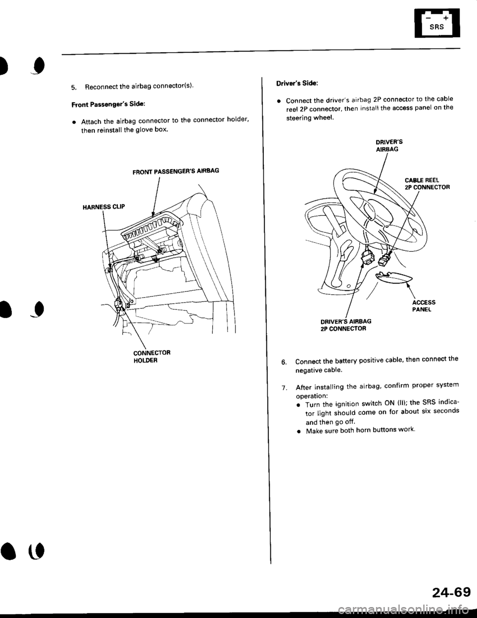
5, Reconnect the airbag connector(s)'
Front Passengor's Side:
a Attach the airbag connector to the connector holder'
then reinstallthe glove box.
FRONT PASSENGER'S AIRBAG
oo
24-69
Driver's Side:
a Connect the driver's airbag 2P connector to the cable
reel 2P connector, then install the acc€ss panel on the
steering wheel
DRIVER'S AIRBAG2P CONNECTOR
6. Connect the battery positive cable, then connect the
negative cable.
7. After installing the
operatlon:
. Turn the ignition
tor light should
and then go off
a Make sure both horn buttons work
airbag, confirm Proper sYstem
switch ON (ll); the SRS indica-
come on for about six seconds
Page 1813 of 2189
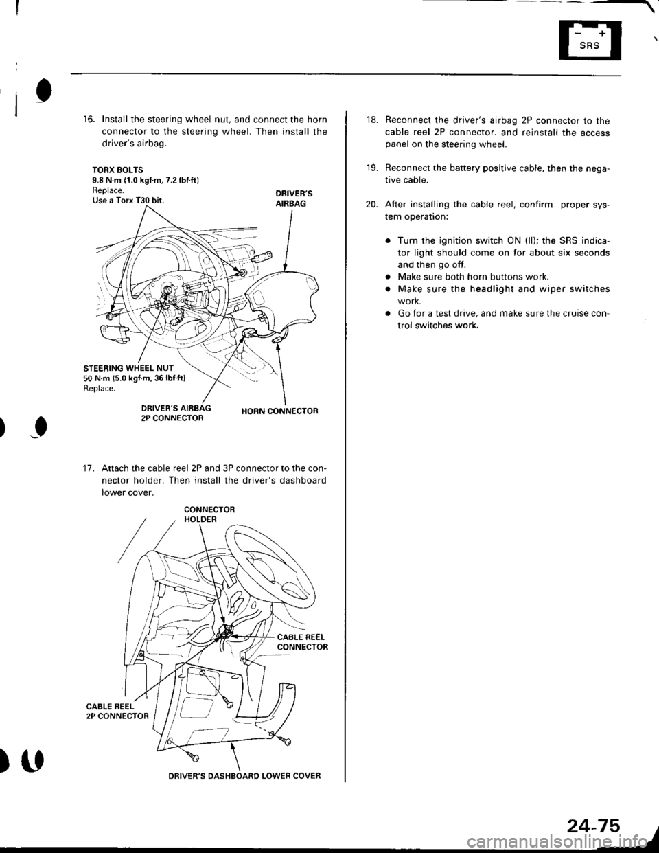
16. Install the steering wheel nut, and connect the horn
connector to the steering wheel. Then install the
driver's airbag.
TORX SOLTS9.8 N m 11.0 kgf m, 7.2 lbtftlReplace.Use a Torx T30 bit.
STEERING WHEEL NUT50 N.m 15.0 kgf.m,36lblft)Replace.
DRIVEB'SAIRBAG
DRIVER'S2P CONNECTOBHORN CONNECTOB
I
17.Attach the cable reel 2P and 3P connector to the con-
nector holder. Then install the driver's dashboard
lower cover.
)UDRIVER'S DASHBOARD LOWER COVER
24-75
18. Reconnect the driver's airbag 2P connector to the
cable reel 2P connector. and reinstall the accesspanel on the steering wheel.
19. Reconnect the battery positive cable, then the nega-
tive cable.
20. After installing the cable reel, confirm proper sys-
tem operation:
Turn the ignition switch ON (ll); the SRS indica-
tor light should come on for about six seconds
and then go off.
Make sure both horn buttons work.
Make sure the headlight and wiper switches
Go for a test drive, and make sure the cruise con
trol switches work.
a
a
Page 2026 of 2189
Power Door Locks (cont'd)
- How the Circuit Works
Keyless Entry System
The keyless door locks combine the power door
locks with a remote keyJob transmitter. The keyless
receiver unit is part of the radio. The keyless
receiver unit receives direct inputs f rom the ignition
key switch, the passenger door switches, and an
indirect input trom the driver's door switch through
the integrated control unit.
Power Door Locks (With or Wlthout Keyless)
The power door lock system is made up of the
oower door lock control unit. driver's door lock
switch, and individual door lock actuators. The
power door locks are controlled by the driver's door
lock switch and the driver's door lock actuator
switch.
Transmitter (With Keyless Entry)
The transmitter sends coded radio wave signals to
the keyless receiver unit when one ot its buttons is
pressed. Each transmitter has a unique code that
must be 'laught" to the keyless receiver unit before
it can operate the door locks or any other lunction.
Up to 4 transmitters can be programmed to operate
the keyless door locks.
Door Locking (With or without Keyless Entry)
When you push the driver's door lock switch to the
lock position, ground is applied to the GBN/IVHT
wire to the oower door lock control unit. The control
unit then applies battery voltage to the WHT/RED
wire and ground to the YEURED wire. The
passenger door lock actuators then activate to lock
the corresponding door locks.
When you lock the driver's door with the key or door
lock knob, it is mechanically locked, and the driver's
door lock actuator switch applies ground to the
oower door lock control unit. The control unit then
applies battery voltage to the WHT/RED wire and
ground to the YEURED wire, activating the
passenger door lock actuators which lock the doors.
Dool Locking with Transmitter
When you press the LOCK button on the remote
transmitter, the power door lock control unit applies
battery voltage to the WHT/RED wire and ground to
the YEURED wire. The passenger door lock
actuators then activate and lock the doors. A ground
slgnal is also applied to the BLU/RED wire to lock
the driver's door. lf any door is open, you cannot lock
it using the remote transmitter.
Door Unlocking (With or Without Keyless Entry)
When you push the driver's power door lock switch
to the unlock position, ground is applied to the
GRN/ORN wire to the power door lock control unit.
The control unit then applies battery voltage to the
YEURED and BLU/RED wires and ground to the
WHT/RED wire. The door lock actuators then
activate to unlock the doors.
When you unlock the driver's door with the key or
the door lock knob, it is mechanically unlocked; the
other doors do not unlock.
Door Unlocking (With Transmltter)
When you press the UNLOCK button on lhe remote
transmitter once. the power door lock control unit
applies battery voltage to the WHT/RED wire and
ground to the BLU/RED wire to unlock the driver's
door. When you press the UNLOCK button twice,
the control unit then applies ground to the YEURED
wires to activate the passenger door locks. lf you do
not open a door within 30 seconds after unlocking
the doors with the transmitter, the doors
automatically relock.
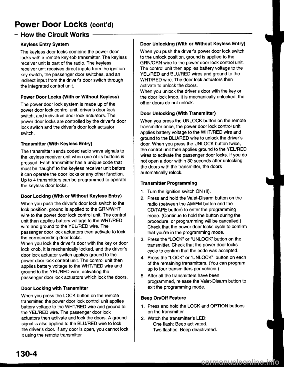
Transmltter Programming
1 . Turn the ignition switch ON (ll).
2. Press and hold the Valet-Disarm button on the
radio (between the AM/FM button and the
CD/TAPE button) to enter the programming
mode. (Continue to hold the button during the
procedure, or programming will be cancelled.)
Check that the power door locks cycle to confirm
that you're in the programming mode.
3. Press the "LOCK' or "UNLOCK' button on the
transmitter. Check that the power door locks
cycle to confirm that the code was accepted.
4. Press the "LOCK" or "UNLOCK" button on each
of the remaining transmitters. (You can program
up to four transmitters per vehicle.)
5. After all the transmitters have been
programmed, release lhe Valet-Disarm button to
exit the programming mode.
Beep On/Oft Feature
'I . Press and hold the LOCK and OPTION buttons
on the transmitter.
2. Watch the transmitter's LED:
One flash: Beeo activated.
Two tlashes: Beeo deactivated.
130-4