1998 HONDA CIVIC Wheels
[x] Cancel search: WheelsPage 559 of 2189

Emission Control System
Ch€ck the EVAP purge controlsolenoid valv6:1. Disconnect the 2P connectorfrom the EVAP purge controlsolenoid valve.2. Ouickly raise the engine speedto 3,000 rpm.
Insped vacuum hose routing.lf OK. roplace the EVAP purge
control solonoid valve.
Chock tor r short in the wir€
{PCS line):1. Turn the ignition switch OFF.2. Disconnect ECM/PCM connec-tor A (32P).
3- Check tor continuity betweenthe EVAP purge control sole-noid valve 2P connector termi-nal No. 2 and body ground.
Check the vacuum when hot:1. Turn the ignition switch OFF.2. Block the rear wheels and setthe parking brake.3. Jack up the lront of the vehi-cle and support it with safetystands.4. Start the engine. Hold theengine at 3,000 rpm with noload (in Park or neutrali until
the radiator fan comes on, thenlet it idle.5. Check for vacuum at the vac-uum hose with transmissionin gear (A/T in E position,
lvl/T in 1st gear) after startingthe engine.6. Ouickly raise the engine speedto 3,000 rpm.
Rooair shoft in the wire belwegnthe EVAP pulg6 control solenoidvalvs and tho ECM/PCM {A61.ls there continuity?
Substitute a known-good ECM/PCM and rech6ck. lt 3ymptom/indicrtion 90e3 rway, r6plac6 th€o.iginal ECM/FCM.
Check th€ EVAP purge controlsolenoid valve:1. Turn the;gnition switch OFF.2. Disconnect the 2P connectorfrom the EVAP purge controlsolenoid valve and warm itup to normal operating tem-perature again if necessary.3. Start the engine.4- At the harness side, measurevoltage between the EVAPpurge control solenoid valve2P connector terminal No. 1and No.2 with the transmis-sion in gear {A/T in E posi-tion, M/T in lst geari.
In3pect vacuum hoae routing.lf OK, repl.ce EVAP purge con-trol solonoid valve.ls there battery voltage?
Chock for an open in the wire(lG1 lina):At the harnoss side, measure volt-age beNveen the EVAP purge con-trol solenoid valve 2P connectorterminal No. 1 and body ground.
Repair open in the wire b€lwe€nEVAP purge contrl 3olenoid valv6and lhe No. 15 ALTERNATOR SPSENSOR 17.5 A, fu3e.
ls there battery voltage?
Evaporative Emission (EVAPI Controls (cont'dl
(From page 11-289)
(To page 11-291)
11-290
IJ
EVAP PURGE CONTROL SOLENOIDVALVE 2P CONNECTOR IC114I
PCS
IRED/YEL)
temaletermrnars
of
PCS(RED/YEL)
tGlIBLK/YEL)
{To page 11 291)
Page 628 of 2189

Transmission Assembly
l
,
{
Removal
@Make sure iacks and safoty stands are placad plop-
erly (3ee section l).
Apply parking braks and block rear wheels so car
will not roll off stands and fall on you while working
under il.
CAUTION: Us6 fonder cove6 to avoid damaging painted
sudaces.
Disconnect the negative (-) cable from the battery,
then the positive (+l cable.
Drain the transmission oil. then reinstall the drain
plug with a new washer (see page 13-47).
Remove the intake air duct and the air cleaner hous-
ing assembly (see s€ction 5).
Disconnect the back-up light switch connector and
the transmission ground wire.
Remove the lower radiator hose clamp from the
transmission hanger B.
L
8 x 1 .25 mm22Nm12.2kgl'm�,
LOWER RADIATORHOSE CLAMP
16 rbtft)
13-48
7.
Bemove the wire harness clamps.
Disconnect the starter motor cables and the vehicle
speed sensor (VSS) connector.
8 x 1.25 mm8.8 N.m (0.9 kgf.m,6.5 tbtftl
STARTERMOTORCABLES
8. Remove the clutch line bracket and the slav6 cylin-
oer.
NOTE: Do not operate the clutch pedal once the
slave cylinder has been removed.
\J
Page 682 of 2189

Description
(cont'dl
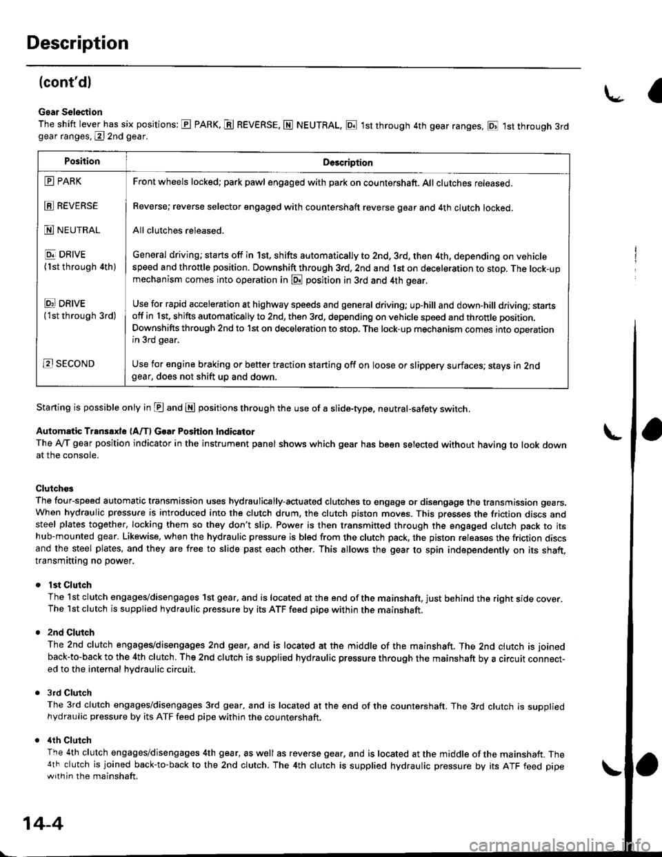
Gear Selection
The shift lever has six positions: E PARK. E REVERSE, N NEUTRAL, E 1st through 4th gear ranges, E 1st through 3rdgear ranges, @ 2nd gear.
Starting is possible only in E and E positions through the use of a slide-type, neutral-safety switch.
Automatic Transaxle (A/f, Gear Position Indicator
The Ay'T gear position indicator in the instrument panel shows which gear has been selected without having to look downat the console.
Clutch€s
The four-speed automatic transmission uses hydraulically-actuated clutches to engage or disengage the transmission gears.When hydraulic pressure is introduced into the clutch drum, the clutch piston moves. This presses the friction discs andsteel plates together, locking them so they don't slip. Power is then transmitted through the engaged clutch pack to itshub-mounted gear. Likewise, when the hydraulic pressure is bled from the clutch pack, the piston releases the friction discsand the steel plates, and they are free to slide past each other. This allows the gear to spin independently on its shaft,transmitting no power.
lst Clutch
The 1st clutch engages/disengages 1st gear, and is located at the end of the mainshaft, just behind the right sroe cover.The 1st clutch is supplied hydraulic pressure by its ATF feed pipe within the mainshaft.
2nd Clulch
The 2nd clutch engagegdisengages 2nd gear, and is located at the middle of the mainshaft. The 2nd clutch is joined
back-to-back to the 4th clutch. The 2nd clutch is supplied hydraulic pressure through the mainshaft by a circutr connect-ed to the internal hvdraulic circuit,
3rd Clutch
The 3rd clutch engages/disengages 3rd gear, and is located at the end of the countershaft. The 3rd clutch is suooliedhydraulic pressure by its ATF feed pipe within the countershaft.
ilth Clutch
The 4th clutch engages/disengages 4th gear, as well as reverse gear, and is located at the middle of the mainshaft. The4th clutch is joined back-to-back to the 2nd clutch. The 4th clutch is supplied hydraulic pressure by its ATF feed pipewith in the mainshaft.
\-a
PositionDe3cription
E PARK
E REVERSE
N NEUTRAL
E DRIVE
{1st through 4th)
Ei DRtvE('lst through 3rd)
B SECOND
Front wheels locked; park pawl engaged with pa* on countershaft. All clutches released.
Reverse; reverse selector engaged with countershaft reverse gear and 4th clutch locked.
All clutches released.
General driving; starts off in 1st, shifts automatically to 2nd, 3rd, then 4th, depending on vehiclespeed and throttle position. Downshift through 3rd, 2nd and 1st on deceleration to stop. The lock-upmechanism comes into operation in @ position in 3rd and 4th gear.
Use for rapid acceleration at highway speeds and general driving; up-hill and down,hill dfiving; stansotf in 1st, shifts automatically to 2nd, then 3rd, depending on vehicle speed and throttle position.
Downshifts through 2nd to lst on deceleration to stop. The lock-up mechanism comes into operationin 3rd gear,
Use for engine braking or better traction starting off on loose or slippery surfaces; stays in 2ndgear, does not shift up and down.
14-4
Page 683 of 2189

One-way Clulch
The one-way clutch is positioned between the countershaft 1st gear and the park gea., with the park gear splined to the counter-
shatt, The 1st gear provides the outer race surface, and the park gear provides the inner race surface. The one-way clutch
locks up when power is transmitted from the mainshaft 1st gear to thetountershaft 1st gear. The lst clutch and gears
remain engaged in the 1st, 2nd. 3rd, and 4th gear ranges in the p!1, p! or L?l position.
However, the one-way clutch disengages when the 2nd, 3rd, or 4th clutches/gears are applied in the E, E or @ position.
This is because the increased rotational speed of the gears on the countershaft overrides the locking "speed range" of the
one-way clutch. Thereafter, the one-way clutch free-wheels with the 1st clutch still engaged.
zNO CLUTCH ,lTH CLUTCH
1ST CLUTCH
MAINSHAFT
COUNTERSHAFT
ONE.WAY CLUTCH
INSIDE OF ONE.WAYCLUTCHSplaned with countershaft
disengage outsideand inside oI the
3RO CLUTCH
OUTSIDE OF ONE.WAYCLUTCH
PANK GEAR
The sprags engage/
OVER-RIDINGLOCKING SPEED CONDITIONLOCKING CONDITION
14-5
Page 789 of 2189

The following symptoms can be caused
by improper repair or assembly
Check these items,on th€^ ltems on thePROBABLE CAUSE DUE TO NOTES ListIMPROPER REPAIR List
Vehicle creeps in N position.R1, R2
Vehicle does not move in &l or Pll position.R4
Transmission locks up in E position.R3, R11
Excessive drag in transmission.R6K,R
Excessive vibration, rpm related.R7
Noise with wheels moving onlY.R5
Main seal pops out.R8
Various shifting problems.R9, RlO
PROBABLE CAUSE DUE TO IMPROPER REPAIR
lmproper clutch clearance.
lmproper gear clearance.
Park lever installed upside down.
one-way {sprag) clutch installed upside down.
Reverse selector hub installed upside down.
ATF pump binding.
Torque converter not fully seated in ATF pump.
Main seal improperly installed.
Springs improperly installed.
Valves improperly installed.
Shift fork bolt not installed.
14-11
Page 790 of 2189

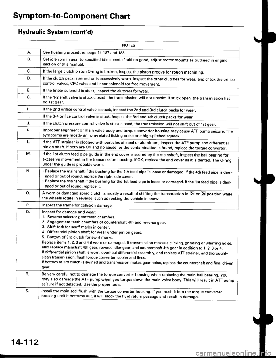
Symptom-to-Component Chart
Hydraulic System (cont'dl
G.
n,
set idle rpm in gear to specified idle speed. lf still no good, adjust motor mounts as outlined in enginesection of this manual.
lf the clutch pack is seized or is excessively worn. inspect the other clutches for wear, and check the orificecontrol valves, CPC valve and linear solenoid for free movement.
lf the linear solenoid is stuck, inspect the clutches for wear.
lmproper alignment or main valve body and torque converter housing may cause ATF pump seizure. Thesymptoms are mostly an rpm-related ticking noise or a high-pitched squeak.
lf the l st clutch feed pipe guide in the end cover is scored by the mainshaft, inspect the ball bearing forexcessive movement in the transmission housing. lf oK, replace the end cover as it is dented. The o-rinounder the guide is probably worn.
Replace the mainshaft if the bushing for the 4th feed pipe is loose or damaged. lf the 4th feed pipe is danFaged or out of round, replace the right side cover.
Replace the mainshaft if the bushing for the 1st feed pipe is loose or damaged. lf the 1st feed pipe is darn-aged or out of round, replace it.
A worn or damaged sprag clutch is mostly a result of shifting the transmission inthe wheels rotate in reverse, such as rocking the vehicle in snow.
or E position while
Inspect for damage and wear:
1. Reverse selector gear teeth chamfers.
2. Engagement teeth chamfers of countershaft 4th and reverse gear.
3. Shift fork for scuff marks in center.
4. Differential pinion shaft for wear u nder pin ion gears.
5. Bottom of 3rd clutch for swirl marks.
Replace items 1,2,3 and 4 if worn or damaged. lf transmission makes a clicking, grinding orwhirring noise,also replace mainshaft 4th gear, reverse idler gear. and countershaft 4th gear in addition to 1, 2, 3 or 4.lf differential pinion shaft is worn, overhaul differential assembly, and replace ATF strainer, and thoroughlyclean transmission, flush torque converter, cooler and lines.lf bottom of 3rd clutch is swirled and transmission makes gear noise, replace the countershaft and final drivengear.
Be very careful not to damage the torque converter housing when replacing the main ball bearing, you
may also damage the ATF pump when you torque down the main valve body. This will result in ATF pumpseizure if not detected. Use the oroper roors.
Install the main seal flush with the torque converter housing. lf you push it into the torque converterhousing until it bottoms out, it will block the fluid return passage and result in damage.
See flushing procedure, page 14-187 and 188.
lf the large clutch piston O-ring is broken, inspect the piston groove for rough machining.
lf the l-2 shift valve is stuck closed, the transmission will not upshift. lf stuck open, the transmission hasno 1st gear.
lf the znd orifice control valve is stuck. inspect the 2nd and 3rd clutch oacks for wear.
lf the 3-4 orifice control valve is stuck, inspect the 3rd and 4th clutch oacks for wear.
lf the clutch pressure control valve is stuck closed, the transmission will not shift out of 1st gear.
lf the ATF strainer is clogged with particles of steel or aluminum, inspect the ATF pump and differentialpinion shaft. lf both are OK and no cause for the contamination is found, replace the torque converter.
Inspect the frame for collision damage.
14-112
Page 791 of 2189

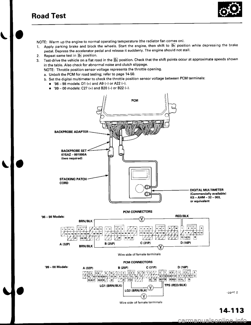
Road Test
NOTE: Warm up the engine to normal operating tem peratu re (the rad iator fan comes on )'
1. Apply parking brake and block the wheels. Start the engine, then shift to E position while depressing the brake
Dedal, Depress the accelerator pedal and release it suddenly. The engine should not stall'
2. Repeat same test in E Position.
3. Test-drive the vehicle on a flat road in the E position. Check that the shift points occur at approximate speeds shown
in the table. Also check for abnormal noise and clutch slippage.
NOTE: Throttle position sensor voltage represents the throttle opening
a. Unbolt the PCM for road testing; refer to page 14-50.
b. Setthedigital multimeter to check the th rottle position sensor voltage between PCM terminals;
. '96 - 98 models: D1 {+) and A9 (-) or 422 (-}.
. '99 - 00 models: C27 (+) andB20t-) orB22{-}.
BACKPROBE ADAPTER
BACKPROBE SET07sAz - 001oq)A{two requiredl
DIGIIAL MULTIMETERlCommercially available)KS-AHM-32-003,or equivalenl
'96 - 98 Modelsr
Wire side ol temale terminals
PCM CONNECTORS
B t25Pl c (31P)
LG1 IBRN/BLK)
I (25P1c (31P}
A t32PtD (16P)
Wire side ol female terminals
'9!t - 00 Models:
1+113
Page 794 of 2189

Stall Speed
Test
CAUTION:
. To prev€nt transmission damage, do not t6st stall speed for more than ro sgconds at a time.. Do not shift the levor while raising the engine speed.. Bo sule lo remove the pressure gauge betoro testing stall speed.
'1. Engage the parking brake, and block the front wheels.
2. Connect a tachometer to the engine, and start the engine.
3. Make sure the Ay'C switch is OFF.
4. After the engine has warmed up to normal operating temperature (the radiator fan comes on). shift into E position.
5. Fully depress the brake pedal and accelerator for 6 to g seconds, and note engine speed.
6. Allow two minutes for cooling, then repeat the test in @ and @ positions.
NOTE:
. Stall speed tests should be used for diagnostic purposes only,. Stall speed should be the same in o., E and E positions.
Stall Spsed RPM:
Specification: 2.700 rpm
Service Limit: 2,550 - 2,850 rDm
TROUBLEPROBABLE CAUSE
. Low fluid level or ATF pump outDur. Clogged ATF strainer. Pressure regulator valve sluck closeo. Slipping clutch
. Slippage of 4th ctutch
. Slippage of 2nd clutch
. Slippage of lst clut"tr or. t"t g""io*-*"y "lut"h
Stall rpm high in D., E and E positions
Stall rpm high in El position
Stall rpm high in E posirion
Stall rpm high in E position
Stall rpm low in LDa . El and E positrons. Engine output low. Torque converter one-way clutch slipping
14-116