Page 380 of 2189

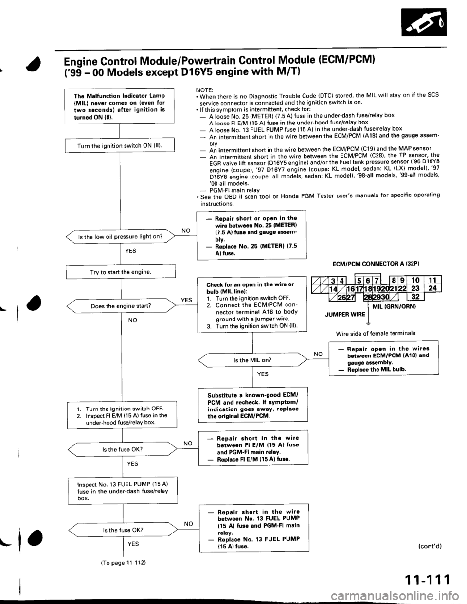
Engine Control Module/Powertrain Control Module (ECM/PCM)
('95 - 00 Models except Dl6Y5 engine with M/T)
NOTE:. When there is no Diagnostic Trouble Code lDTC) stored, the MIL will staY on if the SCS
seruice connector is connected and the ignition switch is on.. lf this symptom is intermittent, check for:- A loose No. 25 (METER) {7.5 A) fuse in the underdash fuse/relay box- A loose Fl E/M (15 Alluse in the undeFhood fuse/relay box- A loose No. 13 FUEL PUMPfuse (15 A) in the under-dash fuse/relay box- An intermittent shon in the wire between the ECM/PCM (A18) and the gauge assem'
- an intermittent short in the wire between the ECM/PCM (C19) and the MAP sensor- An intermittent short in the wire between the ECM/PCM {C28), the TP sensor, the
EGR valve lift sensor (D16Y5 engine) and/or the Fuel tank pressure sensor ('96 D16Y8
engine (coupe),'97 D16Y7 engine lcoupe: KL model, sodan: KL (LX) model)"g7
Dt6Y8 engine (coupe: all mod;ls, sedanl KL model),'98-all models,'99-al' models''00-all models.- PGM'FI main relay. See the oBD ll scan tool or Honda PGM Tester user's manuals for specific operating
instructrons,
ECM,/PCM CONNECTOR A I32PI
Wire side of {emale terminals
The Mrlfunction Indicator LamP{MlL) never comes on {even tor
two seconds) after ignition is
turned ON lll).
Turn the ignition switch ON lll).
- Repair shott or open in thowire bstwoon No. 25 IMETER)l?.5 A)tuse and gauga tsom_blv.- Reolace No. 25 (METERI (7.5
Alluse.
ls the low oil pressure light on?
Try to start the engine.
Check for an opon in the wire orbulb (MlL line):1. Turn the ignition switch OFF.2. Connect the ECM/PCM con'
nector terminal A18 to bodyground with a iumper wire.
3. Turn the ignition switch ON (ll)
Does the engine start?
- Repair open in tho wire3
betwoon ECM/PCM (A18) andgaugo .*tembly.- Rool.ce the MIL bulb.
Substitute a known-good ECM/
PCM and rochoc&. lf sYmptom/indication goes sw6y, repl.ce
tho original ECM/PCM.Turn the ignition switch OFF.Inspect Fl E/M (15 A)fuse in theunderhood Iuse/relay box.
Rop.ir short in the wirc
betwo€n Fl E/M (15 A) luso
and PGM-Fl mrin rGl.y.Reol.ce Fl E/M (15 A)tusa.
lnspect No. 13 FUEL PUMP {15 A}
luse in the under-dash fuse/relay
- Reoair short in the wiro
between No. 13 FUEL PUMP
115 Al luse sod PGM-FI mainrelay.- Reolace No. 13 FUEL PUMP115 A) tuse.
(To page 11 112)
(cont'd)
11-111
.f,
Page 381 of 2189

PGM-FI System
(From page'11-111)
Check loi an open in the wires(lGP linesl:1. Disconnect the lueliniector andIAC valve connectors.2. Turn the ignition switch ON (ll).
3, Measu re voltage betweenbody ground and ECM/PCMconnector terminals 81 andBg individually.
- Repair open in the wiro(3)between ECM/PCM lBl, B9land PGM-Fl main relay.- Check tor poor connectionsor loose wires al the PGM-FImain relav.- Test tho PGM-FI main rehy(3.e page 11-237).
ls there battery voltage?
Check tor an open in the wires(PG, LG lines):1. Reconnect the fuel iniectorand IAC valve connectors.2. Measure voltage betweenbody ground and ECM/PCMconnector terminals 82, 810,820 and 822 individually.
Repair open in the wirels)between ECM/PCM and G 101llocated ai the l6ft side of thointaks m.nifoldl thrt h.d morethan 1.0 V.
ls there lessthan 1.0 V?
Check for a short in the wires
{VCCI, VCC2 lin6s}:Measure voltage between bodyground and ECM/PCM connectorterminals C19 and C28 individually.Check toa a 3hort in s 3ensor:While measuring voltagebetween body ground and ECM/PC[/t connector terminals C19and C28 individually, disconnectthe 3P connector of each sensorone at time:. MAP sensor. TP sensor. EGR valve. Fueltank pressure sensor
ls there approx.5 V?
Reoair short in lhe wire betwe.enMAP 3ansor, TP sensor, EGRvalve, Fuel tank pres3ure 3ensorand ECM/PCM {Cl9, C28).
ls there approx. 5 V?
Substiiute a known-good ECM/PCM and racheck. ll symptom/indicetion goes eway, replaceth6 original ECM/PCM.Replace tho sansor that had.pprox. 5 V.
Engine Control Module/Powertrain
('99 - 00 Model except Dl6Y5 (M/Tl
Module (ECM/PCM)
(cont'd)
Control
engine)
ECM/PCM CONNECTOR B {25P)
LG1 (BRN/BLKI
Wire side of female terminals
ECM/PCM CONNECTOR C (31P)
female terminalsvcc2IYEL/BLUIvccl{YEL/RED)
Wire side of female terminals
11-112
Page 382 of 2189

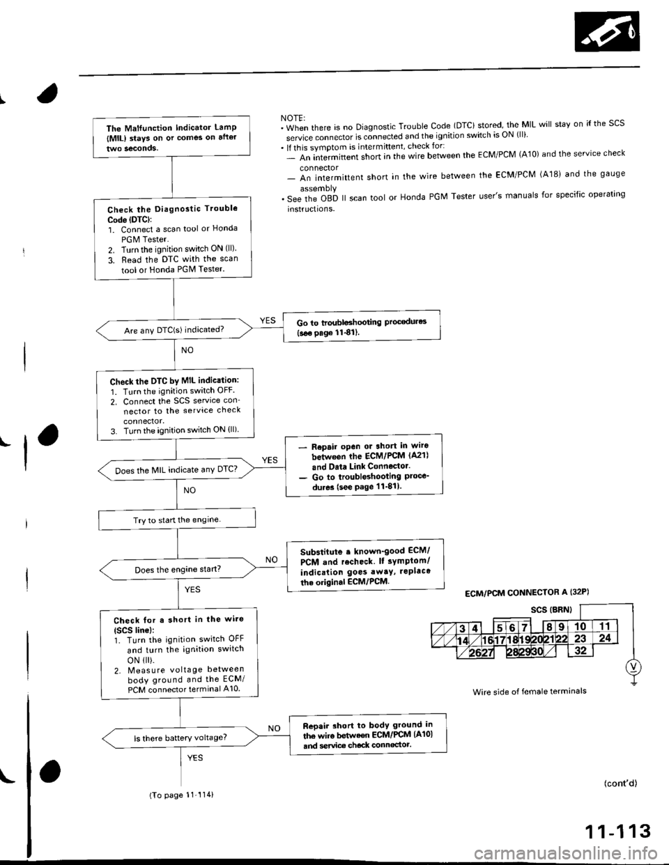
NOTE:"in-"n tf'"r" is no Diagnostic Trouble Code (DTCi stored, the MIL will stav on ;{ the scs
service connector is connected and the ignition switch is ON (ll)
. lf this symptom is intermittent, check for:- An intermittent short in the wire between the ECM/PCM (A10) and the service check
connector- An intermittent short in the wire between the ECM/PCM (A181 and the gauge
. s"" it'" Oab ll scan tool or Honda PGM Tester user's manuals for specific operating
instructions.
'l
ECM/PCM CONNECTOR A I32P)
Wire side of female terminals
The Malfunction Indicator LamP
lMlL) staYs on or comes on after
Check the Diagnostic Trouble
Code (DTC):
1. Connect a scan tool or Honcla
PGM Tester.
2. Turn the ignition switch ON (ll)
3. Read the DTC with the scan
tool or Honda PGM Tester.
Go to troubloshooting Proc€dures(see page 1141).Are any DTC(S) indicated?
check the DTC by MIL indic.tion:
1. Turn the ignition switch OFF
2. Connect the SCS service con_
nector to the service check
3. Turn the ignition switch ON (ll)
Repair open or 3hort in wiro
between ihe ECM/PCM (A21)
and Data Link Connector.
Go to troubleshooting Ploce_du.es (see page 11-811.
Does the MIL indicate anY DTC?
Try to start the engine
Substitute . known-good ECM/
PCM and recheck lt sYmptom/
indication goes awaY, rePlaca
th. original ECM,/PCM.
Check for a short in the wi.e(Scs line):1. Turn the ignition switch OFF
and turn the ignition switch
oN 1 ).2- Meas u re voltage between
body ground and the ECM/
PCM connector terminal A10
Reoair short to body ground in
the wiro bstwaen ECM/PCM (A101
and service ch€ck connoctot.ls there battery voltage?
(To page 11-'114)
(cont'd)
1 1-1 13
Page 383 of 2189
PGM-FI System
Engine Gontrol Module/Powertrain Control
('99 - 00 Models except Dl6Y5 engine with
Module (ECM/PCMI
M/T) (cont'dl
{From page 11 1 l3)
Check for a short in the wi.e lMlLlinelr1. Turn the ignition switch OFF.2. Disconnect the ECM/PCM connector A (32P).3. Turn the ignition switch ON (ll).
Repair shorl to body ground inthe wire between the ECM/PCM{A18}and MlL.
ls the MIL ON?
Substituto a known-good ECM/PCM and r€check. lf symptom/indication goes away, roplacethe o.iginal ECM/PCM.
11-114
Page 387 of 2189
PGM-FI System
(From page 11-117)
ls approx. 2 kPa ('15 mmHg, 0.6in.Hg) or less indicated?
Check for a short in ihe wire{MAP line)l1. Turn the ignition switch OFF.2. Disco n nect the ECM/pCMconnector D (16P).
3. Check for continuity betweenthe MAP sensor connector No.3terminal and body ground.
R6pair lhort in tha wire b€twaenECM/PCM {D3l .nd MAP !6ru0r.
Substitute a known-good ECM/PCM..nd recheck. normal MAPis indiceted, .eplsce lhe originalECM/PCM,
Manifold Absolute Pressure (MAp) Sensor('96 - 98 Models,'99 - 00 D16Y5 engine with M/Tl (cont,d)
MAP SENSOR 3P CONNECTOR IC1l1I
MAP(RED/GRNI
Wire side of femate;rminats
11-118
Page 389 of 2189
PGM-FI System
Manifold Absolute Pressure (MApl Sensor('99 - 00 Models except Dl6yS engine with M/T) (cont,dl
MAP SENSOn 3P CONNECTOB tcllilt
MAP(RED/GRNI
Wire side of female terminals
(From page 11 119)
Check for an open or shon in theMAP s€nsor:Check the MAP with the scantool.
ls approx. 2 kPa (15 mmHg,0.6 in.Hg) or less indicated?
Check tor a sho.t in lhe wire{MAP line):1. Turn the ignition switch OFF.2. Discon n ect the ECN4/pCN4connector C (31P).3. Check for continuity betweenthe MAP sensor connector No. 3terminal and body ground.
Repair short in the wire betweenECM/PCM {Cl7} and MAp s€n-sor.
Substitute a known-good ECM/PCM and rech6ck. lf no.mal MApis indicated, replace the o.iginalECM/rcM.
11-120
Page 394 of 2189

IIntake Air Temperature (lATl Sensor
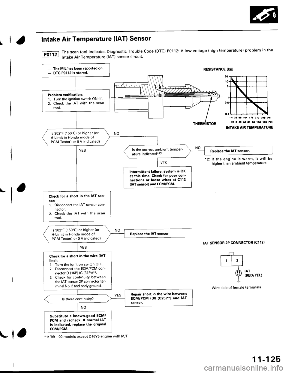
The scan tool indicates Diagnostic Trouble Code {DTC) P0112: A low voltage (high temperature) problem in the
lntake Air Temperature (lAT) sensor circuit.
RESISTANCE IKOI
.-l
*2: lf the engine is warm, it will be
higher than ambient temPerature.
IAT SENSOR 2P CONNECTOR {C112)
. a2 .. toa rra rrl l:rt t.al20 0 20 ro ao ao too t2ot.cl
INTAXIE AIR TEMPEFATURE
IAT{RED/YEL)
termrnars
-+-r
I'l'l-_T-
I=
Wire side of female
The MIL has been Teported on.
DTC P0112 is stored.
Problem verification:1. Turnthe ignition switch ON 1ll)2. Check the IAT with the scan
tool-
ls 302'F (150"C) or hagher (or
H Limit in Honda mode ot
PGM Tester) or 0 V indicated?
ls the correct ambrent temper
ature indicatedi'�?Roolac€ tho IAT 3ensor.
lntermittent failure, svstom is OK
6t this tim€. Check for Poor Gon-
nections or loos€ wires st C112
{lAT.en3orl and ECM/PCM.
Check tor a shon in the IAT sen-
sor:1. Disconnect the IAT sensor con
nector.2. Check the IAT with the scan
tool.
ls 302"F (150'C)or higher (or
H'Limit in Honda mode of
PGM Tester) or 0 V indicated?
Ch6ck for s short in the wira (lAT
lin€):1. Turn the ignition switch OFF
2. Disconnect the ECM/PCM con-
nector D (16P) (C (31P))*'.
3. Check for continuity between
the IAT sensor 2P connector ler-
minal No. 2 and body ground.
Reoair short in the wire bstweenECM/PCM tD8 (c25)'1) and IAT
Substitute a known-good ECM/
PCM and recheck. It normel IAT
is indicated, replace the original
ECM/PCM.
* l: '99 - 0O models except Dl6Y5 engine with M/T-rf,
11-125
Page 398 of 2189

|.
'f
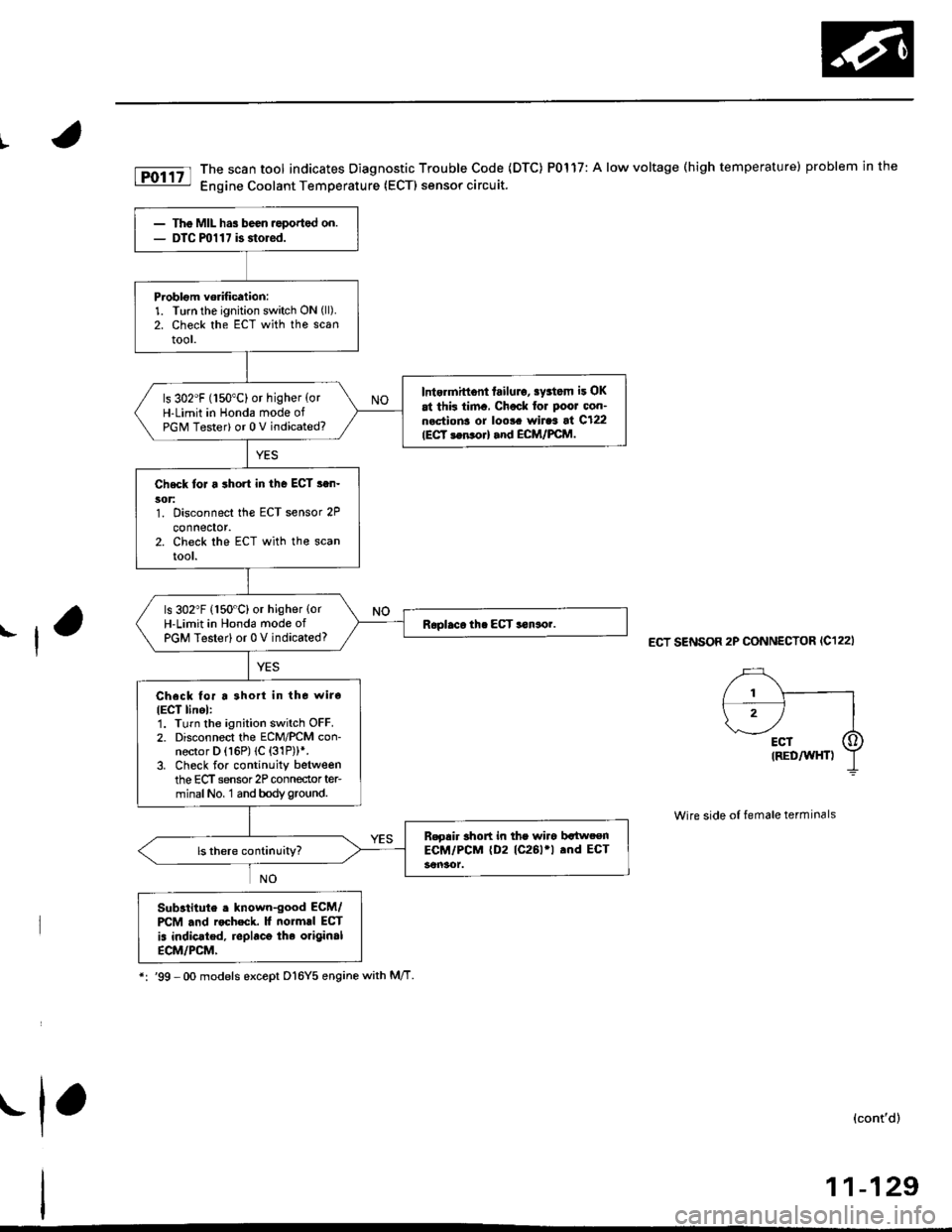
fD;r.tt The scan tool indicates Diagnostic Trouble Code (DTC) P0117: A low voltage (high temperature) problem in the|jg Engine Coolant Temperature (ECTI sensor circuit.
ECT SENSOR 2P CONNECTOR (C122I
Wire side of female terminals
Substitute . lnown-good ECM/PCM .nd rocheck. It normrl ECT
is indic.ted, replaco the original
ECM/PCM,
*:'99 -Oo models except D16Y5 enginewith M/T
(cont'd)
11-129
The MIL has been ,eported on.DTC ml 1 7 is storod.
Problom vorification:1. Turn the ignition switch ON (ll).
2. Check the ECT with the scantool.
Intermittont failulo, sy3tom it OK
at thk tim., Chock for Poor oon-n.ctions or loo!. wiraa at C122IECT 3en orl and ECM/FCM.
ls 302"F (150"C) or higher {orH-Limit in Honda mode ofPGM Tester) or 0 V indicated?
Check toJ a short in the ECT s.n-5('t:1. Disconnect the ECT sensor 2P
connector.2. Check the ECT with the scanrool.
ls 302"F (150"C) or higher {orH-Limit in Hond6 mode ofPGM Testerl or 0 V indicated?
Check for a 3hort in tho wiro
IECT linel:1. Turn the ignition switch OFF.2. Disconnect the ECM/PCM con-nector D (16P) (C {31P))*.3. Check for continuity betweenthe ECT sensor 2P conneclor ter-minalNo, 1 and bodyground.
B.gair short in the wiro bltweenECM/PCM (D2 (C261'l .nd ECT
.1,