1998 HONDA CIVIC Ignition wire resistance
[x] Cancel search: Ignition wire resistancePage 430 of 2189

Heated Oxygen Sensor (HO2SI Heater (Dl6Y5 engine with M/Tl
The scan tool indicates Diagnostic Trouble Code (DTC) P1166: An electrical problem in the Primary Heated
Oxygen Sensor (Primary H02S) Heater system.
PRIMABY HO2S ISENSOR 1I 8P CONNECTOR
Terminal side ofmale terminals
I(cont'd)
11-161
- The MIL has been lePorted
- DTC Pl166 b stored.
Problem verilication:1. Do the ECM Reset Procedure.
2. Start the engine.
Intermitlent failura, sYstem b OK
at this time (te3t drive maY be
ngcessary). Check for poor con-
nections or loose wires between
C145 (Primary HO2S, Sen3or 1l
end ECM.
ls DTC P'l166 indicated?
Check the Primary HO2S (Sensot
1l resistence:1. Turn the ignition switch OFF
2. Disconnect the Primary HO2S(Sensor 1) 8P connector.
3. At the Primary HO2S (Sen
sor 1), measure resistance
between No. 1 and No. 2 ter_
Replace lhe Primery HO2S (Sen-
sor 11.ls there 2 13 O?
Check for a shorted PrimarY
HO2S lsensor 1):Check for continuity between
body ground and each terminal.
Check for a shorted PrimarY
HO2S {S€nsor 1l:
Check for continuity between ter'
minal No. 1 and terminals No.3,
4, 6, 7 and 8 individually.
ls there conlrnuily?
(To page 11'162)
Page 442 of 2189

(From page | 1-172)
Check fo. a sho.t in the CKP/
TDC/CYP sensor:Check for continuity to bodYground on both terminals of the
indicated senso r individually
1*see table).
Replaco the di3tributor ignition
hoGing lsee section 23).ls there continuity?
Check for an open in the wires
ICKP/TOC/CYP line3):1. Reconnect the distributor 10P
connecaor.2. Disconnect the EcM/PCM con-
nector C {31P}.3. N4easure resistance betweenthe terminals of the indicated
sensor on the ECIM/PCM con-
nector {*see tabie}.
Repair open in the indicated sen-
sor wires lrsee tablel.ls there 350 - 700 o?
Chock lor. short in the wires
ICKP/TDC/CYP lines):
Check for continuity between
body ground and ECM/PCM con-
nector terminals C2, C3 and/or C4individually.
Repai. short in the indic.ted sen_
sor wire3 ('soe tablol,ls there continuity?
Substitute e known-good ECM/PCM, and iecheck. ll sYmptom/indication goes awev, r€Place the
original ECM/PCM.
DISTRIBUTOR10P CoNNECTOR {C1201
Terminalside ofmale terminals
ECM/PCM CONNECTORS C 131P)
CI(P P TDC P CYP P(YEL)
M
CKP M(WHT)MIBLKI
Wire side offemale terminals
CYP PIYELI
(REDI
TDC P(GRN)CKP P(BLU}
t
TDC P (GRNI
11-173
Page 443 of 2189

PGM-FI System
l-Fos3sl
tFos36l
tF1361 l
Fr362-1
tF13sil
Crankshaft Position/Top Dead Center/Cylinder Position (CKP/TDC/CYPI Sensor
f99 - 00 Models except D16Y5 engine with M/T)
The scan tool indicates Diagnostic Trouble Code (DTC) P0335: A malfunction in the Crankshaft Position (CKP)
sensor circuit.
The scan tool indicates Diagnostic Trouble Code (DTC) P0336: A range/performance problem in the Crankshaft
Position (CKP) sensor circuit.
The scan tool indicates Diagnostic Trouble Code (DTC) P1361: Intermittent interruption in the Top Dead Center
{TDC) sensor circuit.
The scan tool indicates Diagnostic Trouble Code {DTC) P1362: No signal in the Top Dead Center (TDC) sensor
circuit.
The scan tool indicates Diagnostic Trouble Code (DTC) P1381: Intermittent interruption in the Cylinder Position(CYP) sensor circuit.
lTiaSt The scan tool indicates Diagnostic Trouble Code (DTC) P1382; No signal in the Cylinder Position (CYP) sensor: circuil.
DoscriDtion
The CKP Sensor determines timing for fuel injection and ignition of each cylinder and also detects engine speed. The TDC
Sensor determines ignition timing at start-up (cranking) and when crank angle is abnormal. The CYP Sensor detects the
position of No. 1 cylinder for sequential fuel injection to each cylinder. The CKP/TDC/CYP Sensor is built into the distribu-
tor.
NOTE; lf DTC P1359 is stored at the same time as DTC P0335, P0336, P1361. P1362, P1381 and/or P1382, troubleshoot DTC
P1359 first, then recheck for those DTCS. D16Y5 engino:
SENSORROTOR
TDGSENSORCKPSENSOBTDCSENSOBCKPSENSOBCYPs€NsonBOTORROTORBOTONROTOR ROTOR
D16Y7, D16Y8 ongine:
(To page 11-175)
1-174
- The MIL has been reportod on.- DTC P0335, P0336. P1361,P1362, P1381 rnd/or P1382.restored.
Problem verific{tion:1. Do the ECM/PCM Reset Proce-dure.2. Start the engine.
Intormittcnt failure, systom b OKat thb time. Check to. poor con-nections or loose wires at C120(dktributorl and ECM/PCM.
ls DTC P0335, P0336, P1361, P1362,P1381 and/or Pl382 indicated?
Check tor an open in the CKP/TDC/CYP 3enior:1. Turn the ignition switch OFF.2. Disconnect the distributor 10Pconnector,3. Measure resistance betweenthe terminals of the indicatedsensor (*see table).
Replrce the distributor ignitionhou3ing (!ee section 231.ls there 350 700 0?
SENSORDTCSENSORTEBMINAIECM/PCMTERI\,4INAICOLOR
CKPP0335
P0336
2c88LU
6c9
TDCP1361
P1362
3c20GRN
7c21BED
CYPP1381
P1342
c29YEL
Ic30BLK
Page 467 of 2189

ldle Control System
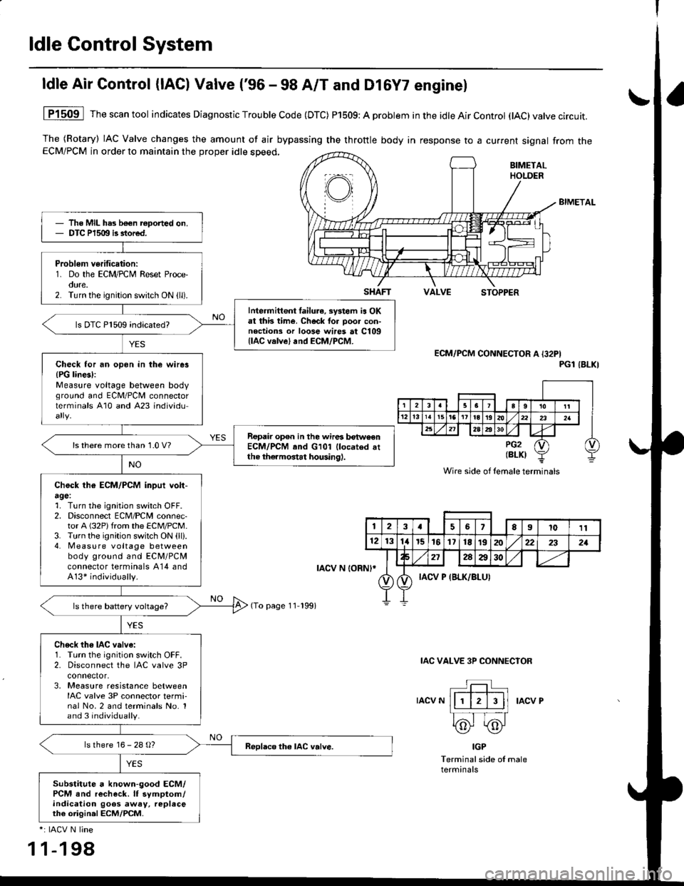
ldle Air Control (lAC) Valve ('96 - 98 A/T and Dl6Y7 enginel
The (Rotary) IAC Valve changes the amount of air bypassing the throttle body in response to a current signal from theECM/PCM in order to maintain the proper idle speed,
BIMETAL
VALVESTOPPER
1P1509 Thescantool indicates Diagnostic Trouble Code (DTC) P1509: A problem in the idle Air Control (tAC)valve circuit.
ECM/PCM CONNECTOR A I32PIPGl IBLKI
IAC VALVE 3P CONNECIOR
IACV NIACV P
IGP
Terminal side of maleterminals
*: IACV N line
1 1-198
The MIL has b€€n roported on.DTC P1509 is stored.
Problem verification:1. Do the ECM/PCM Reset Proce-oure.2. Turn the ignition switch ON (ll).
Intermittent failura, systom ia OKat this time. Check tor poo. con-noctions or loose wires at C109llAC valve) and ECM/PCM.
ls DTC P1509 indicated?
Check for an opon in the wirer{PG lines):Measure voltage between bodvground and ECM/PCII connectorterminals A10 and A23 individu
Repair op€n in the wires betwoenECM/PCM and G101 llocated attho thermostat housing).
ls there more than 1.0 V?
Chock th€ ECM/PCM inpui volt-agel1. Turn the ignition switch OFF.2. Disconnect ECM/PCM connec-tor A (32P)from the ECM/PCM.3. Turn the ignition switch ON (ll).4. Measu re voltage betweenbody ground and ECM/PCMconnector terminals A14 andA13* individually.
Ch6ck th6 IAC valve:1. Turn the ignition switch OFF.2. Disconnect the IAC valve 3Pconnector,3, Measure resistance betweenIAC valve 3P connector termi-nal No.2 and terminals No. 1and 3 individually.
ls there 16 - 28 g?
Substitute a known-good ECM/PCM and recheck. lf symptom/indication goos away, replaceth€ origin.l ECM/PCM.
SHAFT
rAcv N loRNl*
(To page 11-199)
Wire side of lemale terminals
123a56El011
121314r5161718t9202:22321
272AA30
IACV P {BLK/BLUI
Page 468 of 2189

t
lFrom page 11-198)
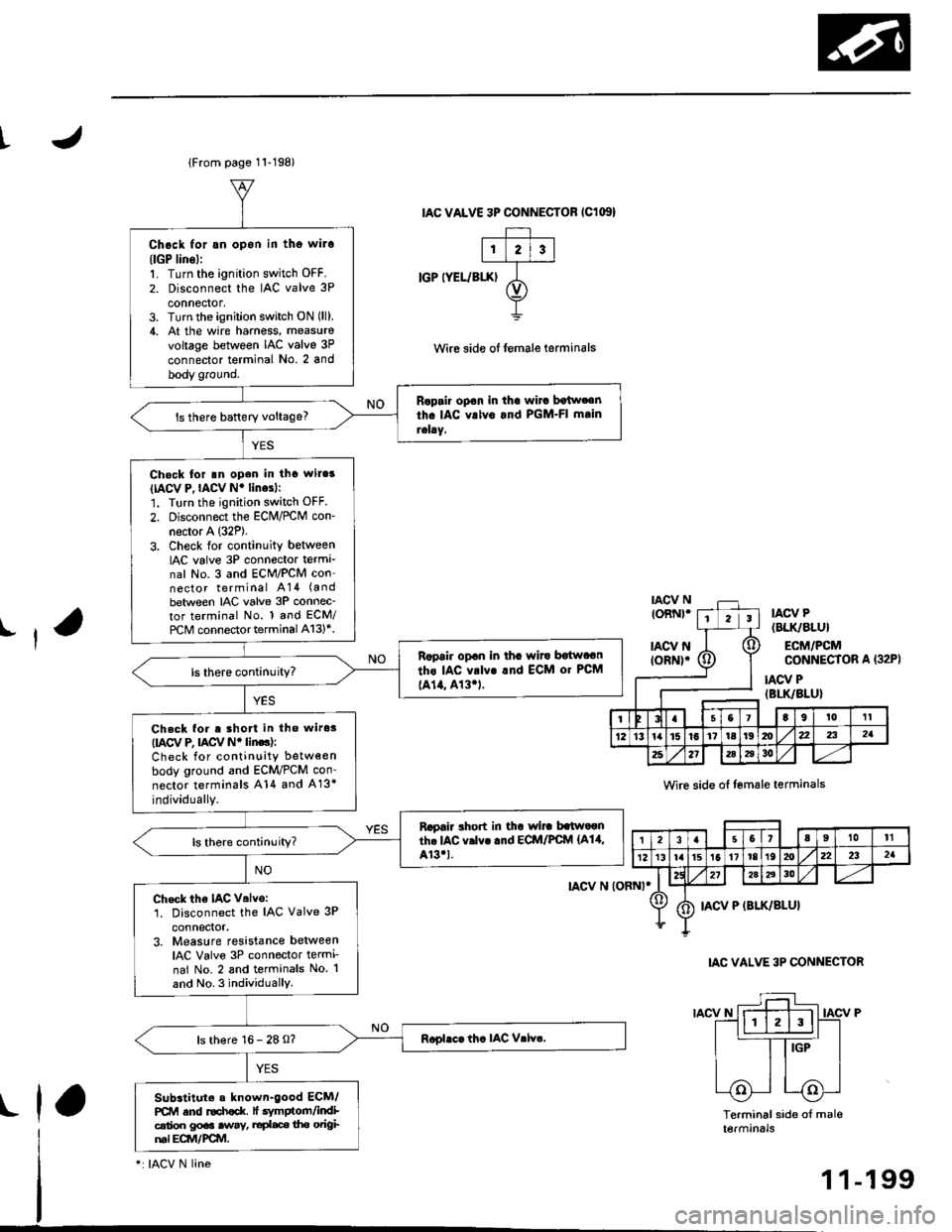
Chock for an opon in tho wilo(lGP lins):'1. Turn the ignition switch OFF.
2. Disconnect the IAC valve 3P
connector,3. Turn the ignition switch ON (ll),
4. At the wire hamess, measure
voltage between IAC valve 3P
connector terminal No. 2 and
body ground.
Raprir op€n in th€ wirc botw.€nth. IAC vrlv6 and PGM.FI mtin
rehy.ls there baftery voltage?
Check for rn open in tho wil.s(IACV P,IACV Nr linesl:
1. Turn the ignition switch OFF.
2. Disconnect the ECM/rcM con-
necror A (32P).
3. Check for continuity betweenIAC valve 3P connecto. terma_nal No. 3 and ECM/PCM con-nector terminal A14 (a nd
between IAC valve 3P connec-tor terminal No. 1 and ECM/
rcM connector terminal A13l*.
Ropair opan in tha wito bgtwoon
ths IAC vrlv! rnd ECM or PCM
{A14, 413.1.
Check for e lhort in tho wiros(IACV e nCV Nr linc):
Check for continuity between
body ground and ECM/PCM con-
nector terminals A14 and A13*
individually.
Rapair rhort in thr wi]. batwaonth. IAC v.lvc .nd ECM/PCfvl {A14,Ar3.t.ls there continuity?
Check the IAC V.lvo:1. Disconnect the IAC Valve 3P
3. Measure resistance betweenIAC Valve 3P connector termi-
nai No. 2 and terminals No. 1
and No. 3 individuallY.
ls there 16 - 28 O?
Subrtituto a known-good ECM/PCM and r€ch€d( lt .vmptom/indicalioo gp€. .way, ruplace tho odgiml Eqvt/FCM.
IAC VALVE 3P CONNECTOR IClG'}
IGP IYEL/BIX)
tAcv N (oRNt*
IACV N
Wirc side of lemale teaminals
IAC VALVE 3P CONNECTOR
IACV P
Terminal side of mal6tetmtnats
(32P)
ll
toRNt*tIIACV P(BLK/8LU}
ECM/PCMCONNECIOR A
IACV P(BLK/BLU}
Io,tl0't1
1Z13ta15l617tal9mx22321
2521i6a3o
,|31.57aIl0tl
12t3r. lrst511r8t92022232a
272aA30
IACV P (BLK/SLU}
rla
-: IACV N line
1 1-199
Page 469 of 2189

ldle Gontrol System
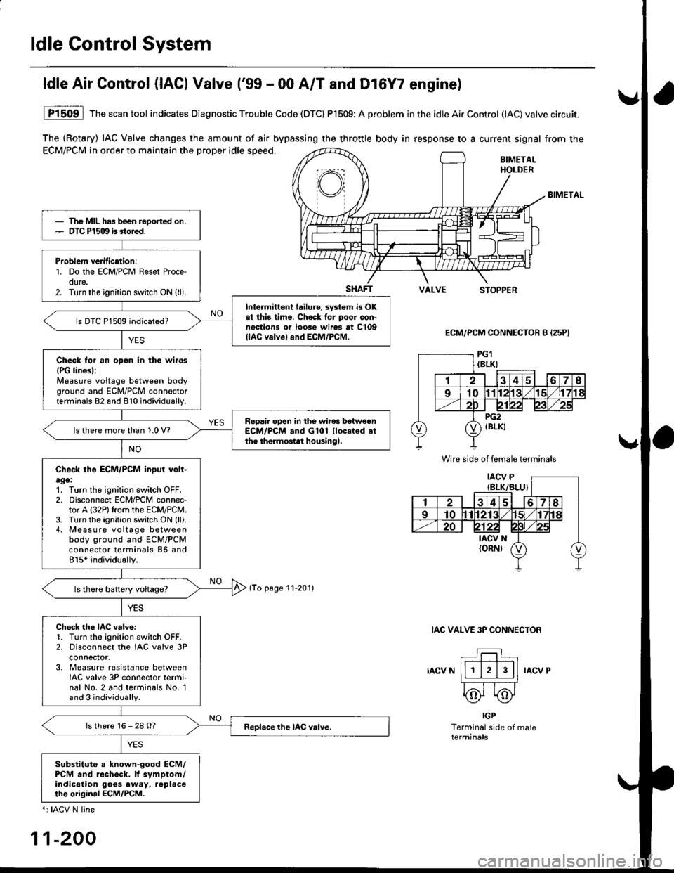
The (Rotary) IAC Valve changes the amount of air bypassing the throttle body in response to a current signal from the
ECM/PCM in order to maintain the proper idle speed.BIMETALHOLDER
BIMETAL
SHAFTVALVESTOPPER
ECM/PCM CONNECTOR B {25P}
(To page 11-201)
IAC VALVE 3P CONNECTOR
IACV NIACV P
ldle Air Control {lACl Valve ('99 - 00 A/T and Dl6Y7 enginel
YES
1P1509 lThescantool indicates Diagnostic Trouble Code (DTC) P1509:A problem inthe idleAirControl (lAC)valve circuit.
IGP
Terminal side of maleterminals
Sub3titute e known-good ECM/PCM .nd recheck. lf 3vmptom/indicalion goos away, replac6thc original ECM/PCM.
*: IACV N line
11-200
Tho MIL has b€en reported on.OTC P1509 is sto.ed.
Problem verilicationr1. Do the ECM/PCM Reset Proce-dure.2. Turn the ignition switch ON (ll).
Intermittont tailure, sy3tem i3 OKat thb time. Check for poor con'noctions or loose wiros at C109(lAC velvel and ECM/PCM.
ls DTC P1509 indicated?
Check for an oDen in the wilosIPG linesl:Measure voltage between bodyground and ECM/PCM connectorterminals 82 and 810 individually.
Ropail open in the wires be'tw€enECM/PCM .nd G101 llocated .tthe the.mostat housingl.ls there more than 1.0 V?
Check tho ECM/PCM input volt-age:1. Turn the ignition switch OFF.2. Disconnect ECM/PCM connec-tor A (32P)trom the ECM/PCM.3. Turn the ignition switch ON (ll).
4, Measure voltage betweenbody ground and ECM/PCMconnector terminals 86 and815* individually.
Chock the IAC v.lve:1. Turn the ignition sw;tch OFF.2. Disconnect the IAC valve 3Pconnoctor.3. Measure resistance betweenIAC valve 3P connector termi'nal No. 2 and terminals No. 1and 3 individually.
ls there 16 - 28 O?
Wire side of female terminals
Page 527 of 2189

Emission Gontrol System
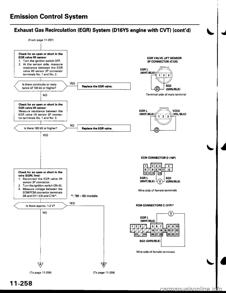
Exhaust Gas Recirculation (EGRI System (Dl6Y5 engine with CW) (cont'dl
EGR VALVE LIFT SENSOR3P CONNECTOR {Cl251
./
EGR L(WHT/BLKI
EGR LIWHT/BLKI
EGR L{WHT/BLKI
sG2
{GRN/BLK}
sG2{GRN/BLK}
Terminal side ol male terminal
ECIT'I CONNECTOR D II6PI
Wir€ side of f€male terminals
PCM CONNECTORS C (31PI*
{To page 11-259)
11-258
{From page 11-257}
Chock lor an opcn or short in th.EGR v.lve lift .€nsor'1. Turn the ignition switch OFF.2. At the sensor sid€, measur€resistance between the EGRvalve lift sensor 3P connectorterminals No. 1 and No.2.
ls there continuity or resis'tance ot 100 k0 or higher?
Chock tor sn op€n or lhort in theEGR valve lift lonror:Measure resistancg between theEGR valve lift s€nsor 3P connec-tor terminals No. 1 and No. 3.
ls there 100 k0 or higher?
Ch.ck tor an ooon or rhon in thcwiro IEGRL linc):1. Beconnect tho EGR v6lve liftsensor 3P connector.2. Turn tho ignition switch ON (ll).
3. Measure voltage between theECM/PCM connector terminalsD9 and Dl1 (C6 and C18l*.
ls there approx. 1.2 V?
(To page 11-259)
Wire side of female terminals
Page 531 of 2189

Emission Control System
(From page 11-261)
Check tor open in the wire (SG2
linel:Measure voltage between theECM connector terminals D10and D11.
Repsir open in lhe wire beiweenECM lOllland EGR valve.ls there approx. 5 V?
Check the EGR valve:1. Turn the ignition switch OFF.2, At the sensor side, measureresistance between the EGRvalve 6P connector terminalsNo. 1 and No. 2.
ls there continuity or resis-tance of 100 k0 or higher?
Check the EGR valve:Measure resistance between theEGR valve 6P connector terminals No. 1 and No.3.
ls there 100 k0 or higher?
Exhaust Gas Recirculation System (D16Y5 engine with M/T) (cont'dl
ECM CONNECTOR D {16P)
vcc2(YEL/BLU)
\v
sG2IGRN/BLK)
Wire side of female term;nals
EGR VALVE 6P CONNECTOR
EGR L(WHT/
BLK}
SG2 (GRN/BLK)
Termanal side of male terminals'l'
EGR L{WHT/BLK}
vcc2
{YEL/BLU}
(To pase 11 263)
1-262