Page 1021 of 2189
l.
60. Install the ditferential assembly
61. Installthe ATF passage line assembly with new O-rings (one boltl'
62. Install thethreedowel pinsand new flywheel housing gasket on the transmission housing'
63. Install the flywheel housing and connector bracket (twenty bolts)'
64. Installthe ATF passage line holder assembly (two bolts)'
8 x 1.25 mm29 N.m t3.o kg['m, 22 lbf'ttl
IATF PASSAGE L|NE I"o.o.'o{
d
rm
\A
o-nrnc--.-..ff
FLYWHEEL HOUSINGGASKET
6x1.0mm12 N.m {1.2 ksf'm,
8.7 tbf.ftl/g
ugs llFLYWHEEL HOUSING
CONNECTOR BRACKET
DOWEL PIN
DIFFERENNAL ASSEMBLY
DOWEL PIN
ATF PASSAGE LINE
ASSEMALY
6x1.0mm12 N.m 11.2 kgd'm,
8.7 tbr.tr)
O.RING
DOWEL PIN
TRANSMISSIONItousrNG
ATF PASSAGELINE ASSEMBLY
PASSAGE LINEGUIOE
(cont'd)
TRANSMISSION HOUSING
14-345
Page 1024 of 2189

Transmission
Installation
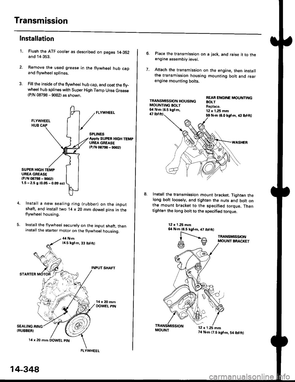
Flush the ATF cooler as described on pages 14-352and 14-353.
Remove the used grease in the flywheel hub caDand flywheel splines.
Fill the inside of the flywheel hub cap, and coat the fly-wheel hub splines with Super High Temp Urea Grease(P/N 08798 - 9002) as shown.
L
SEALING RING{RUEBER)
SPLINESApply SUPEB HlcH TEMPUREA GREASElPlN 08798 - 90O2t
SUPER HIGH TEMPUREA GREASE(P/N 08798 - !)00211.5-2.5 g 10.05-0.t9 oz)
Install a new sealing ring (rubber) on the inoutshaft, and install two '14 x 20 mm dowel Dins in theflywheel housing.
Install the flywheel securely on the input shaft, theninstallthe starter motor on the flywheel housing.
4,1Nmla.5 kgt.m, 33 tbt.ft)
INPUT SHAFT
STARTER
l4 x 20 mm DOWEL ptN
.4;i "lrj
,i rr,"r., ., a
14-348
FLYWHEEL
MOUI{T74 N.m (7.5 tstm,5a tbtftt
6. Place the transmission on s jack, and raise it to theengine assembly level.
7. Anach the transmission on the engine, then installthe transmission housing mounting bolt and rearengine mounting bolts.
TRANSMISSION HOUSINGMOUNTING BOIT6,1 N.m 16.5 kgl.m,47 tbtttl59 Nrn {6.0 kgl.m. ,€ lbt ftl
WASHER
lnstall the transmission mount bracket. Tighten thelong bolt loosely, and tighten the nuts and bott onthe mount bracket to the specified torque. Thentighten the long bolt to the specified torque.
REAR ENGINE MOUNTINGBOLTReplace.12 x 1.25 mm
12x 1.25 mn6,r N'm 16.5 kgtm,47 tbtftl
l-".--..-,^
G\V
TRANSMISSONMOUNT BRACKET
12 x 1.25 mn
Page 1025 of 2189

l.
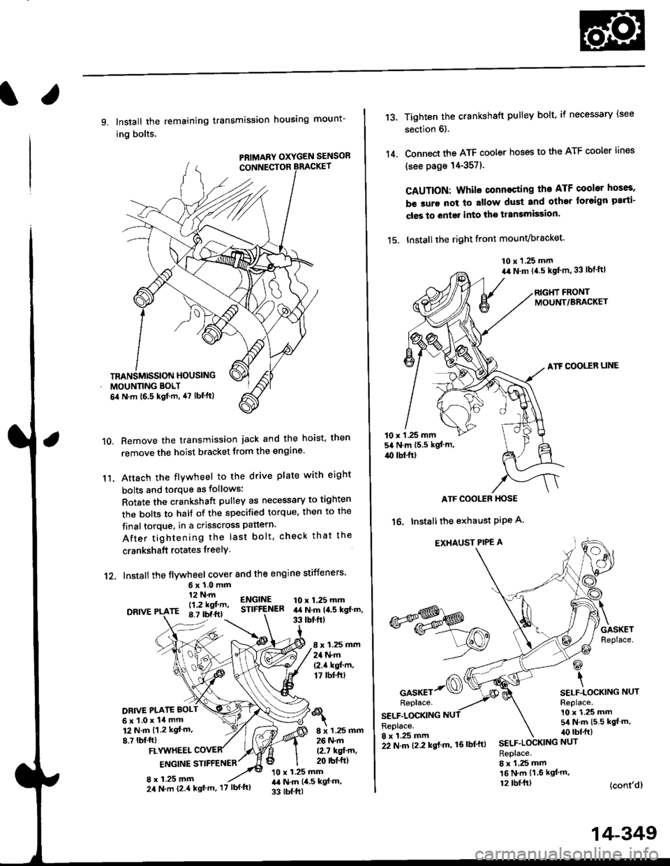
9. Install the remaining transmission housing mount-
ing bolts.
PRIMARY OXYGEN SENSOR
Remove the transmission jack and the hoist. then
remove the hoist bracket from the engine'
Attach the flvwheel to the drive plate with eight
bolts and torque as follows:
Rotate the crankshaft pulley as necessary to tighten
rhe bolts to half of the specified torque, then to the
final torque, in a crisscross pattern.
After tightening the last bolt. check that the
crankshaft rotates freelY.
10.
11.
12. Install the flywheel cover and the engine stiffeners
DRIVE
6xl.0mm12 N.m
- l12 kgf'm'rE 8.7 tbf.ftl
ENGINESTIFfENEB10 x 1.25 mmart N.m la.s kgt.m,33 tbtftt
8 x 1.25 mm24 N.m(2.1 kgf'm,17 tbt.ftt
DRIVE PI.ATE BOLT
6x1.0x14mm12 N.m {1.2 kgt m.
8.7 lbf,ftl8 x 1.25 mm26 N.m
12.7 kqfin,20 rbt'ftlFLYUTHEEL
ENGINE STIFFENER
8 x 1.25 mm10 x 1.25 mmr,a N.m {4,5 kgf m,
33 tbf.ftl
TRANSMISSION HOUSING
MOUNNNG BOLT
6il N.m {6.5 kgf.m, 47 lbf'ftl
24 N.m (2.4 kgt'm, '17 lbf'ftl
22 N.m t2.2 kgl m, 16lbf'ftl
14-349
13.
14.
Tighten the crankshaft pulley bolt, if necessary (see
section 6).
Connect the ATF cooler hoses to the ATF cooler lines
(see page 14-357).
CAUTION: Whilo connecting the ATF cooltr hGes,
b€ sure not lo allow dust and other loreign parti-
cles to entg. into the transmission.
15. Installthe right front mounvbracket'
10 x 1.25 mm
a,r N.m {4.5 kgf'm,33 lbt ftl
RIGHT FRONTMOUNT/BRACKET
ATF COOLER LINE
10 x 1 .25 mm54 N.m {5.5 kgt'm,
4{) tbl.ftt
ATF COOI,TR HOSE
16. Installthe exhaust PiPe A.
EXHAUST PIPE A
GASKETReplace.
@
\SELF.LOCKING NUTReplace.10 x 1.25 mm5/a N.m {5.5 kgt m,irc lbf.ft)
(cont'dl
*s$o
oor*rr-@Replace.
SELF.LOCKINGReplace.8 x 1.25 mmSELF.LOCKING NUT
Replace.8 x 1.25 mm16 N.m {1.6 kgl'm,12 tbl.ftt