Page 1401 of 2189

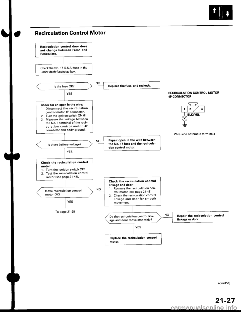
Recirculation control door does
not chango betwe€n Fresh and
Recirculate.
Check the No. l7 (7.5 A) fuse an the
underdash fuse/relay box.
Replace the fuse, and recheck.
Check lor an oPen in the wite:
1. Disconnect the recirculation
control motor 4P connector.
2. Turn the ignition switch ON (ll)
3. Measure the voltage between
the No. 1 terminal of the recir
culation control motor 4P
connector and body ground.
Repair open in the wire between
the No. 17 luse and lhe recircula-
tion control motor.ls there battery voltage?
Check the rccirculation control
motorr']� Turn the ignition switch OFF.
2. Test the recirculation control
motor (see Page 21 48i
Check the recirculation control
linkage and door:1. Remove the recirculation con_
trol motor lsee Page 2l 48).
2. Check the recirculation control
linkage and door for smooth
movement.
Reoair the recirculation conlrol
linkag€ or door.Do the recirculation control link_
age and door move smoothlY?
CONTROL MOTOR
side of temale terminals
RECIRCULATION CONTRC,lP CONNECTOR
q-?--T--T--T-|1l2l/l1l
f BLK/YEt(v)
!
page
(cont'd)
Page 1679 of 2189

Function Test
CAUTION: Be careful not to damage the mirror switch
or the dashboard drivel's lower covel when prying the
swhch out.
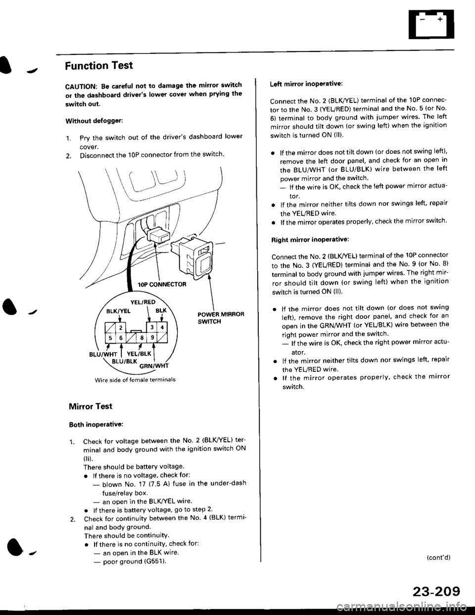
Withoui defogger:
1. Pry the switch out of the driver's dashboard lower
cover.
2. Disconnect the 10P connector from the switch.
lOP CONNECTOR
BLU/WHT
YEL/RED
BLK/YELBLK
4
568
YEL/BLK
POWER MIRRORswtTcH
\:/"*jgil*-(
Wire side of female termanals
Mirror Test
Both inoperative:
1. check for voltage between the No. 2 (BLVYEL) ter
minal and body ground with the ignition switch ON
0 r).
There should be batterY voltage
. If there is no voltage, check for:
- blown No. 17 (7 5 A) fuse in the under-dash
tuse/relay box- an open in the BLK'/YEL wire.
o lf there is battery voltage, go to step 2.
2. Check for continuity between the No 4 (BLK) termi-
nal and body ground.
There should be continuity.
. lf there is no continuity, check for:
- an open in the BLK wire.
- poor ground (G551).
Left mirror inoporalive:
connect the No. 2 {BLK/YEL) terminal of the 10P connec-
tor to the No. 3 (YEURED) terminal and the No 5 (or No
6) terminal to body ground with jumper wires The left
mirror should tilt down (or swing left) when the ignition
switch is turned ON (ll)
. lf the mirror does not tilt down (or does not swing left),
remove the left door panel. and check for an open in
the BLU/WHT (or BLU/BLK) wire between the left
power mirror and the switch
- lf the wire is OK. check the left power mirror actua-
tor.
lf the mirror neither tilts down nor swings left. repair
the YEURED wire.
lf the mirror operates properly, check the mirror switch'
Right mirror inoperative:
Connect the No. 2 (BLK /EL) terminal of the 10P connector
to the No. 3 (YEURED) terminal and the No. 9 (or No 8)
terminal to body ground with jumper wires The right mir-
ror should tilt down (or swing left) when the ignition
switch is turned ON (ll).
. lf the mirror does not tilt down (or does not swlng
left), remove the right door panel. and check for an
open in the GRN/WHT (or YEUBLK) wire between the
right power mirror and the switch.
- lf the wire is OK, check the right power marror actu-
ator.
. lf the mirror neither tilts down nor swings left. repair
the YEURED wire
. lf the mirror operates properly, check the mirror
switch.
(cont'd)
23-209
Page 1698 of 2189
Power Windows
Master Switch Input Test {Coupe/Hatchback)
NOTE: The control unit is built into the power window master switch, and only controls driver's door window operatlons.
l� Remove the driver's door panel, and disconnect the 12P connector from the master switch.
2. Inspect the connector and socket terminals to be sure they are all making good contact.
. lf the terminals are bent, loose or corroded, repairthem as necessary, and recheck the system.
. lf the terminals look OK, make the following input tests at the connector.- lf a test indicates a problem, find and correct the cause. then recheck the system.- lf all the input tests prove OK, the power window master switch must be faulty; replace it.
23-228
Ware side of female terminals
Page 1700 of 2189
Power Windows
Master Switch Input Test (Sedan)
NOTE: Thecontrol unit is built intothe power window master switch, and only controls driver's door window operations.
1. Remove the driver's armrest, and disconnect the 16P and 1P connectors from the master switch.
2. Inspect the connector and socket terminals to be sure they are all making good contact.
a lf the terminals a re bent, loose orcorroded, repairthem as necessary, and recheck the system.
. lf the terminals look OK, make the following input tests at the connector.- lf a test indicates a problem, find and correct the cause, then recheck the system.- lf all the input tests prove OK. the power window maser switch must be faulty; replace it.
POWEB WINDOW MASTER SWITCH
23-230
Page 1727 of 2189
Control Unit Input Test ('96 - 98 models and'99 - 00 models without
Keyless Entry System)
1. Remove the driver's door panel (see section 20).
2. Disconnect the 12P connector from the control unit.
3. Inspect the connector and socket terminals to be sure they are all making good contact
a lf the terminals are bent, loose or corroded, repair them as necessary, and recheck the svste-
. lf the terminals look OK, make the following input tests at the connector.
- lf any test indicates a problem, find and correct the cause, then recheck the syslem
lf all the input tests prove OK, the control unit must be faulty; replace it.
.I2P CONN€CTOR
Wire side o{ femele terminals
*: With keyless entry system
l-llcont d)
23-257
YEL/RED
BLU/RED
15
1812
BLU/WHT
Page 1729 of 2189

)Control Unit Input Test ('99 - 00 models with Keyless Entry System)
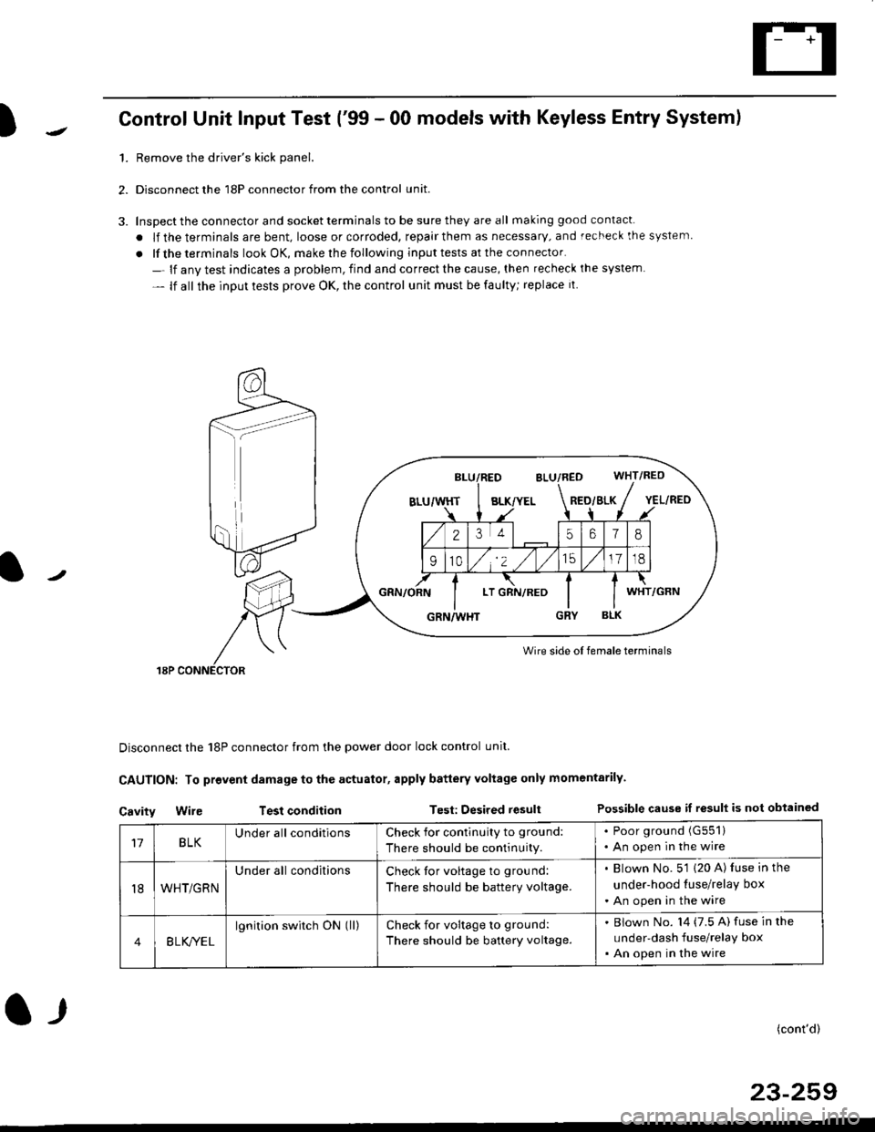
1.Remove the driver's kick panel.
Disconnect the 18P connector from the control unit.
Inspect the connector and socket terminals to be sure they are all making good contacl.
. lf the terminals are bent, loose or corroded, repair them as necessary, and recheck the system
. lf the terminals look OK, make rhe following input tests at the connector.
- lf anv test indicates a problem, find and correct the cause, then recheck ihe system
- lf all the input tests prove OK, the control unit must be faulty; replace it
Wire side oI female terminals
Disconnect the 18P connector from the power door lock control unit.
CAUTION: To provent damage to the actuator, apply battery Yoltage only momentarily.
Cavity Wir€ Test conditionTest: Desired resultPossible cause if result is not obtained
BLK/YELRED/SLK
25618
910/,'2 ,/
'151718
LTWHT
17BLKUnder all conditionsCheck for contlnuity to ground:
There should be continuity.
. Poor ground (G551)
. An open in the wire
t8WHT/GRN
Under all conditionsCheck tor voltage to ground:
There should be battery voltage.
. Blown No. 5'1 (20 A) luse in the
under-hood tuse/relay box
. An open in the wire
4B LK/YEL
lgnition switch ON (ll)check for voltage to ground:
There should be battery voltage.
Blown No. l4 (7.5 A) fuse in the
under-dash fuse/relay box
An open in the wire
(cont'd)
23-259
l-r
Page 1732 of 2189
Power Door Locks
Audio Unit {Keyless Receiver Circuitl Input Test ('96 - 98 models}
Remove the audio unit, then disconnect the A and B connectors (see page 23-189).
Inspect the connector and socket terminals to be sure they are all making good contact
. lf the terminals are bent, loose or corroded, repair them as necessary, and recheck the system
. lf the terminals look OK, make the following input tests at the connector.
- lf anv test indicates a problem, find and correct the cause, then recheck the system
lf all the inout tests prove OK, the control unit must be faulty; replace it.
A CONNECTOBB CONNECTOR
16P CONNECTORS
AUDIO UNIT
L
2.
WHT/BLU YEL/RED
{KEYLESS RECEIVER CIRCUIT}
23-262
Page 2030 of 2189

Power Door Locks (cont'd)
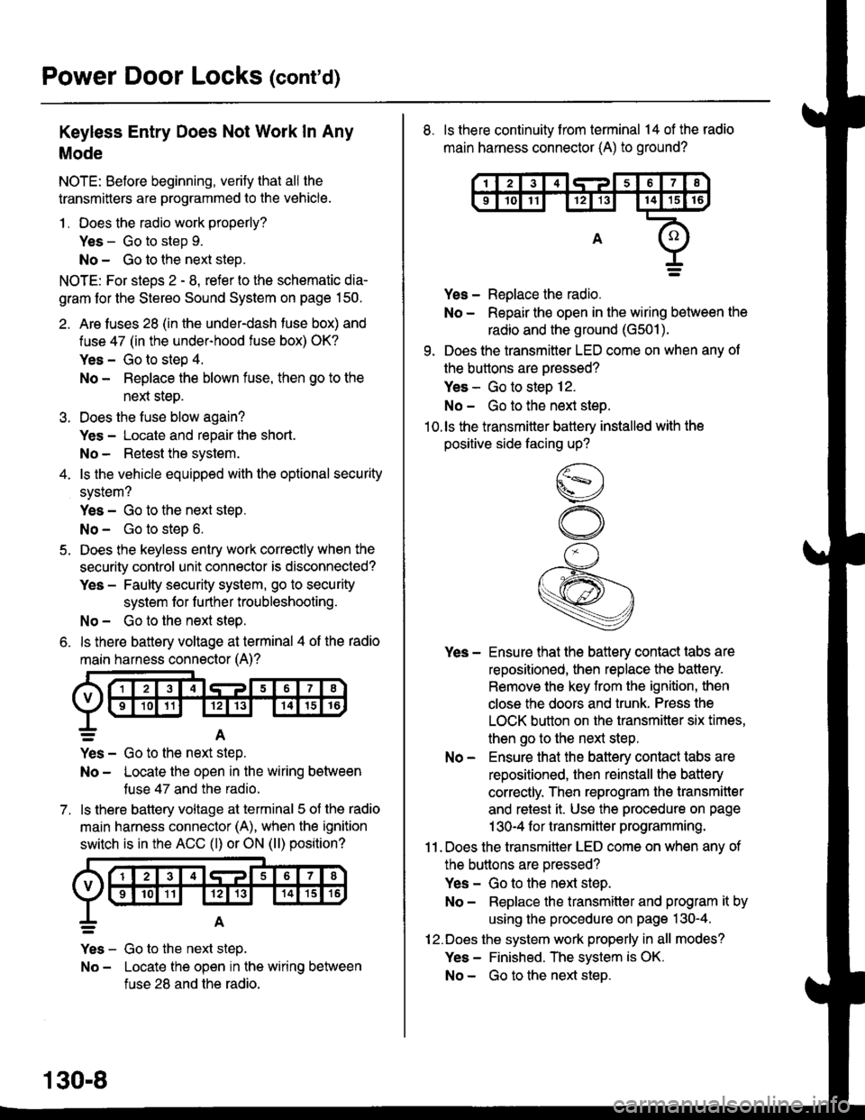
Keyless Entry Does Not Work In Any
Mode
NOTE: Before beginning, verify that all the
transmitters are programmed to the vehicle.
1 . Does the radio work properly?
Yes - Go to step 9.
No - Go to the neld step.
NOTE: For steos 2 - 8. refer to the schematic dia-
gram for the Stereo Sound System on page 150.
2. Are fuses 28 (in the under-dash fuse box) and
fuse 47 (in the under-hood fuse box) OK?
Yes - Go to step 4.
No - Replace the blown fuse, then go to the
nen steo.
3. Does the fuse blow again?
Yes - Locate and repair the short.
No- Retest the system.
4. ls the vehicle equipped with the optional security
system?
Yes - Go to the next steP.
No - Go to steD 6.
5. Does the keyless entry work correctly when the
security control unit connector is disconnected?
Yes - Faulty security system, go to security
system for f urther troubleshooting.
No - Go to the next step.
6. ls there battery voltage at terminal 4 of the radio
main harness connector (A)?
7.
=A
Yes - Go to the nen step.
No - Locate the open in the wiring between
tuse 47 and the radio.
ls there battery voltage at terminal 5 of the radio
main harness connector (A), when the ignition
switch is in the ACC (l) or ON (ll) position?
Yes - Go to the next step.
No - Locate the open in the wiring between
fuse 28 and the radio.
130-8
8. ls there continuity from terminal 14 of the radio
main harness connector (A) to ground?
Yes - Replace the radio.
No - Repair the open in the wiring between the
radio and the ground (G501).
9. Does the transmitter LED come on when any ot
the buttons are oressed?
Yes - Go to steo 12.
No - Go to the next steo.'10.ls the transmitter battery installed with the
positive side facing up?
Yes - Ensure that the battery contact tabs are
repositioned, then replace the battery.
Remove the key from the ignition, then
close the doors and trunk. Press the
LOCK button on the transmitter six times,
then go to the next step.
No - Ensure that the baftery contact tabs are
repositioned, then reinstall the batlery
correctly. Then reprogram the transmitter
and retest it. Use the procedure on page
1 30-4 f or transmitter programming.
11 . Does the transmitter LED come on when any of
the buttons are oressed?
Yes - Go to the next step.
No - Replace the transmitter and program it by
using the procedure on page 130-4.
12.Does the system work properly in all modes?
Yes - Finished. The system is OK.
No - Go to the next steD.