Page 1322 of 2189
Seat Belts
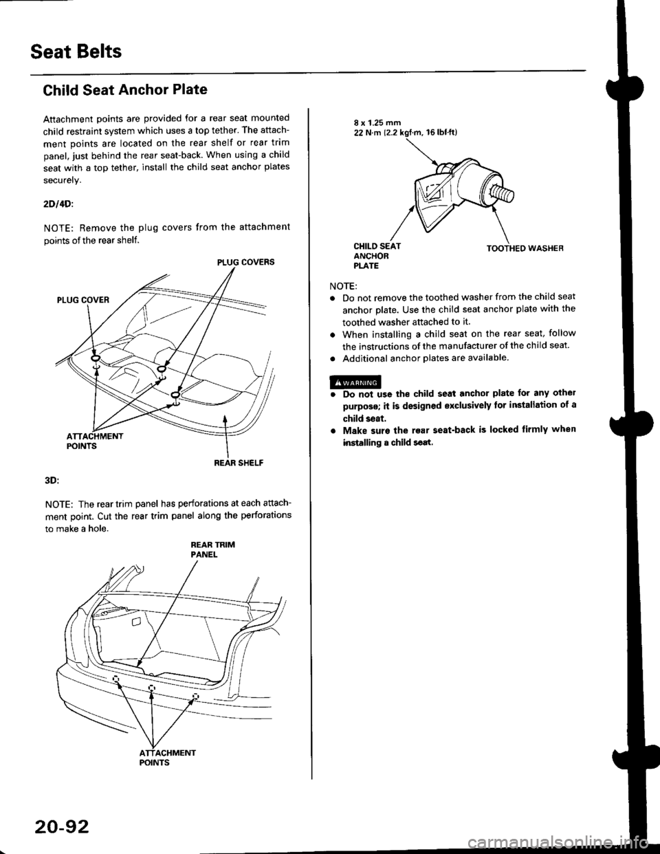
Child Seat Anchor Plate
Attachment points are provided for a rear seat mounted
child restraint system which uses a top tether. The attach-
ment points are located on the rear shelf or rear trim
panel, just behind the rear seat-back. When using a child
seat with a top tether, install the child seat anchor plates
securely.
2Dl4Di
NOTE; Remove the plug covers from the attachment
points of the rear shelf.
3D:
NOTE: The reartrim panel has perforations at each attach-
ment point. Cut the rear trim panel along the perforations
to make a hole.
REAR TRIMPANEL
PLUG COVERS
REAR SHELF
POINTS
20-92
NOTE:
TOOTHED WASHEB
Do not remove the toothed washer from the child seat
anchor plate. Use the child seat anchor plate with the
toothed washer attached to it.
When installing a child seat on the rear seat, follow
the instructions of the manufacturer of the child seat
Additional anchor olates are available.
@r Do not us6 the child seat anchor plate for any othel
purposs; it is designed exclusively tor installation of a
child 3eat.
. Make suro the rear seat-back is locked firmly when
installing 8 child seat.
Page 1331 of 2189
Hatch Spoiler
Removal
NOTE: Take care not to scratch the hatch and body
1. Remove the hatch upper trim (see page 20-63)
2. Remove the nuts, and detach the clip, then lift the
hatch spoiler uP.
a: Nut locations, 4
1 2lbt.ftl _ j/
GROMMET
HIGH MOUNT BRAKELIGHT CONNECTOR
Disconnect the high mount brake light connector and
rear window washer tube, then remove the hatch
spoiler.
------,*;)
4. lf necessary. remove the spoiler trim from the spoiler
frame.
NOTE: The hatch spoiler trim for Canada produced
cars cannot be disassembled.
>: Clip locations
A>,4
>: Scr€w
5. Installation is the reverse of the removal procedure'
NOTEi
. lf necessary, replace any damaged clips.
a Make sure the connector and washer tube are
connected ProPerlY.
20-101
Page 1349 of 2189
Sub-frame
Sub-frame Torque Sequence:
CAUTION: After loos€ning the sub-frame mounting bolts, be sure to replace them with new ones.
BOLTS
10 x 1.25 mm38Nm{3.9kg{.m:
14 x 1.5 mm90 N m (9.1 ks{ m,66 rbf.ft)Replace.
28 tbf.ft)
20-119
Page 1357 of 2189
Front Seat Belt
RemovaUlnstallation
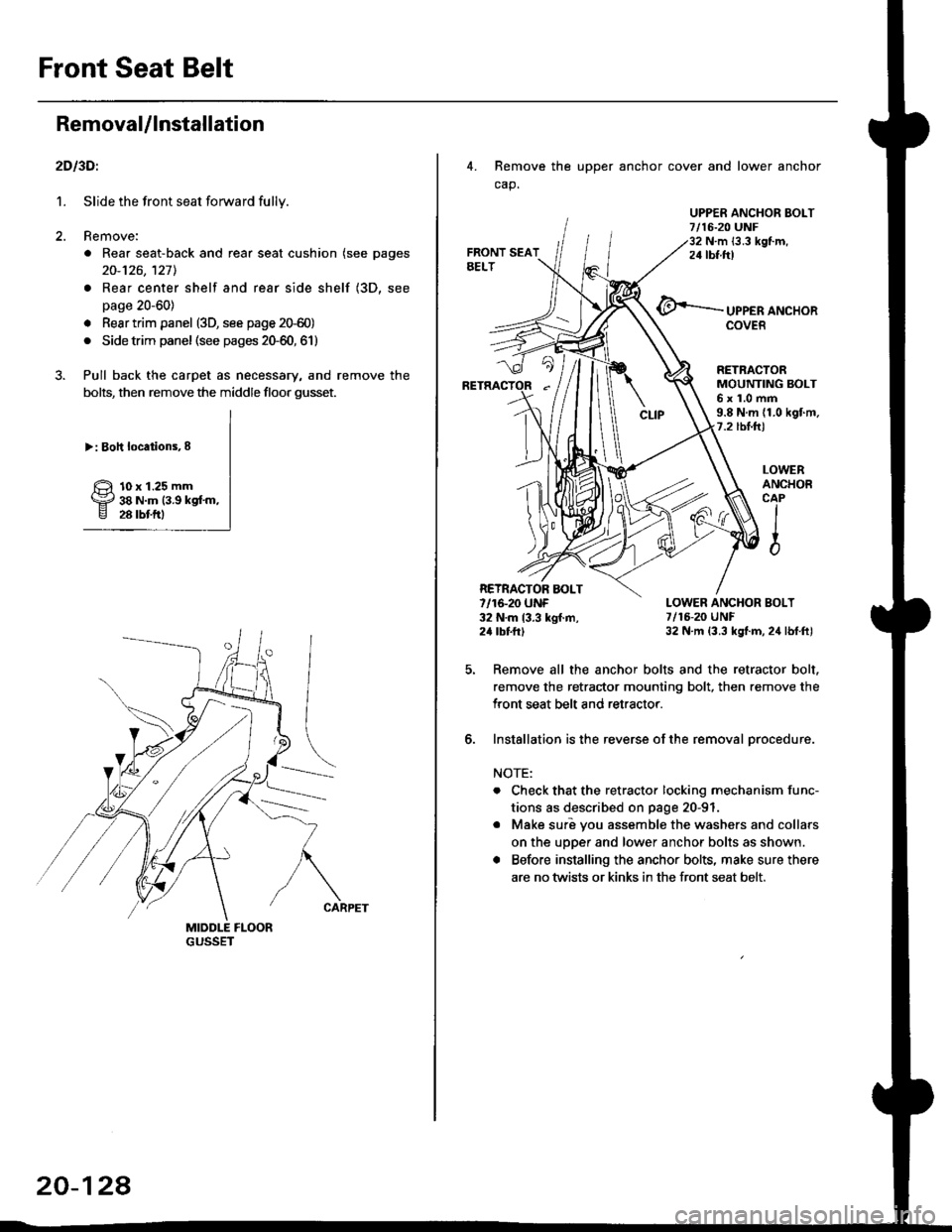
2D l3Dl
1. Slide the front seat forward fully.
2. Remove:
. Rear seat-back and rear seat cushion (see pages
20-126,127l.
. Rear center shelf and rear side shelf (3D, see
page 20-60)
. Resr trim panel (3D, see page 2G60)
. Side trim panel (see pages 20-60, 61)
3. Pull back the carpet as necessary, and remove the
bolts, then remove the middle floor gusset.
>: Boh locations,8
10 x 1.25 mm38 N.m (3.9 kgf'm,28 rbtftl
20-124
4. Remove the upper anchor cover and lower anchor
cap.
UPPER ANCHOR EOLT7/16-20 UNF32 N.m {3.3 kgf.m,24 tbf.ftt
UPPER ANCHORCOVER
LOWERANCHOBCAPIIio
RETRACTORMOUNTING BOLT6x1.0mm9.8 N.m (1.0 kgf.m.7.2 tbl.hl
LOWER ANCHOR BOLT7/16-20 UNF32 N.m (3.3 kgt.m, 24 lbf.ft)
Remove all the anchor bolts and the retractor bolt.
remove the retractor mounting bolt, then remove the
Iront seat belt and retractor.
Installation is the reverse of the removal orocedure.
NOTE:
. Check that the retractor locking mechanism func-
tions as described on page 20-91
o Make suri vou assemble the washers and collars
on the upper and lower anchor bolts as shown.
. Before installing the anchor bolts, make sure there
are no twists or kinks in the front seat belt.
RETRACTOR AOLT7/16-20 UNF32 N.m 13.3 kgf.m,24 tbttrl
6.
Page 1371 of 2189
Seat Belts
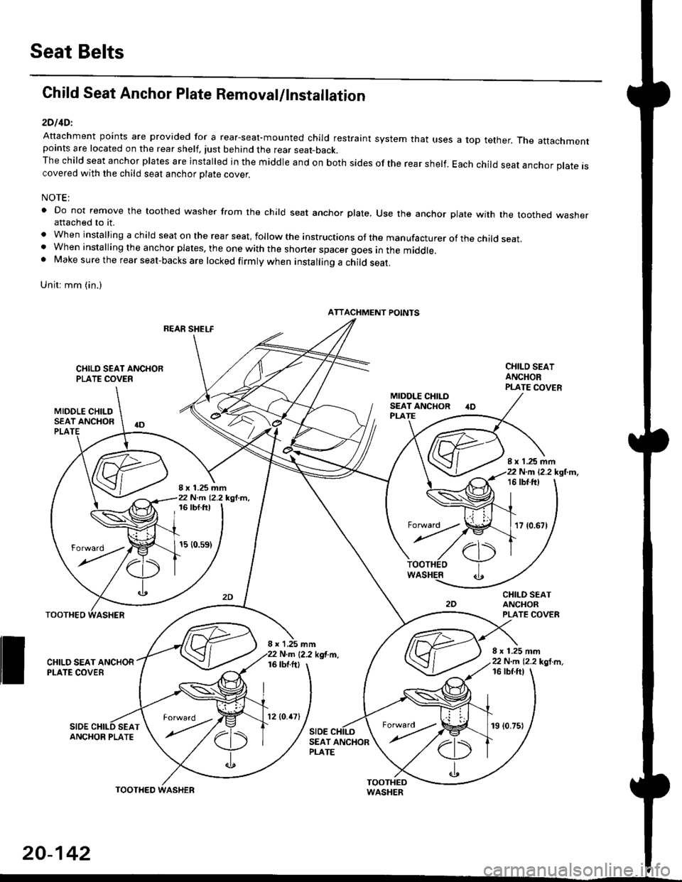
Child Seat Anchor Plate Removal/lnstallation
2DllDl
Attachment points are provided for a rear-seal-mounted child restraint system that usespoints are located on the rear shelf, tust behind the rear seat-back.The child seat anchor plates are installed in the middle and on both sides of the rear shelf.covered with the child seat anchor olate cover.
a top tether. The attachment
Each child seat anchor plate is
NOTE:
' Do not remove the toothed washer from the child seat anchor plate, Use the anchor plate with the toothed washerattached to it.
. When installing a child seat on the rear seat, follow the instructions of the manufacturer of the child seat.. When installing the anchor plates, the one with the shoner spacer goes in the middle.. Make sure the rear seat-backs are locked firmly when installing a child seat.
Unit: mm (in.)
REAR SHELF
CIIILD SEAT ANCHORPLATE COVER
MIDOLE CHILDSEAT ANCHOR
CHILO SEATANCHORPLATE COVER
CHILD SEATANCHORPLATE COVER
8 x 1.25 mm22 N.m 12.2 kgl m,
PLA
8 x 1.25 mm22 N.m 12.2 kgl.m,
I x 1.25 mm22 N.m 12.2 kgl.m,16 tbt.ftt
17 {0.67)
16 tbf.ft)
15 {0.s9)
WASHER
rl)
.t
TOOTHEO
ll ff*,".rd,',i"'"o*
SIDESEAT
I x 1,25 mmN.m {2.2 kgf.m.16 tbtftl
SIDE
16 tbf ftl
ANCHOR PLATESEAT ANCHORPLATE
ATTACHMENT POINTS
torward .
20-142
TOOTHED
12lO.47l19 (0.75)
Page 1372 of 2189
3D:
Attachment points are provided for a rear-seat mounted child restraint system that uses a top tether' The attachment
points are located on the rear trim panel.
The child seat anchor plates are rnstalled in the middle and on both sides of the rear trim panel Each child seat anchor
plale is covered with the child seat anchor plate cover'
NOTE:
. Do not remove the toothed washer from the child seat anchor plate. use the anchor plate with the toothed washer
attached to it.
. when installing a child seat on the rear seat, follow the instructions ol the manufacturer of the child seat'
. Make sure the rear seat-backs are locked firmly when installing a child seat'
gn;1 6rn (in.)
ATTACHMENT POINTS
CHILO SEATANCHOR PLATE
CHILD SEATANCHOB PLATECOVER
8 x 1.25 mm22 N..n (2.2 kgl'm.16 tbfft)
;x?',rff{-*.
20-143
Page 1411 of 2189
Blower Unit
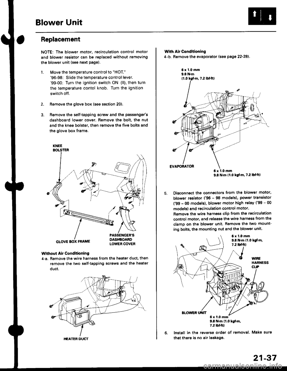
Replacement
NOTE: The blower motor, recirculation control motor
and blower resistor can bs replacsd without rsmoving
th€ blower unit (see neld Page).
1. Move the temperature control to "HOT."
'96-98: Slide the temperature control lever.'99-00: Turn the ignition switch ON (ll), then turn
the temperature contol knob. Turn the ignition
switch off,
Remove the glovs box (ses ssction 20),
R€move ths s6lf-tapping screw and ths passsng6r's
dashboard low€r cover. Removo the bolt, the nut
and the kn€e bolst€r, then remove the fiv€ bolts and
the glove box trame,
Without Air Condhioning
4-a. Remove the wiro harness from the h68t€r duct, then
remove the two self-tapping scrsws and the heatsr
duct.
KNEE
GLOVE BOX FRAME
HEATER DUCT
21-37
Wrth Air Conditioning
4-b. Removo th6 ev8porator (sss pago 22-28).
6x1.0m|n9.8 N'm
6x1.0mm9.8 N'm lt'o tgf'm, t.2 lb{'ttl
Disconnoct the connectors trom th€ blower motor,
blowor r6sistor {'96 - 98 models), power transiator
('99 - 0O modsls), blowor motor high telay ('99 - 00
models) and recirculation control motor.
R€mov€ ths wiro harnoss clip from tho recirculation
control motor, and release the wir6 harnsss from ths
clamo on the blowor unit. Remove the two mount-
ing bolts, tho mounting nut and ths blowor unit'
9.8 .m 11.0 tgfm,1.2 tblfrl
lnstall in ths reverso order of removal. Mako surs
that thsre is no air leaka96.
6x1.0mm9,t N'm 11.0lgi.m,7.2 tbf.fil
Page 1413 of 2189
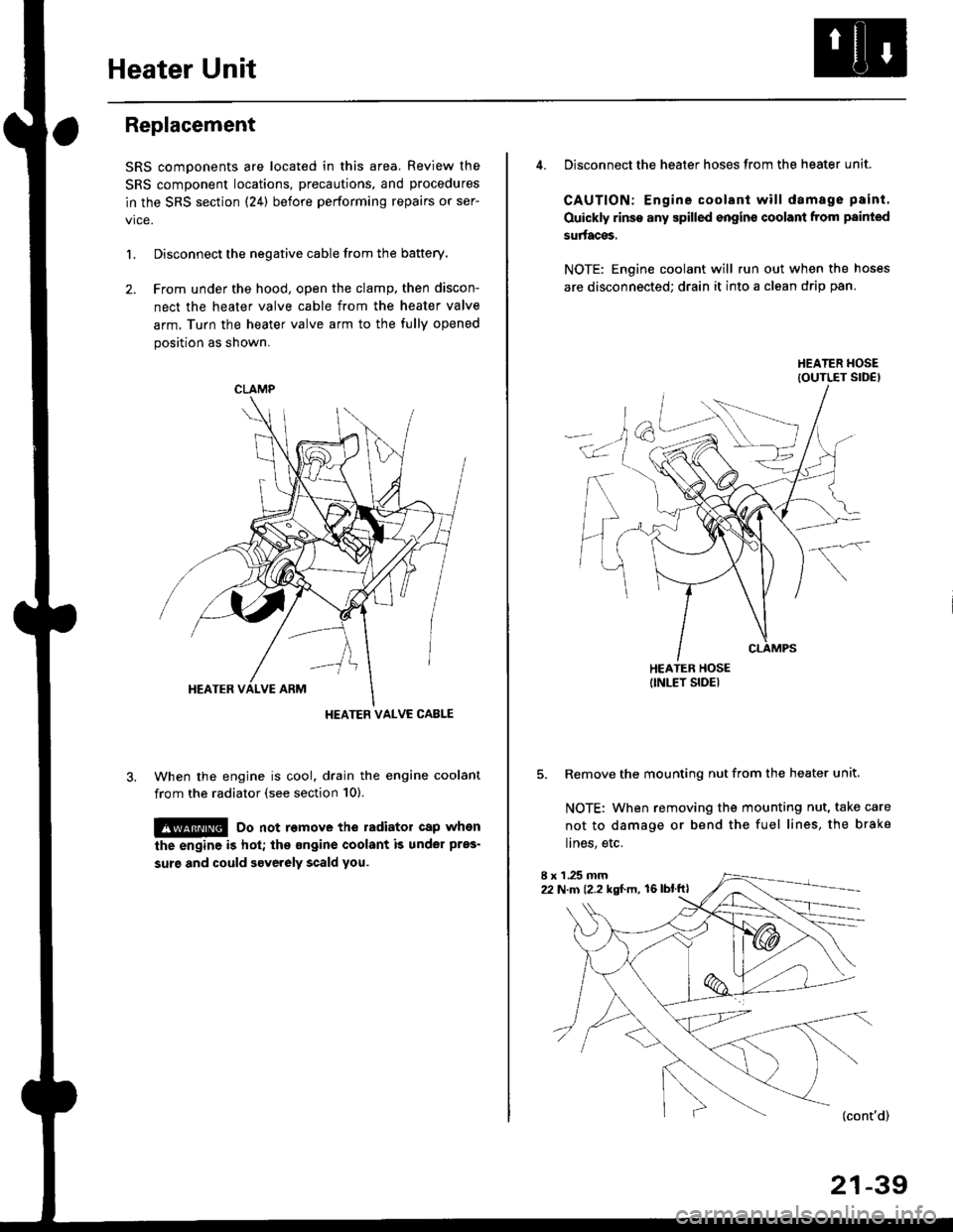
Heater Unit
Replacement
SRS components are located in this area. Review the
SRS component locations, precautions, and procedures
in the SRS section {24} before performing repairs or ser-
L Disconnect the negative cable from the battery.
2. Frcm under the hood, open the clamp, then discon-
nect the heater valve cable from the heater valve
arm. Turn the heater valve arm to the fully opened
position as shown.
When the engine is cool. drain the engine coolant
from the radiator (see section 10).
!@ Do not remove the radiator cap when
the engine is hot; the ongine coolant is under pres'
surg and could severely scald you.
CLAMP
HEATER VALVC CABLE
4. Disconnect the heater hoses from the heater unit.
CAUTION: Engine coolant will damage p8int.
Ouickly rinse any spilled engins coolant from painted
su aces,
NOTE: Engine coolant will run out when the hoses
are disconnected; drain it into a clean drip pan.
5. Remove the mounting nut from the heater unit.
NOTE: When removing the mounting nut, take care
not to damage or bend the fuel lines, the brake
lines, etc.
I x 1 .25 mm22 N.m {2.2 kgl.m, 16lblftl
21-39