Page 975 of 2189
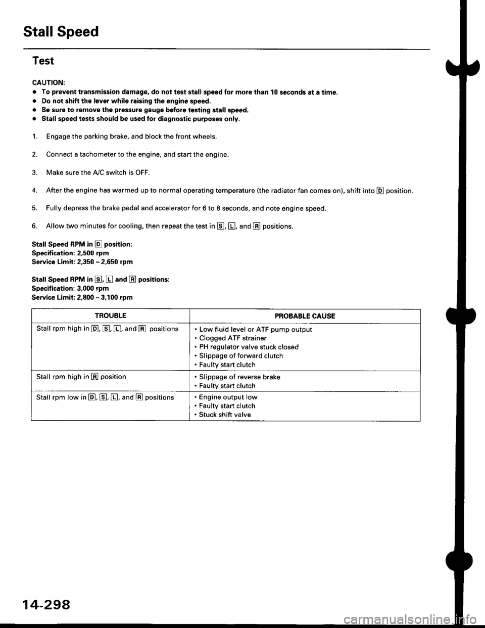
Stall Speed
Test
CAUTION:
. To prevent transmission damage, do not test stall sp€€d for mole than 10 seconds at a time.
. Do not shift the lsver whils raising the engine speod.
. Be sure lo remove the pressure gauge before tosting stall speed.
. Stall speed tssts should be used tor diagnostic purposes only,
1. Engage the parking brake, and block the tront wheels.
2. Connect a tachometer to the engine, and stan the engine.
3. Make sure the A/C switch is OFF.
4. After the engine has warmed up to normal operating temperature (the radiator fan comes on), shift into E position.
5. Fully depress the brake pedal and accelerator for 6 to 8 seconds, and note engine speed,
6. Allow two minutes for cooling, then repeat the test in E, E, and E positions.
Stall Speed BPM in E poshion:
Specification: 2,500 rpm
Servic€ Limit: 2,350 - 2.650 rpm
Stall Speed RPM in E, E and E positions:
Specitication: 3,000 rpm
Service Limit: 2,800 - 3,100 rpm
TROUBLEPROBABLE CAUSE
Stall rpm high in @. p. [, and @ positionsLow fluid level or ATF pump output
Clogged ATF strain€r
PH regulator valve stuck closed
Slippage of forward clutch
Faulty start clutch
Stall rpm high in E position. Slippage of reverse brake. Faulty start clutch
Stall rpm low in E, P, [, and @ positionsEngine output low
Faulty stan clutch
Stuck shift valve
14-294
Page 1059 of 2189
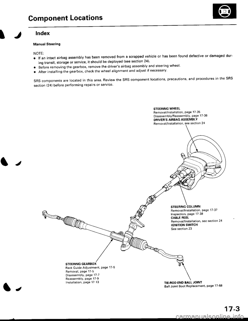
Component Locations
tlndex
Manual Steering
NOTE:
. lf an intact airbag assembly has been removed from a scrapped vehicle or has been found defective or damaged dur-
ing transit. storage or service, it should be deployed (see section 24)'
o Before removing the gearbox, remove the driver's airbag assembly and steering wheel
. After insta lling the gearbox, check the wheel alignmentand adjust if necessary
SRS components are located in this area. Review the SRS component locations, precautions, and procedures in the SRS
section 124) before performing repairs or service'
STEERING WHEELRemoval/lnstallation, Page 17'35
Disassembly/FeassemblY, page 17-36
DRIVER'S AIRBAG ASSEMBLY
Removal/lnstallation, see section 24
STEERING COLUMNRemoval/lnstallation, Page 17-37
Inspection, page 17'38
CABLE REELRemoval/lnstallation, see section 24
IGNTTION SWITCH
See section 23
STEERING GEARBOXRack Guide Adiustment, Page 17-5
Removai, page 17'5Disassembly, Page 17_7Reassembly, page 17_9Installation, page 17 13TIE.ROD END BALL JOINT
Ball Joint Boot Replacement, page 17-68
J
t,
17-3
Page 1060 of 2189
Inspection and Adjustment
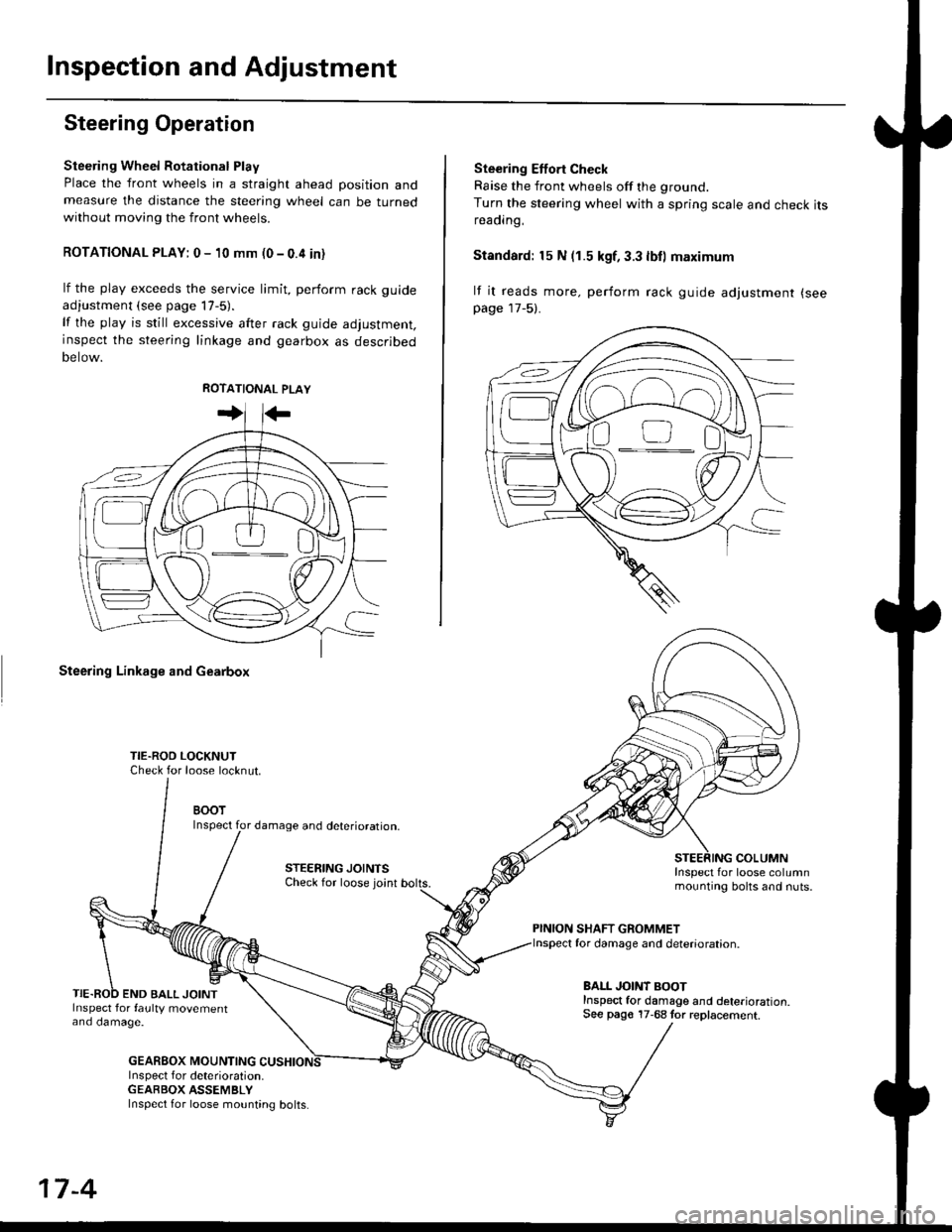
Steering Operation
Steering Wheel Rotational Play
Place the front wheels in a straight ahead position andmeasure the distance the steering wheel can be turnedwithout moving the front wheels.
ROTATIONAL PLAY: 0 - 10 mm (0 - 0.4 in)
lf the play exceeds the service limit, perform rack guide
adjustment (see page lT-5).
lf the play is still excessive after rack guide adjustment,inspect the steering linkage and gearbox as descrjbed
Detow.
Steering Linkage and Gearbox
TIE.ROO LOCKNUTCheck for loose locknut.
BOOTInspect for damage and deterioration.
STEERING JOINTSCheck for loose joint
END BALL JOINTInspect for faulty movementano oamage.
GEABBOX MOUNTINGInspect f or deterioration.GEABBOX ASSEMBLY
Ste€ring Effort Check
Raise the front wheels off the ground.
Turn the steering wheel with a spring scale and check itsreaorng,
Standard: 15 N (1.5 kgf, 3.3 lbll maximum
lf it reads more. perform rack guide adjustment (see
page 17-5).
COLUMNInspect for loose columnmounting bolts and nuts.
PINION SHAFT GROMMETfor damage and deterioration.
BALL JOINT BOOTInspect for damage and deterioration.See pago 17-68 tor replacement.
ao-\---------U
17-4
Inspect for loose mounting bolts.
Page 1071 of 2189
Component Locations
I
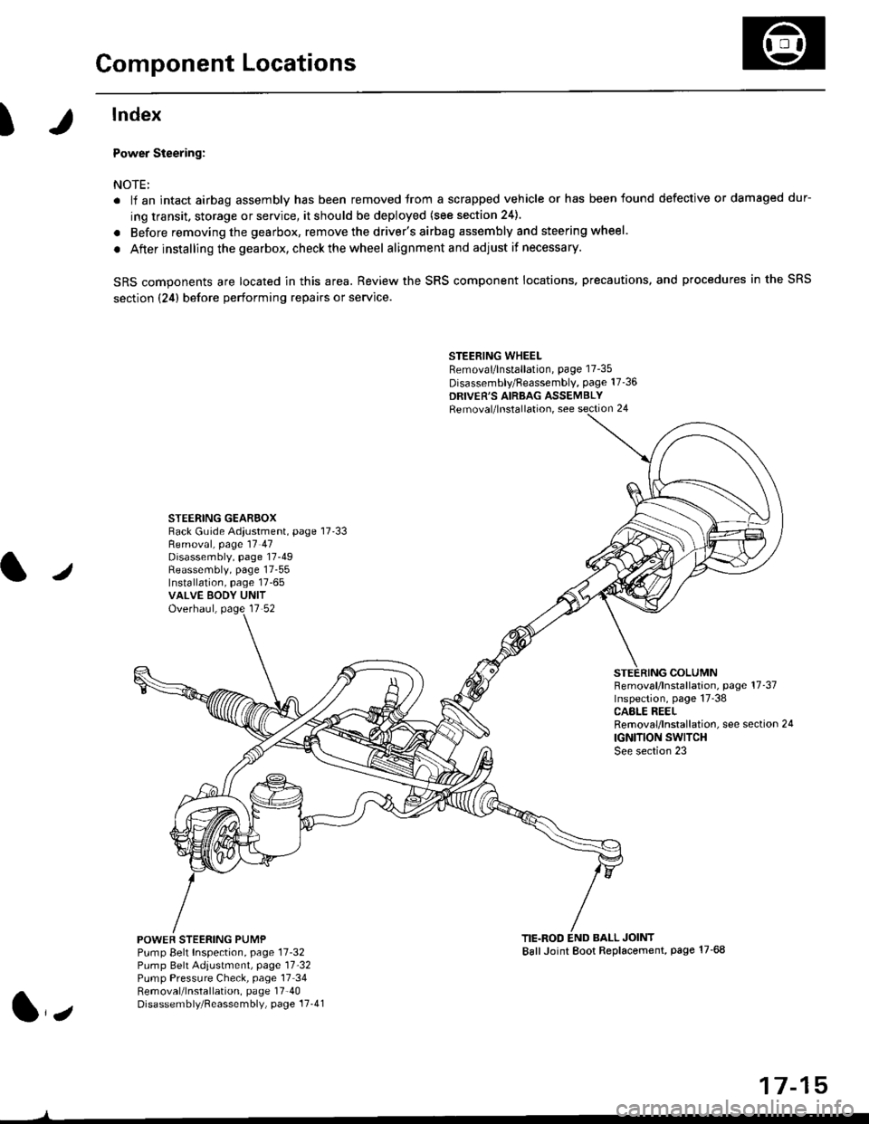
lndex
Power Steering:
NOTE:
. li an intact airbag assembly has been removed trom a scrapped vehicle or has been found defective or damaged dur-
ing transit. storage or service, it should be deployed (see section 24).
. Before removing the gearbox, remove the driver's airbag assembly and steering wheel.
. After installing the gearbox, checkthewheel alignmentand adjust if necessary.
SRS components are located in this area. Review the SRS component locations. precautions, and procedures in the SRS
section {24} before performing repairs or service.
STEERING WHEELRemoval/lnstallation, page 17-35
Disassembly/Feassembly, page 17-36
DRIVER'S AIRBAG ASSEMBLYRemoval/lnstallation, see section 24
STEERING GEAREOXRack Guide Adiustment, page 17'33
/
Removal, page 17 47Disassembly, page 17-49Reassembly, page 17-55Installation, page 17-65VALVE EODY UNITOverhaul, page 17 52
COLUMNFemoval/lnstallation, page 17-37Inspection, page 17-38CASLE REELRemoval/lnstallation, see section 24
IGNITION SWITCHSee section 23
POWEF STEERING PUMPPump Belt Inspection, page 11-32Pump Belt Adiustmenl, page 11'32Pump Pressure Check, page 17 34Removal/lnstallation, page 17'40Disassembly/Reassembly, page 17-41
TIE.ROD END BALL JOINTBallJoint Boot Replacement, page 17-68
1,,
17-15
Page 1086 of 2189
Inspection and Adjustment
Steering Operation
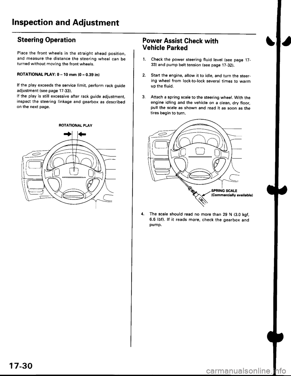
Place the front wheels in the straight ahead position,
and measure the distance the steering wheel can beturned without moving the front wheels.
ROTATIONAL PLAY: 0 - 10 mm l0 - 0.39 inl
lf the play exceeds the service limit. perform rack guide
adjustment (see page 17-33).
lf the play is still excessive after rack guide adjustment.inspect the steering linkage and gearbox as describedon the nel(t pag€.
ROTATIONAL PLAY
17-30
Power Assist Gheck with
Vehicle Parked
1. Check the power steering fluid level (see page 17-33) and pump belt tension (see page 17-32).
2. Start the engine, allow it to idle. and turn the steer-ing wheel from lock-tolock several times to warm
up the fluid.
3. Attach a spring scale to the steering wheel. With theengine idling and the vehicle on a clean, dry floor,pull the scale as shown and read it as soon as thetires begin to turn.
The scale should read no more than 29 N (3.0 kgf.
6.6 lbf). lf it reads more, check the gearbox andpump,
D0
Page 1131 of 2189
Wheel/Hub Inspection
\
Bearing End Play
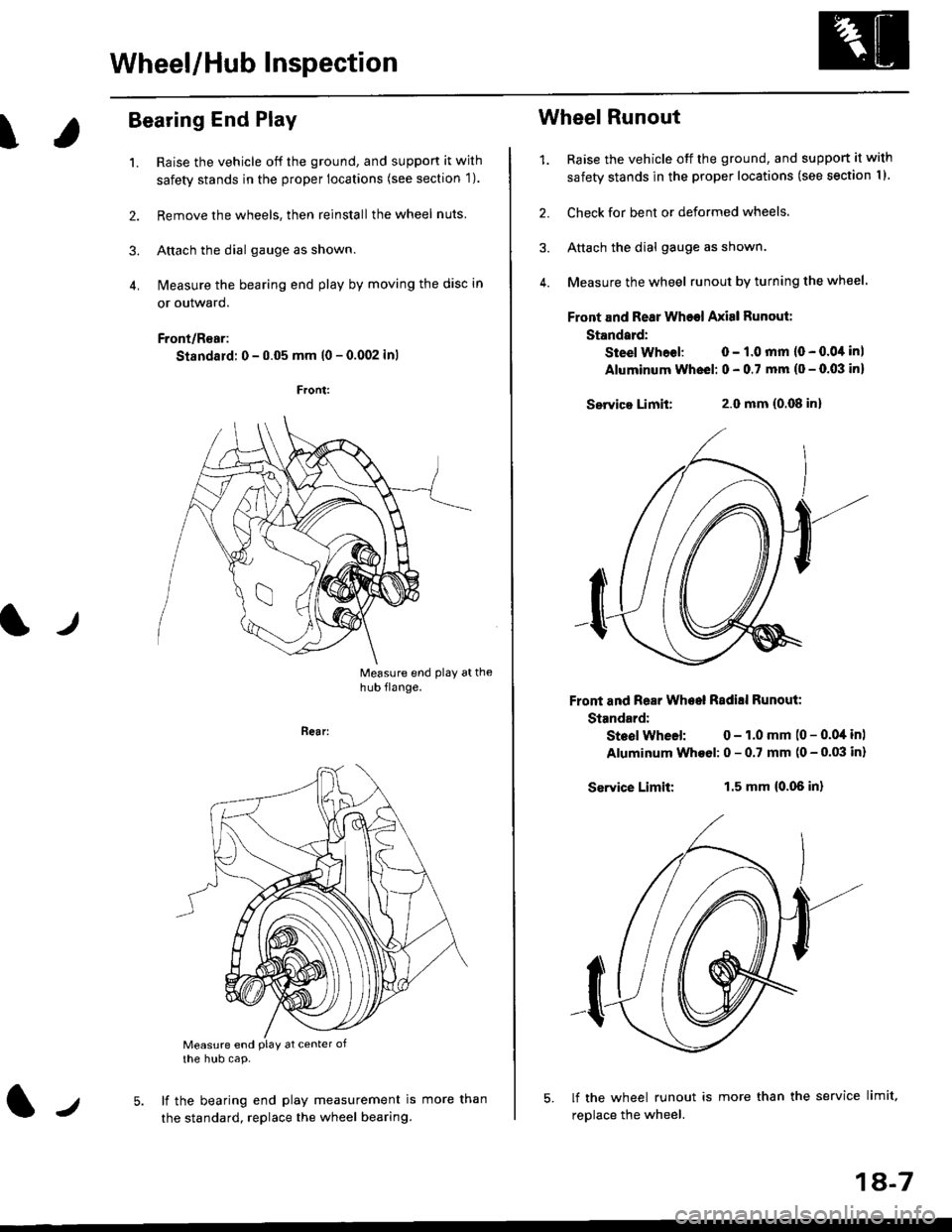
1. Raise the vehicle off the ground, and suppon it wjth
safety stands in the proper locations (see section 1).
2. Remove the wheels, then reinstallthe wheel nuts
3. Attach the dial gauge as shown.
4. N4easure the bearing end play by moving the disc in
or outward.
Front/R€ar:
Standard: 0 - 0.05 mm l0 - 0.002 inl
Measure end play athub flange.
t./
Bear:
Measure end PlaY at center ofthe hub cap.
lf the bearing end play measurement is
the standard, replace the wheel bearing.lJmore than
1A-7
Wheel Runout
1. Raise the vehicle off the ground, and support it with
safety stands in the proper locations (see section I I
2. Check for bent or deformed wheels.
3. Attach the dial gauge as shown.
4. Measure the wheel runout by turning the wheel.
Front and Rear Wheel Axisl Runout:
Standard:
Steel Whoel: 0 - 1.0 mm (0 - 0.0,1 inl
Aluminum Wheel: 0 - 0.7 mm (o - 0.03 in)
Servica Limit:2.0 mm (0.08 inl
Front and Rear Wheel Radill Runout:
Standard:
Steol Wheel: 0 - 1.0 mm (0 - 0.04 in)
Aluminum Wheol: 0 - 0.7 mm (0 - 0.03 in)
Service Limit:1.5 mm {0.06 in}
lf the wheel runout is more than the service limit,
replace the wheel.
Page 1162 of 2189
Front Brake Pads
Inspection and Replacement
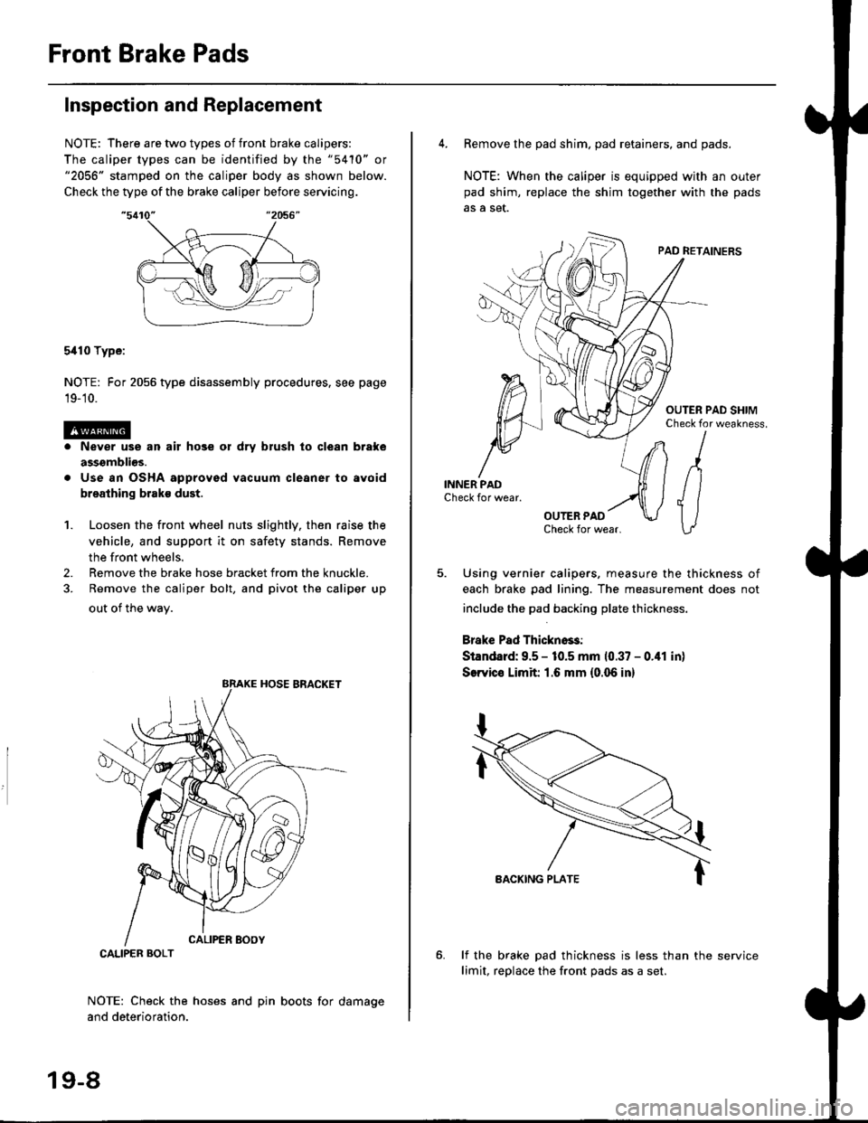
NOTE: There are two types of front brake calipers:
The caliper types can be identified by the "5410" or"2056" stamped on the caliper body as shown below.
Check the type of the brake caliper before servicing.
5i110 Type:
NOTE: For 2056 type disassembly procedures. see page
19-'10.
Never use an air hose or dry brush lo clean brake
assgmblios.
Use an OSHA approved vacuum cleaner to avoid
breathing brake dust.
Loosen the front wheel nuts slightly, then raise the
vehicle, and support it on safety stands. Remove
the front wheels.
Remove the brake hose bracket from the knuckle.
Remove the caliper bolt, and pivot the caliper up
out of the wav.
1.
2.
NOTE: Check the hoses and pin boots for damage
and deterioration.
CALIPER BOLT
19-8
4. Remove the pad shim. pad retainers, and pads.
NOTE: When the caliper is equipped with an outer
pad shim, replace the shim together with the pads
5. Using vernier calipers, measure the thickness of
each brake pad lining. The measurement does not
include the pad backing plate thickness.
Brake Pad Thickno$:
Standard: 9.5 - 10.5 mm 10.37 - 0.41 in)
SerYico Limit 1.6 mm {0.06 in}
lf the brake pad thickness is less than the service
limit, replace the front Dads as a set.
Page 1164 of 2189
Front Brake Pads
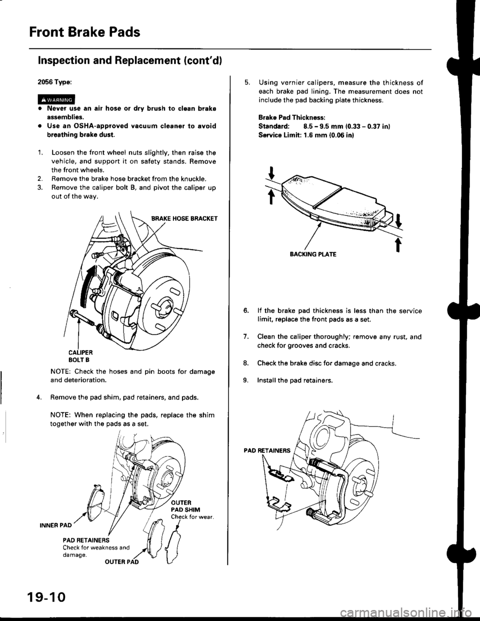
2056 Type:
@. Never use an air hose or dry brush to clgan brake
assemblies.
. Use an OsHA-approved vacuum cleanor lo avoid
breathing broke dust.
Inspection and Replacement (cont'dl
1. Loosen the front wheel nuts slightly. then raise the
vehicle, and support it on safety stands. Remove
the front wheels.
2. Remove the brake hose bracket from the knuckle.
3. Remove the caliper bolt B, and pivot the caliper up
out of the wav,
EOLT B
NOTE: Check the hoses and pin boots for damage
and deterioration.
Remove the pad shim, pad retainers, and pads.
NOTE: When replacing the pads, replac€ the shim
together with the pads as a set,
OUTERPAD SHIMCheck for wear.
INNER PAD
PAO RETAINERSCheck for weakness anddamage,OUTER PAD
19-10
5. Using vernier calipers. measure the thickness of
each brake pad lining. The measurement does not
include the pad backing plate thickness.
Brake Pad Thicknsss:
Standard; 8.5 - 9.5 mm 10.33 - 0.37 in)
Servica Limh: 1.6 mm {0.06 in}
lf the brake pad thickness is less than the service
limit, replace the front pads as a set,
Clean the caliper thoroughly; remove any rust. and
check for grooves and cracks.
Check the brake disc for damage and cracks,
Install the pad retainers.
7.
8.
9.