1998 HONDA CIVIC ABS
[x] Cancel search: ABSPage 1228 of 2189
\il
Modulator Unit
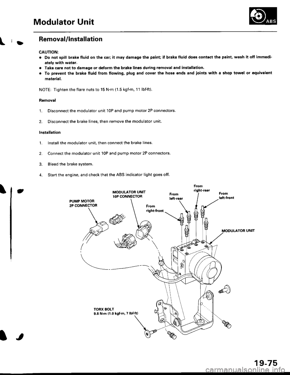
RemovaUlnstallation
CAUTION:
. Do not spill brake tluid on the car; it may damage the paint; it brako lluid does contact the paint, wash it off immedi-
ately with wator.
a Take care not to damage or delorm the brake lin€s during removal and installation.
. To prevent the brake tluid from tlowing, plug and cover the hose €nds and ioints with a shop tow6l or equivalent
mat€rial.
NOTE| Tightentheflare nutsto 15 N.m (1.5 kgnm. l1 lbf.ft).
Removal
'1. Disconnect the modulator unit 10P and Dump motor 2P connectors.
2. Disconnect the brake lines, then remove the modulator unit.
Installaiion
1. Install the modulator unit. then connect the brake lines.
2. Connect the modulator unit 10P and oumD motor 2P connectors.
3. Bleed the brake system.
4. Start the engine, and check that the ABS indicator light goes off.
Fomright-1461
PUMP MOTOR2P CONNECTOR
J
-R
/2e'
t'
TOR UNIT
tt
19-75
Page 1229 of 2189
ABS Control Unit
Pulsers/Wheel
Sensors
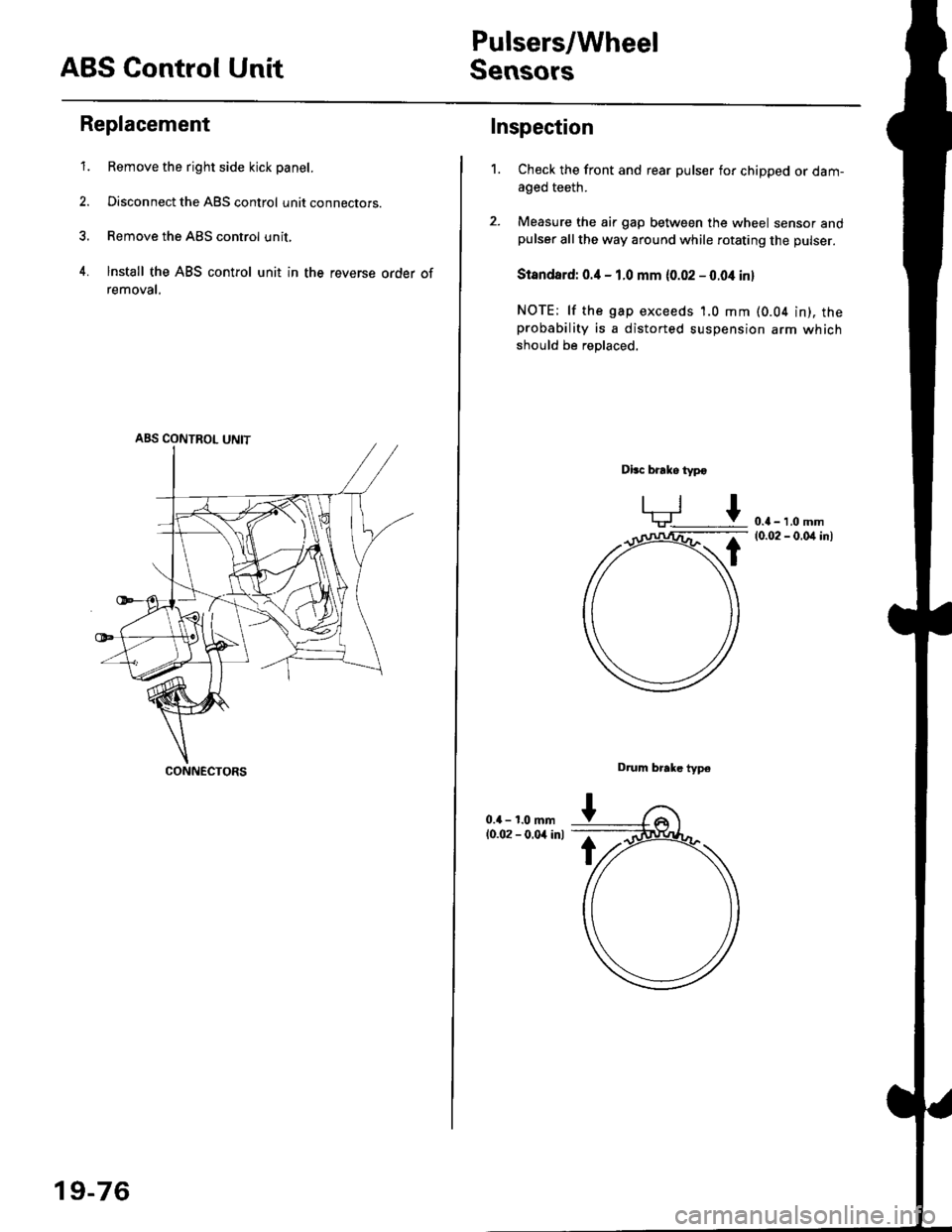
Replacement
1. Remove the right side kick panel.
2. Disconnect the ABS control unit connecrors.
3. Remove the ABS control unit,
4. lnstall the ABS control unit in the reverse order of
removal,
CONNECTORS
19-76
Inspection
Check the front and rear pulser for chipped or dam-aged teeth.
Measure the air gap between the wheel sensor andpulser all the way around while rotating the pulser.
Slandard: 0.4 - 1.0 mm (0.02 - 0.04 in,
NOTE; lf the gap exceeds 1.0 mm (0.04 in), theprobability is a distorted suspension arm which
should be replaced.
Dbc brake typo
0.{ - 1.0 mm(0.02 - 0.04 in)
Drum brake typ6
1.
Page 1324 of 2189

Front Bumper
Replacement
CAUTION: Put on glov$ to protect your hands.
NOTE:
. An assistant is helpful when removing the front bumper.
. Take care not to scratch the front bumDer and bodv.
FRONT BUMPERSIDE SNFFENER
lnstallation is the reverse of the removal orocedure.
NOTE:
. Make sure the front bumper engages the front
bumper side stiffener on each side securely.
. lf necessary, adjust the front bumper side stiffener
to obtain the proper gap.
>: golt, screw locationsa>,2B>,2>: Cliplocations, 7
iAerr:ore. A lm
L.'* fl'T;Ll'
o'n' -'
\€5>_ JIc>,4 ,D>,4
| -.6a 8 x 't.25 mm l,Rt o x 1.0 mm
l(Dl[m 22N.n'.t2.2kstnf'. j(Qll@ s.e N.m rr.o rsf.m,t'KJ) 16 tbf.ft, |. -ll 7.2 tbf.hJ
ABSORBER
FRONT EUMPERBEAM
FRONT BUMPERSIDE STIFFENER
FRONT BUMPER BEAM
:l
I ir
\
20-94
Page 1416 of 2189
Heater Control Panel
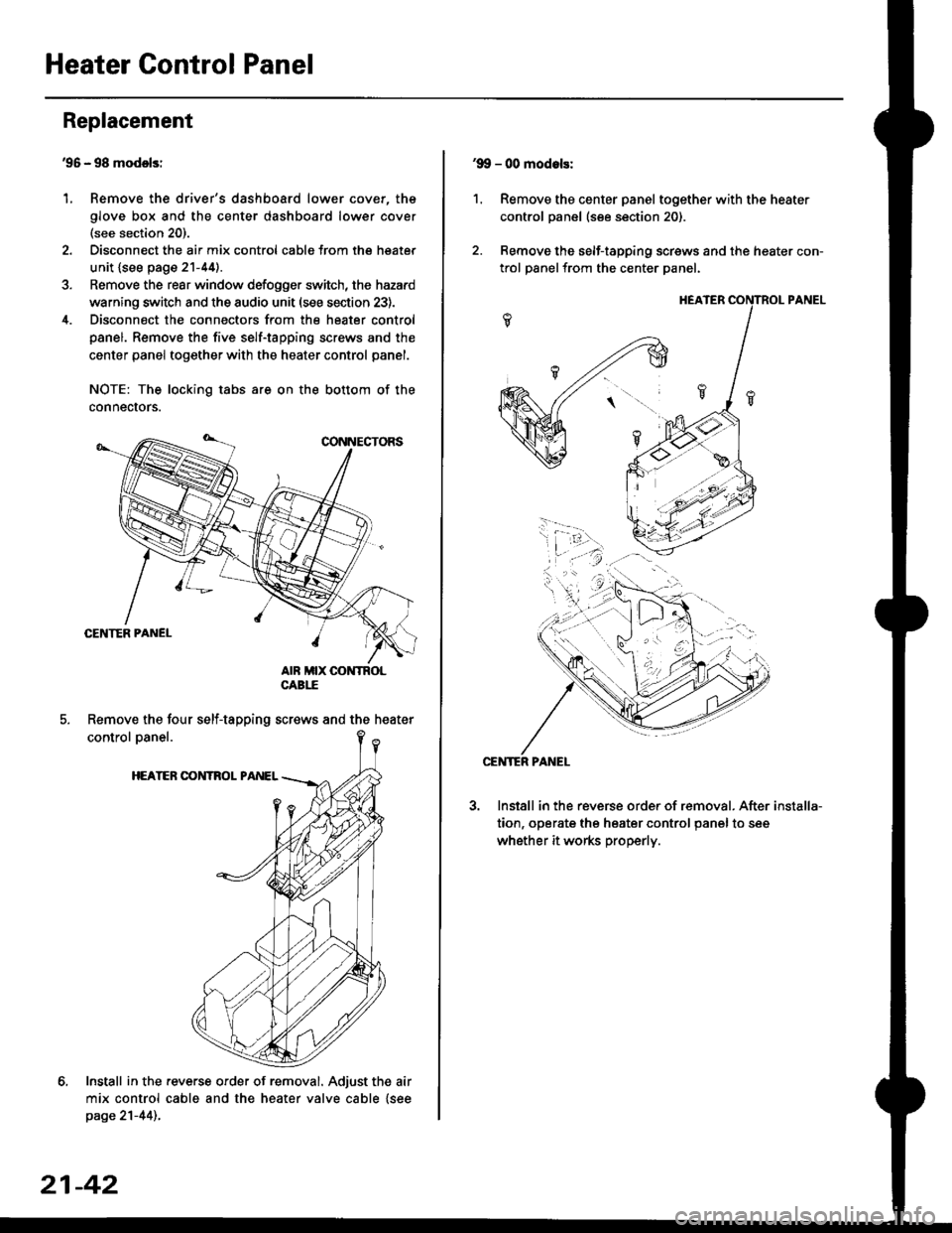
'95 - 98 modolsi
Remove the driver's dashboard lower cover, the
glove box and the center dashboard lower cover(see section 20).
Disconnect the air mix control cabls from the heater
unit {see page 21-44).
Remove the rear window defogger switch, the hazard
warning switch and the audio unit (see section 23).
Disconnect the connectors from the heater control
panel. Remove the five self-tapping screws and the
center panel together with the heater control panel.
NOTE: The locking tabs are on the bottom of the
connecrors.
Install in the .everse order of removal. Adjust the air
mix control cable and the heater valve cable {seepage 21-44)..
Replacement
1.
Remove the four self-tapping screws and the heater
21-42
1.
'9!, - 00 modols:
Remove the center panel together with the heater
control panel (see section 20).
Remove the self-tapping screws and the heater con-
trol panelfrom the center Danel.
Install in the reverse order of removal. After
tion, operate the heater control panel to see
whether it works properly.
installa-
Page 1429 of 2189
Description
Outline
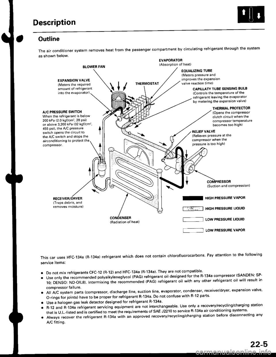
The air conditioner system removes heat from the passenger compartment by circulating refrigerant through the system
as shown below.
BLOWER FAN
EVAPORATOR(Absorption of heati
EOUALIZING TUBE(Meters pressure andimproves the expansionvalve reaction time)
into the evaporator)CAPILLATY TUBE SENSING BULB
lControls the temPerature of the
ref rigerant leaving the evaporator
by metering the expansion valve)
/\
THERMOSTAT
A/C PRESSURE SWITCH
When the refrigerant is below
200 kPa (2.0 kgtcm'�,28 Psi)or above 3,200 kPa 132 kgflcm',
455 psi), the Ay'C pressure
switch opens the circuit to
the A,/C switch and stops the
EXPANSION VALVE(Meters the requiredamount of refrigerant
airconditioning to Protect the
compressor.
RECEIVER/DRYER(Traps debris, andremoves morsturel
THERMAL PROTECTOR
{Opens the comPressorclutch circuit when the
compressor temPeraturebecomes too high)
RELIEF VALVE(Relieves pressure at the
compressor when thepressure is too high)
(Radiation of heat)
I
f-r-�-; I
(Suction and comPression,
HIGH PRESSURE VAPOR
HtGH PRESSUBE LIOUID
LOW PRESSURE LIOUID
This car uses HFC-134a (R-134a) refrigerant which does not contain chlorofluorocarbons Pay attention to the following
service items:
. Do not mix refrigerants CFC-12 (R-12) and HFC-134a (R-134a)' They are not compatible'
. Useonlythe recommended polyalkyieneglycol (PAG) refrigerant oil designedforthe R-134a compressor (SANDEN: SP-
10; DENSO: ND_OIL8). Intermixing ihe re-commended (pAG) refrigerant oil with any other refrigerant oil will result in
compressor failure.
. All A,,ic system parts {compressor, discharge line, suction line, evaporator, condenser, receiver/dryer, expansion valve'
O-rings for joints) have to be proper for refrigerant R- 134a Do not confuse with R-l2 parts'
. Use a halogen gas leak detector designed for refrigerant R-134a
. R-12 and R-134a refrigerant servacing equipment are not interchangeable. Use only a recovery/recycling/charging station
that is u,L.-listed and is certified to meet the requirements of sAE J2210 to service R-134a air conditioning systems'
. Always recover the refrigerant R-134a with an approved recovery/recycling/charging station before disconnecting any
A,/C fitting.
S]
22-5
Page 1446 of 2189
A/C Service Tips and Precautions
The air conditioner system uses HFC-134a (R-134a) refrigerant and polyalkyleneglycol (PAG) refrigerant oil*, which are not
compatible with CFC-12 (R-12) refrigerant and mineral oil. Do not use R-12 refrigerant or mineral oil in this system, and do
not attempt to use R-12 servicing equipmenU damage to the air conditioner system or your servicing equipment will result.*Sanden SP-10:
. P/N 38897 - P13 - A0lAH: 120 ml 14ll.oz, 4.2lmp.oz)
. P/N 38899 - P13 - A0l | 40 mf 11 1/3ll.oz,1.4 lmp'oz)
Use only service equipment that is U.L. listed and is certified to meet the requirements of SAE J2210 to remove R 134a
from the air conditioner system.
CAUTION: Exposure to air conditioner ref;ige;ant and lubricant vapol or mist can irritate syes, nose and throat, Avoid
breathing the air conditioner refrigerant and lubricant vapor or misl.
lf accidental system discharge occurs, ventilate work area before resuming service.
R-'134a service equipment or vehicle air conditioner systems should not be pressure tested or leak tested with compressed
ai.
!@@ some mixtures of air and R-t3ila have been shown to be combustible at elevated pressures and can result
in tire or explosion causing iniury or property damage. Never use compressed air lo pressure tesl R-134a service equip-
ment or vehicle 8ir conditioner systoms.
Additional health and safety information may be obtained from the refrigerant and Iubricant manufacturers.
L Always disconnect the negative cable from the battery whenever replacing air conditioning pans.
2. Keep moisture and dust out of the system. When disconnecting any lines, plug or cap the fittings immediately; don't
remove the caps or plugs until just before you reconnect each line.
3. Before connecting any hose or line, apply a few drops of refrigerant oilto the O-ring.
4, When tightening o. loosening a fitting, use a second wrench to support the matching fitting.
5. When discharging the system, use a R-134a refrigerant recovery/recycling/charging station; don't release refrigerant
into the atmosphere,
6. Add refrigerant oil after replacing the following parts:
NOTE:
. To avoid contamination, do not return the oil to the container once dispensed, and never mix it with other refriger-
ant oils.
. lmmediately after using the oil, replace the cap on the container, and seal it to avoid moisture absorption.
. Do not spill the refrigerant oil on the vehicle; it may damage the paint; if the refrigerant oil contacts the paint, wash
it off immediately.
Condenser .......2o ml (2/3 fl.oz, 0.7 lmp.ozl
Evaporator .,.,.,. i[5 m{ 11 213 tl.oz,1,6lmp.ozl
Line or hose ..... 10 mf (1/3 fl.oz, 0.4 lmp.ozl
Receiver/Dryer 10 m{ (1/3 fl.oz,0.'l lmp.ozl
Leakage repair 25 m{ (5/6 fl.oz, 0.9 lmp.ozl
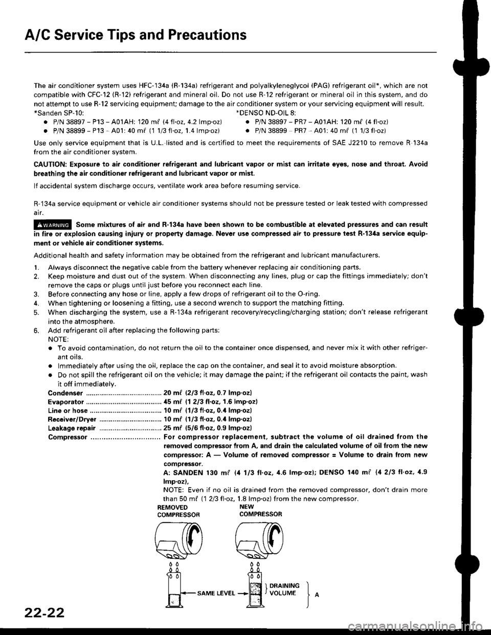
Comptessor ... For compressor replacement. subtract the volume of oil drained trom the
removed compressor from A, and drain the calculated volume of oilfrom the new
compressor: A - Volume of removed compressor: Volume to drain from new
comoressor.
A: SANDEN 130 mf l/t 113 ll.oz, 4.6 lmp'ozl; DENSO 140 mf {4 213 ll'oz, 1.9
lmp.oz),
NOTE: Even if no oil is drained from the removed compressor, don't drain more
than S0 m{ 112Ell.oz,1.8 lmp.oz) fromthe new compressor.
REMOVED NEW
COMPRESSORCOMPRESSOR
*DENSO ND-OlL 8l
. P/N 38897 - PR7 - A01AH: 120 ml (4 fl.oz)
. P/N 38899 PR7-A01:40mf (1 1/3fl'oz)
rereW W0000
22-22
-0_!- -0_a
Tol l00l
| | lffi 1 onrrrutrc I
fi+-sAME
LEvEr...+jEf,voLUME
J
^
Page 1455 of 2189
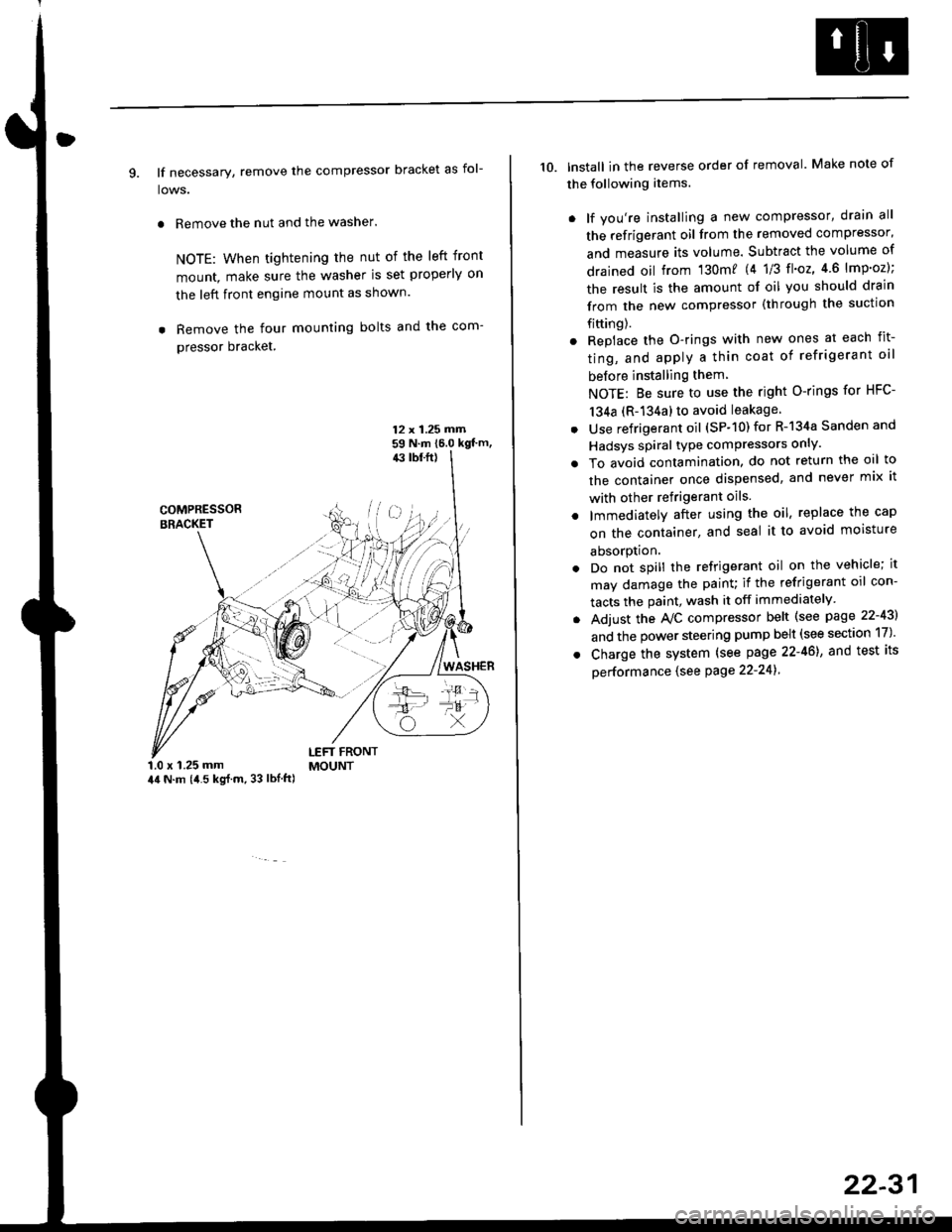
9. lf necessary, remove the compressor bracket as fol-
lows.
. Remove the nut and the washer.
NOTE: When tightening the nut of the left front
mount, make sure the washer is set properly on
the left front engine mount as shown.
. Remove the four mounting bolts and the com-
pressor bracket.
12 x 1.25 rrirn59 N.m 16.0 kgt'm,43 tbf.ft)
COMPRESSORBRACKET
WASHER
1.0 x 1.25 mm44 N.m (i1.5 kg{.m, 33 lbl.ft)
LEFT FRONTMOUNT
10. lnstall in the reverse order of removal. Make note of
the following items.
. lf you're installing a new compressor, drain all
the refrigerant oil from the removed compressor,
and measure its volume. Subtract the volume of
drained oil from '130m? 14 1/3 tl'o2,4 6 lmp'oz);
the result is the amount of oil you should drain
from the new compressor (through the suction
fifting).
. Replace the O-rings with new ones at each fit-
ting, and apply a thin coat of refrigerant oil
before installing them
NOTE: Be sure to use the right O-rings for HFC-
134a (R-134a) to avoid leakage
. Use refrigerant oil (SP-10) for R-134a Sanden and
Hadsys spiral type compressors only'
o To avoid contamination, do not return the oil to
the container once dispensed, and never mix it
with other refrigerant oils.
. lmmediatelY after using the oil, replace the cap
on the container, and seal it to avoid moisture
absorption.
. Do not spill the refrigerant oil on the vehicle; it
may damage the painu if the refrigerant oil con-
tacts the paint, wash it off immediately
. Adjust the Ay'C compressor belt (see page 22-43)
and the power steering pump belt (see section 17)'
. Charge the system (see page 22-46), and test its
oerformance (see Page 22-241
22-31
Page 1460 of 2189
Compressor (SANDENI
Thermal Protestor Replacement
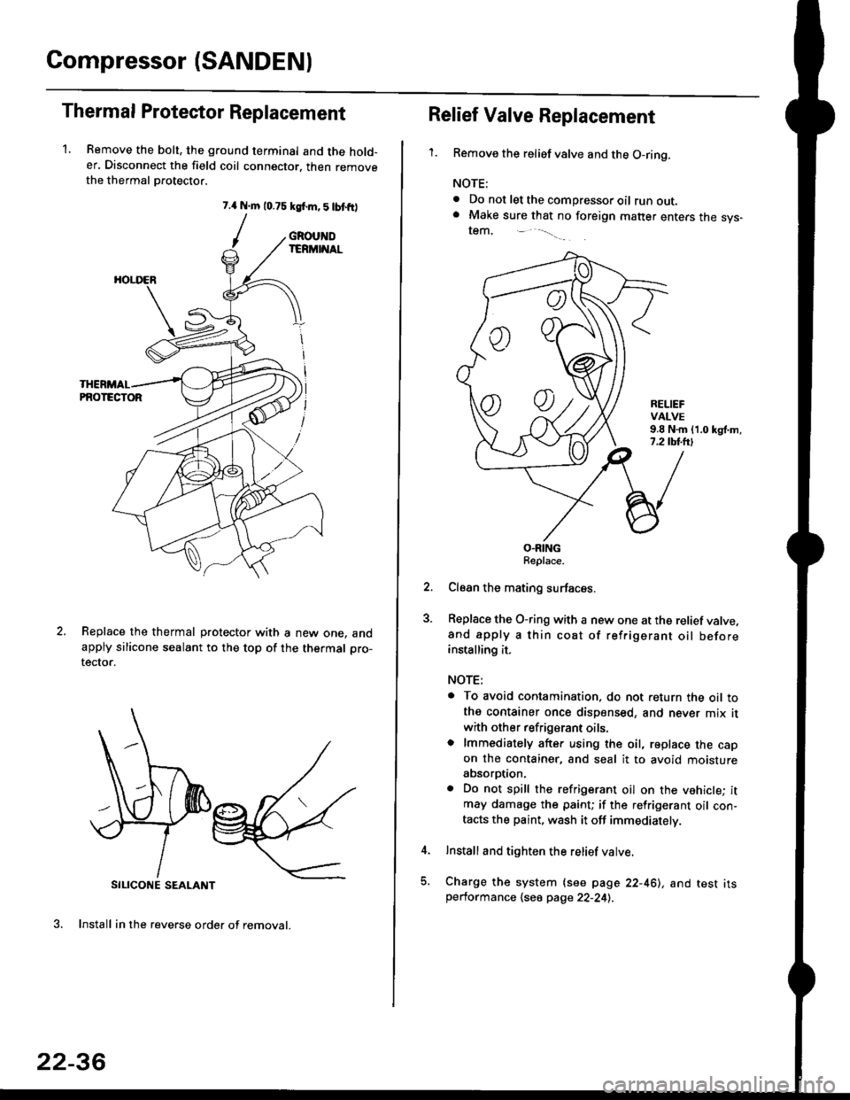
1. Remove the bolt, the ground terminal and the hold-er. Disconnect the field coil connector. then removethe thermal Drotector.
7.{ N.m 10.75 ksf.m,5lbtfr)
/
SILICONE SEALANT
3. Install in the reverse order of removal.
GROUNDIERMINAL
HOI.I'ER
PNOTECTOR
Replace the thermal protector with a new one. andapply silicone sealant to the top of the thermal pro-
tector.
22-36
oo
Relief Valve Replacement
'1.Remove the relief valve and the O-ring.
NOTE:
. Do not let the compressor oil runout.. Make sure that no foreign matter enters the sys-tem,
RELIEFVALVE9.8 N.m {1.0 kgl.m,7.2 tbl.lrl
O.RINGReplace.
Clean the mating surfaces.
Replace the O-ring with a new one at the relief valve.and apply a thin coat of refrigerant oil beforeinstalling it.
NOTE:
. To avoid contamination. do not return the oil tothe container once dispensed, and never mix it
with other refrigerant oils.o lmmediately after using the oil, replace the capon the container, and seal it to avoid moistureabsorption.
. Do not spill the refrigerant oil on the vehicle; itmay damage the paint; if the refrigerant oil con-tacts the paint, wash it off immediately.
Install and tighten the relief valve.
Charge the system {see page 22-461, and test itsperformance 1se6 page 22-241.