Page 1103 of 2189
Steering Gearbox
)
Removal
NOTE: Using solvent and a brush, wash any oil and dirt
off the valve body unit its lines. and the end if the gear-
box. Blow dry with comPressed air.
1. Drain the power steering fluid as described on page
2. Raise the front of vehicle, and support it on safety
stands in the proper locations (see section 11.
3, Remove the front wheels.
4. Remove the driver's airbag assembly, and steering
wheel (see page 17-35)
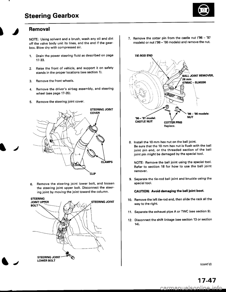
5. Bemove the steering joint cover.
6. Remove the steering joint lower bolt, and loosen
the steering joint upper bolt. Disconnect the steer-
ing joint by moving the ioint toward the column
tJ
17-47
TIE.ROD END
7. Remove the cotter pin from the castle nut {'96 -'97
models) or nut ('98 - '00 modslsl and remove the nut.
BALL JOINT REMOVER.28 mm07MAC - SLqI2|X)
'98 - '00 mod.b:NUT
8.
COTTER PINSRepl6ce.
lnstall the t0 mm hex nut on the ball joint.
Be sure that the 10 mm hex nut is flush with the ball
joint pin end, or the threaded section of the ball
joint pin might be damaged by the special tool.
NOTE: Remove the ball joint using the special tool.
Refer to section 18 for how to use ths ball joint
remover.
Seoarate the tie-rod ball joint and knuckle using the
specialtool.
CAUnON: Avoid damaging tho ball ioint boot.
Remove the left tie-rod end, then slide the rack all the
way to the right.
Separate the exhaust pipe A or TWC (see section 9).
Disconnect the shift linkage (see section 13 or section
14).
(cont'd)
9.
10.
11.
12.
Page 1106 of 2189
Steering Gearbox
Disassembly (cont'd)
8. Remove cylinder lines A and B from the gearbox.
CYLINDER LINE gCYLINOCR LINE A
Drain the fluid from the cylinder fittings by slowly
moving the steering rack back and forth,
Remove the two flange bolts, then remove the valve
body unit from the gearbox. (See page 17-52 forvalve body unit disassembly.)
VALVE BOOY UNITFLANGE BOLT
10.
'96 - '97 mod.ls:32 mm SHIMS98 - '00 modok:WAVE WASHER
17-50
13. Loosen and remove the cvlinder end.
11. Drill a 3 mm (0.12 in) diameter hole approximatety
2.5 - 3.0 mm (0.10 - 0.12 in) in depth in the stakedpoint on the cylinder.
cAunoN:
o Do nol allow metal shavings to onter the cylin.
der housing.
. After romoying iha cylinder end, remova any
bur6 at the staksd point.
Dcpthi 2,5 - 3.0 mm {0.10 - 0.12 in}
CYUNDER
12. Hold the steering
snown.
gearbox using a C-clamp as
Page 1111 of 2189
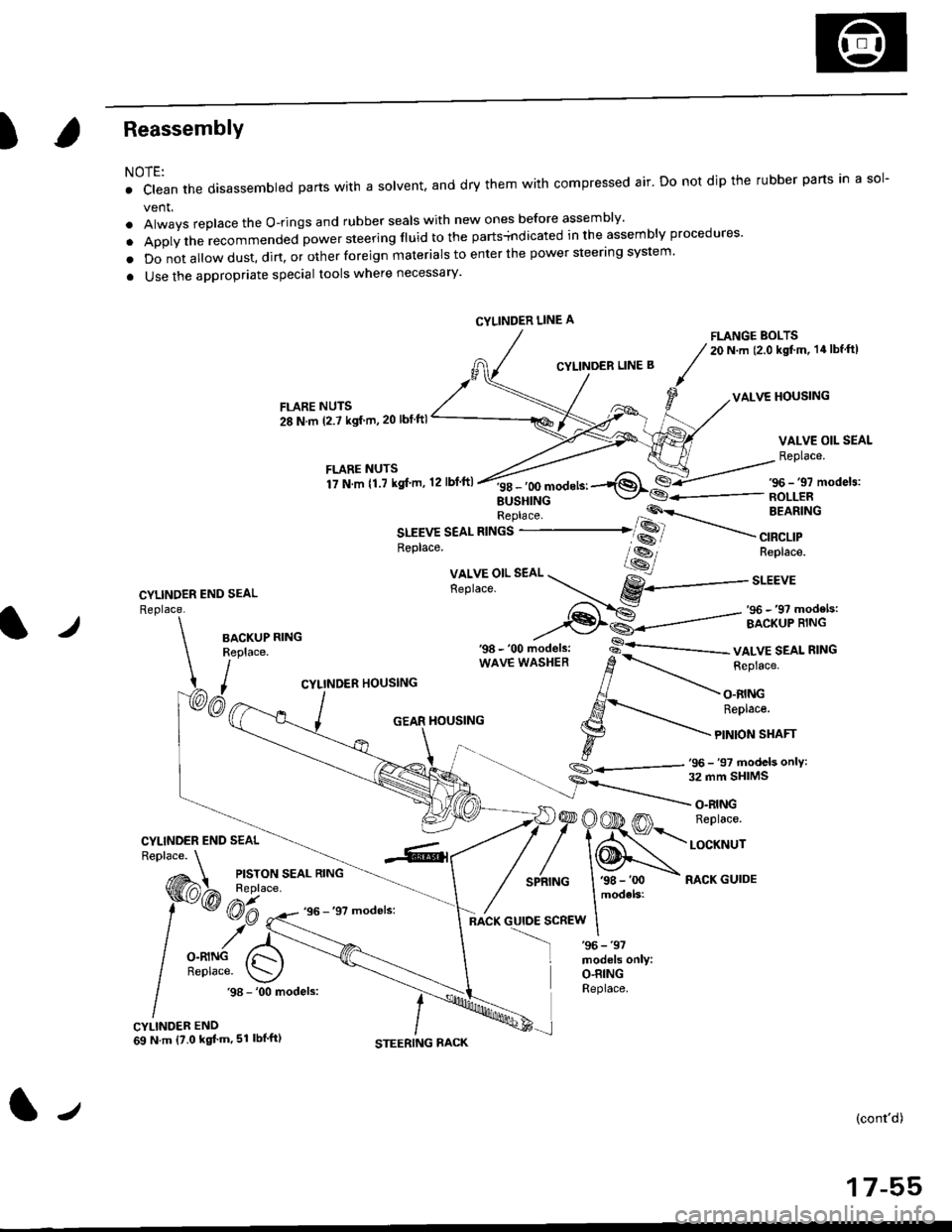
)Reassembly
NOTE:
. clean the disassembled parts wrth a solvent, and dry them with compressed air. Do not dip the rubber parts in a sol-
vent.
. Always replace the O-rings and rubber seals with new ones before assembly'
. Apply the recommended power steering fluid to the parts+ndicated in the assembly procedures'
o Do not a||ow dust, dirt, or other foreign materials to enter the power steering system.
a Use the appropriate special tools where necessary'
FLANGE BOLTS20 N.m (2.0 kgt'm, 14lbf ftl
CYLINDER LINE B
VALVE HOUSINGFLARE NUTS
28 N.m (2.7 ksf m,20 lbf ftl
VALVE OIL SEAL
Replace.
CYLINDER END SEAL
Replace.
f itllTllli".",'r'o,.n,ft
''*^'*-1$*€-/s6-,,mode,3:
EUSHINGReplace 'P'\-- BEARING
SLEEVE SEAL RINGS ..-------......�� SS
.----
",a"a,,
*---
--,
Replace. lss-, Replace.
Xll,Y5"l'.
"o. --r...- gY------..r.u,
,-f-..-S: _ ,96 _,9? models:
--€l€--------=- ircriip'ii.rt'-l./BACKUPReplace.
I,
wAvE wAsHER d
-.-.-r_ i"pru"".
CYLINDER HOUSING // -\-
, AJ - O.RING
/ ,S-'..- ReDtace.
_ j GEAR HouslNG l.g --'\-
\- t F
tonsrnrr
.,_- s
- 'oo ,,iod"t., -s-'--------- vALvE SEAL R'NG
S_.<---,tj- 97 models onlY:
CYLINDER END SEAL
)@OOD m n"prac".
/'\N,."._nrNG I '98 - 'oo - RACK GUIDE
models:
:scREw I
O.RINGReplace..98 - '00 models:
CYLINDER END69 N.m {?.0 kgt'm,51 lbl'ft)
(cont'd)
17-55
CYLINDER LINE A
tJ
Page 1112 of 2189
Steering Gearbox
Reassembly (cont'd)
Valve Body Unit Reassembly
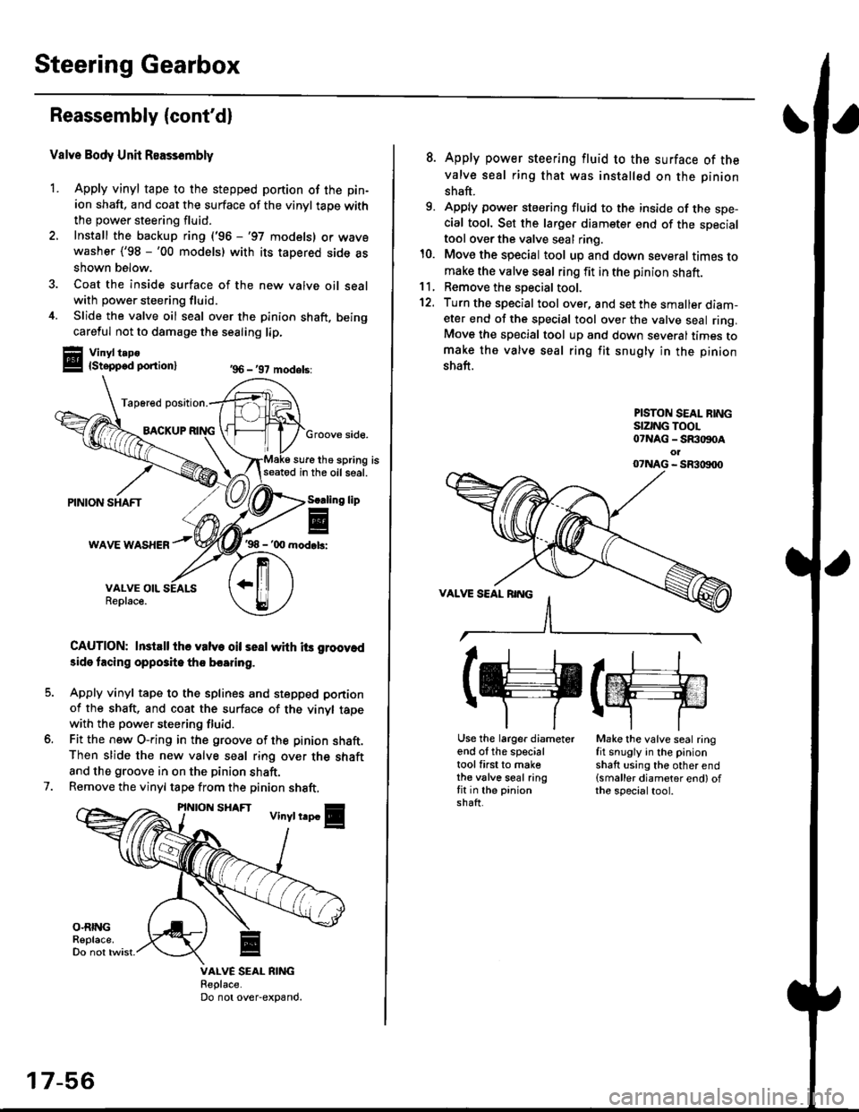
1. Apply vinyl tape to the stepped portion of the pin-
ion shaft, and coat the surface of the vinyl taoe with
the power steering fluid.
2. Install the backup ring ('96 -'97 models) or wavewasher ('98 -'00 models) with its tapered side as
shown below.
3. Coat the inside surface of the new valve oil sealwith power steering fluid.
4. Slide the valve oil seal over the pinion shaft, being
careful not to damage the sealing lip.
Vinyl t.po{Stepped ponion}
Tap6red position.
BACKUPGroove side.
sure the spring isseatod in the oil seal.
'98 - '00 mod.b:
CAUTION: InstEll ihe valve oil seal whh its groov.d
3ide tacing opposite tho boaring.
Apply vinyl tape to the splines and stepped portion
of the shaft, and coat the surface of the vinyl tapewith the power steering fluid.
Fit the new O-ring in the groove of the pinion shaft.Then slide the new valve seal ring over the shaft
and the groove in on the pinion shaft.
Remove the vinyl tape from the pinion shaft,
'96 - '97 models:
lip
7.
VALVE SEAL RIiIGReplace.Do not over-expand.
17-56
8. Apply power steering fluid to the surface of the
valve seal ring that was installed on the pinion
shaft.
9. Apply power steering fluid to the inside of the spe-cial tool. Set the larger diameter end of the specialtool over the valve seal ring.
10. Move the special tool up and down several times tomake the valve seal ring fit in the pinion shaft.11, Remove the soecial tool.
12. Turn the special tool over, and set the smaller diam-eter end of the special tool over the valve seal ring.Move the special tool up and down several times tomake the valve seal ring fit snugly in the pinion
shaft.
PISTON SEAL BINGSIZING TOOL07NAG - SR:togoAol07NAG - SR3|X)00
(g(m
Use the larger diameterend of the specialtool first to makethe valve seal ringfit in the pinionshaft.
Make the valve seal ringfit snugly in the pinionshaft using the other end(smaller diameter end) ofthe specialtool.
Page 1113 of 2189
I
14.
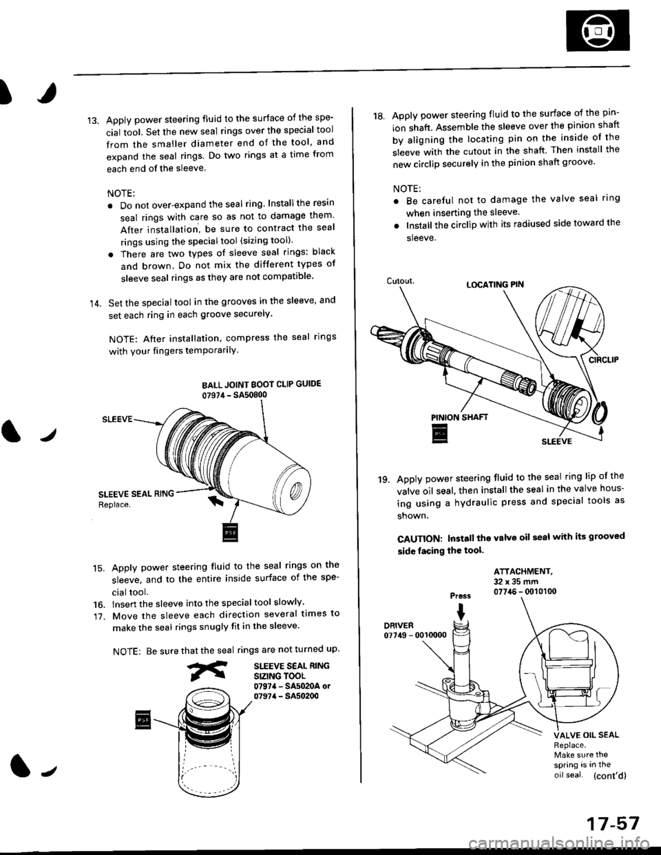
Apply power steering fluid to the surface of the spe-
cial tool. Set the new seal rings over the special tool
from the smaller diameter end of the tool, and
expand the seal rings. Do two rings at a time from
each end of the sleeve.
NOTE;
. Do not over-expand the seal ring. Installthe resin
seal rings with care so as not to damage them'
After installation, be sure to contract the seal
rings using the specialtool (sizing tool).
. There are two types of sleeve seal rings: black
and brown. Do not mix the different types of
sleeve seal rings as they are not compatible
Set the special tool in the grooves in the sleeve, and
set each ring in each groove securely.
NOTE: After installation, compress the seal rings
with your fingers temPorarilY
BALL JOINT BOOI CLIP GUIDE
07S7,1- SA50800
SLEEVE
15. Apply power steering fluid to the seal rings on the
sleeve, and to the entire inside surface of the spe-
cial tool.
16. lnsert the sleeve into the specialtool slowly'
17. Move the sleeve each direction several times to
make the seal rings snugly fit in the sleeve'
NOTE: Be surerings are not turned uP.
SITEVE SEAL RINGSIZING TOOL0797a - SA5020A or07974 - SA50200
that the seal
fr
J
17-57
18. Apply power steering fluid to the surface o{ the pin-
ion shaft. Assemble the sleeve over the pinion shaft
by aligning the locating pin on the inside of the
sleeve with the cutout in the shaft. Then install the
new circlip securely in the pinion shaft groove'
NOTE:
Be careful not to damage the valve seal ring
when inserting the sleeve.
Installthe circlip with its radiused side toward the
sleeve.
Apply power steering fluid to the seal ring lip of the
valve oil seal. then install the seal in the valve hous-
ing using a hydraulic press and special tools as
shown.
CAUTION: Install the valve oil seal with its grooved
side facing the tool.
'19.
ATTACHMENT.32x35mm0774.6 - q)101(x)Pre3s
IDRIVER07749 - 0010000
VALVE OIL SEALReplace.Make sure thespring is in the
oil seal. (cont'd)
Page 1114 of 2189
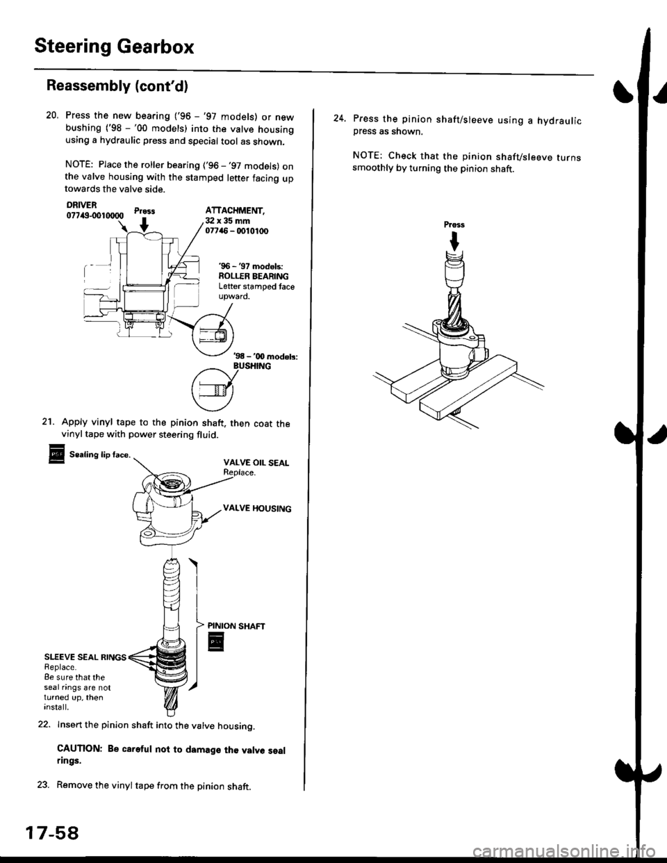
Steering Gearbox
Reassembly (cont'd)
SLEEVE SEAL RINGSReplace.8e sure that theseal nngs are notturned up, theninsta ll.
21. Apply vinyl tape to the pinion shaft. then coat thevinyltape with power steering fluid.
Sealing lip face.VALVE OIL SEAL
VALVE HOUSING
Press the new bearing ('96 - '97 models) or newbushing ('98 -'00 models) into the valve housingusing a hydraulic press and special tool as shown,
NOTE: Place the roller bearing ('96 -'97 models) onthe valve housing with the stamped letter facing uptowards the valve side.
DRIVER077itg-001tXlOO
22. Insert the pinion shaft into the valve housino.
CAUTION: Be careful noi to damage th€ valve sealrings.
23. Remove the vinyltape from the pinion shaft.
20.
Pr033
+3:Ix35mm07746 - 0010,t(x)
'96 - '97 models:ROLLER BEARINGLetter stamped taceupward.
ATTACHMENT,
'98 - '00 modob:
?/_vusHrNG
['---v-lt
\4)
PINION
E
17-5A
24. Press the pinion shaft/sleeve using a hydraulicpress as shown.
NOTE: Check that the pinion shafvsleeve turnssmoothly by turning the pinion shaft.
Page 1115 of 2189
)
Steering Rack Reassembly
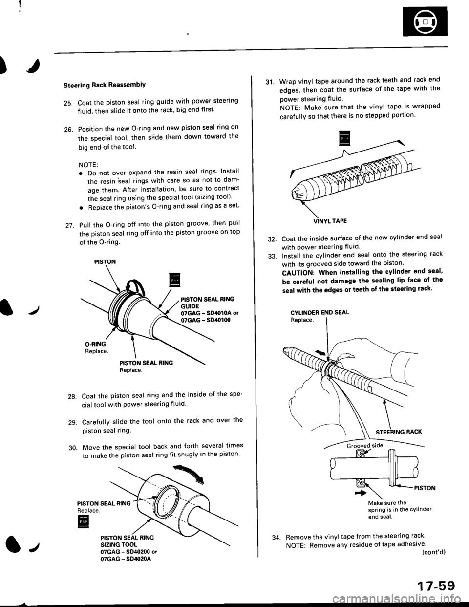
25. Coat the piston seal ring guide with power steering
fluid, then slide it onto the rack, big end first'
26. Position the new O-ring and new piston seal rlng on
the special tool, then slide them down toward the
big end of the tool
NOTE:
. Do not over expand the resin seal rings lnstali
the resin ;eal rings with care so as not to dam-
age them. After installation, be sure to contract
the seal ring using the specialtool (sizing tool)
. Replace the piston's O-ring and seal ring as a set'
27. Pull the O-ring off into the piston groove, then pull
the piston seal ring off into the piston groove on top
ol the O-ring
PISTON SEAL RINGGUIDE07GAG - SD4O10A ol
07GAG - SD,ol(xt
Coat the piston seal ring and the inside of the spe-
cial toolwith power steering fluid.
Carefully slide the tool onto the rack and over the
piston seal ring.
Move the special tool back and forth several times
to make the piston seal ring fit snugly in the piston'
PISTONReplace.
E
PISTON
31. Wrap vinyl tape around the rack teeth and rack end
edges, then coat the surface of the tape with the
power steering fluid
NOTE: Make sure that the vinyl tape is wrapped
carefully so that there is no stepped portion
Coat the inside surface of the new cylinder end seal
with power steering fluid.
Install the cylinder end seal onto the steering rack
with its grooved side toward the piston.
CAUTION: When installing the cylinder end seal,
be caieful not damage the sealing lip face of tho
seal with the edgss or teeth of th€ ste€ring rack'
CYLINDER END SEAL
Make sure thesPring is in the cylinder
end soal
Remove the vinyl tape from the steering rack
NOTE: Remove any residue oftape adhesive(cont'dl
17-59
Page 1116 of 2189
Steering Gearbox
Reassembly {cont'd)
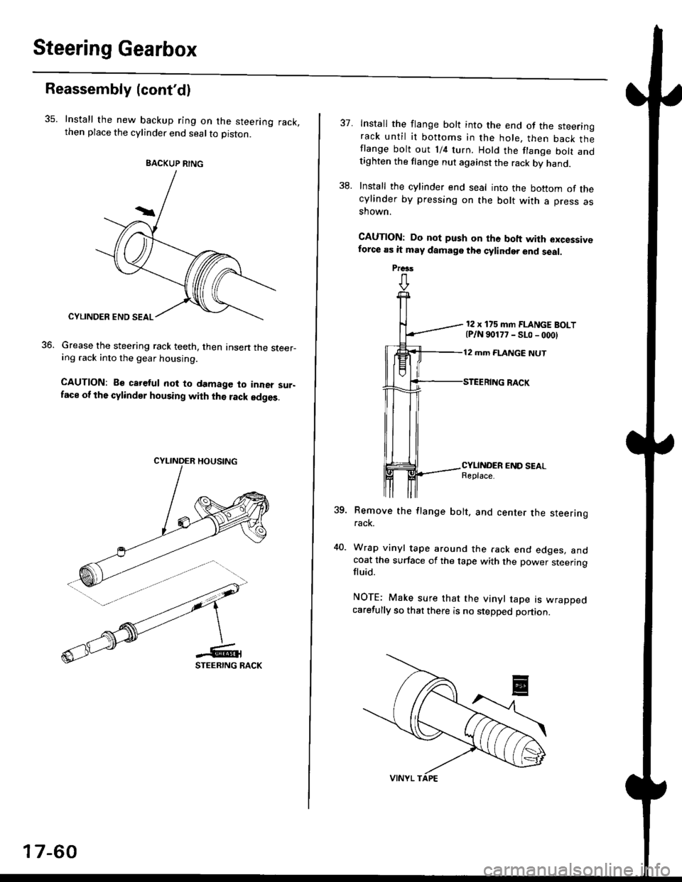
35. Install the new backup ring on the steering rack,then place the cylinder end seal to piston.
Grease the steering rack teeth, then Insen the steer-ing .ack into the gear housing.
CAUTION: Be careful not to damage to inner sur-face of the cylindsr housing with the rack edges.
36.
BACKUP RING
17-60
37. Install the flange bolt into the end of the steerinorack until it bottoms in the hole, then back thlflange bolt out 1/4 turn. Hold the flange bolt andtighten the flange nut against the rack by hand.
38. Install the cylinder end seal into the bottom of thecylinder by pressing on the bolt with a press asshown.
CAUTION: Do not push on the boh with excessiveforce as it may damage tho cylinder end seal.
12 x 175 mm FLANGE BOLT{P/N 90177 - SLo - 000}
12 mm FLANGE NUT
?qRemove the flange bolt. and center the steeringrack.
Wrap vinyl tape around the rack end edges. andcoat the surface of the tape with the power steeringfluid.
NOTE: Make sure that the vinyl tape rs wrappedcarefully so that there is no stepped portion.
Preas