1998 HONDA CIVIC Pin out
[x] Cancel search: Pin outPage 1415 of 2189
Overhaul
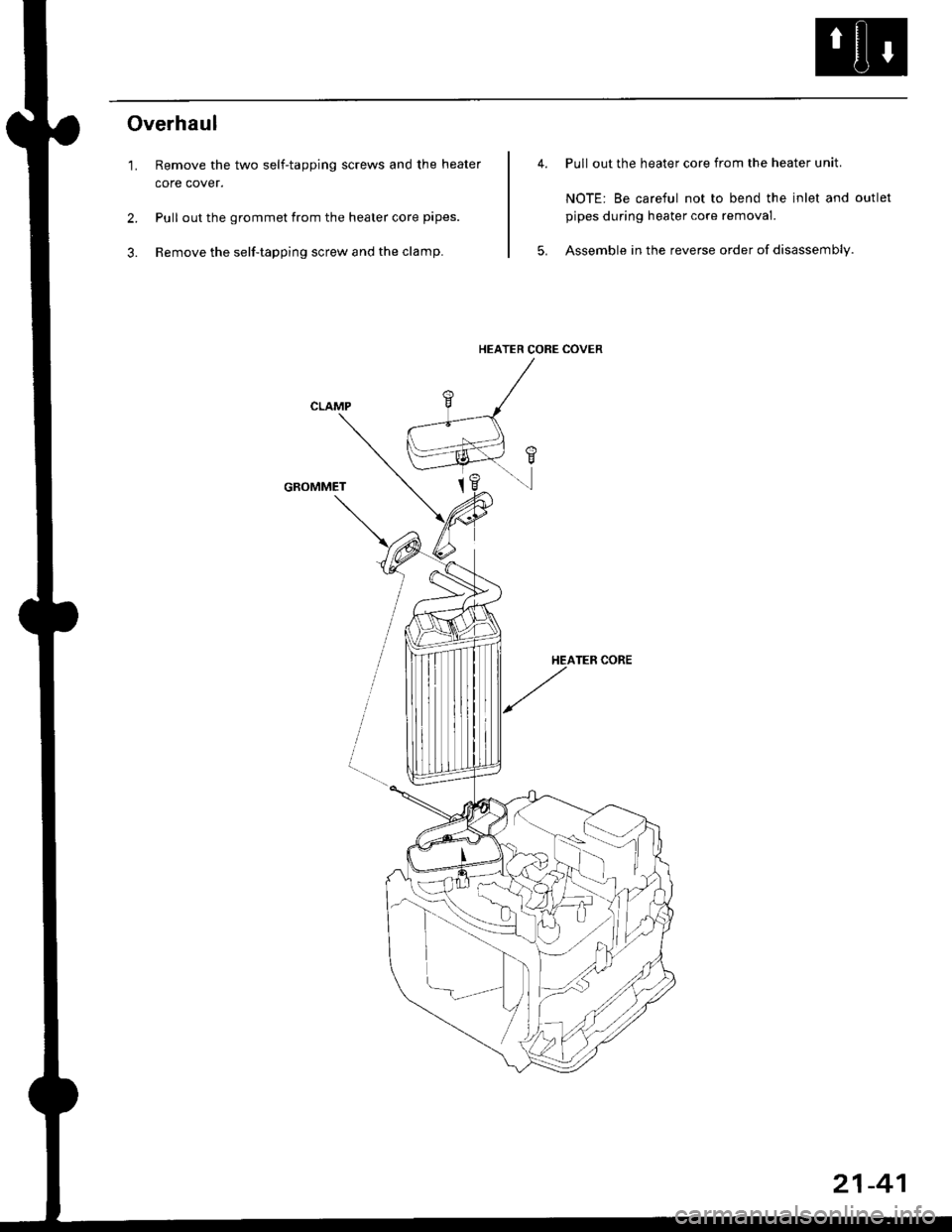
'1. Remove the two self-tapping screws and the heater
core cover.
2. Pull out the grommet from the heater core pipes.
3. Remove the self-tapping screw and the clamp.
GROMMET
Pull out the heater core from the heater unit.
NOTE: Be careful not to bend the inlet and outlet
pipes during heater core removal.
Assemble in the reverse order of disassembly.
HEATER CORE COVER
21-41
Page 1450 of 2189
A/C System Service
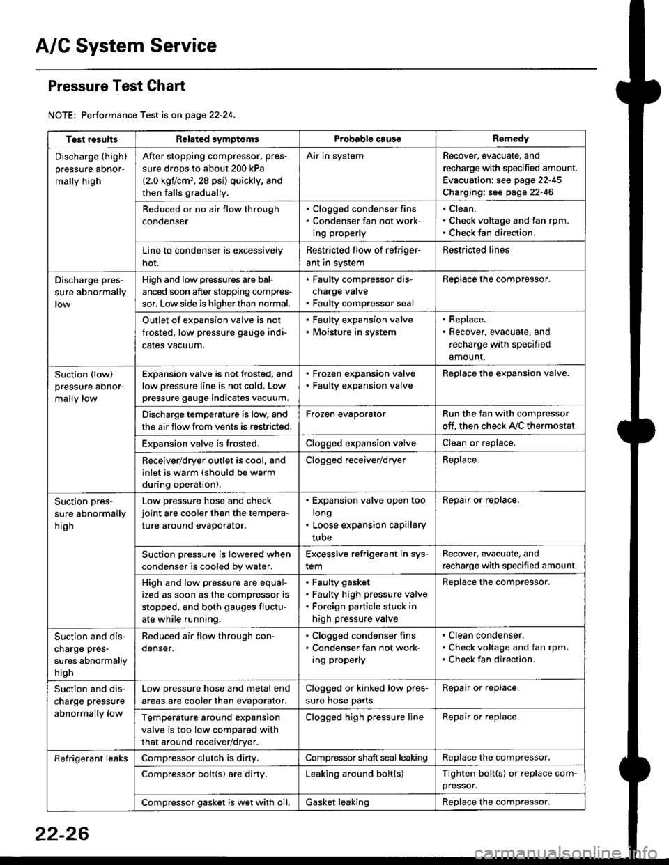
Pressure Test Chart
NOTE: Performance Test is on page 22-24,
Test resultsRelated symptomsProbabl€ causeRemedy
Discharge (high)
pressure aDnor-
mally high
After stopping compressor. pres-
sure drops to about 200 kPa
{2.0 kgflcm,,28 psi) quickly, and
then falls gradually.
Air in systemRecover, evacuate, and
recharge with specified amount.
Evacuation: see page 22-45
Charging: see page 22-46
Reduced or no air flow through
condenser
. Clogged condenser fins. Condenser fan not work-
ing properly
Clean.
Check voltage and fan rpm.
Check fan direction.
Line to condenser is excessively
hot.
Restricted flow of refriger-
ant in system
Restricted lines
Discharge pres-
sure abnormally
High and low pressures are bal-
anced soon after stopping compres-
sor, Low side is higher than normal.
. Faulty compressor dis-
charge valve. Faulty compressor seal
Replace the compressor.
Outlet of expansion valve is not
frosted, low pressure gauge indi-
cales vacuum.
. Faulty expansion valve. Moisture in system
. Replace,. Recover, evacuate, and
recharge with specified
amount.
Suction (low)
pressure abnor-
mally low
Expansion valve is not frosted, and
low oressure line is not cold. Low
pressure gauge indicates vacuum.
. Frozen expansion valve. Faulty expansion valve
ReDlace the exoansion valve.
Discharge temperature is low. and
the air flow from vents is restricted.
Frozen evaporatorRun the fan with compressor
off. then check A,/C thermostat.
Exoansion valve is frosted.Clogged expansion valveClean or replace.
Receiver/dryer outlet is cool, and
inlet is warm (should be warm
during operation).
Clogged receiver/dryerReplace.
Suction pres-
sure abnormally
hig h
Low pressure hose and check
joint are cooler than the tempera-
ture around evaporator.
. Expansion valve open too
long. Loose expansion capillary
tube
Repair or replace.
Suction oressure is lowered when
condenser is cooled bv water.
Excessive refrigerant in sys-
tem
Recover. evacuate, and
recharge with specified amount.
High and low pressure are equal-
ized as soon as the compressor is
stopped, and both gauges fluctu-
ate while running.
Faulty gasket
Faulty high pressure valve
Foreign particle stuck in
high pressure valve
Replace the compressor.
Suction and dis-
charge pres-
sures abnormally
h igh
Reduced air flow through con-
denser.
. Clogged condenser fins. Condenser fan not work-
ing properly
Clean condenser.
Check voltage and fan rpm.
Check fan direction.
Suction and dis-
charge pressure
abnormally low
Low pressure hose and metal end
areas are cooler than evaporator.
Clogged or kinked low pres-
sure hose parts
Repair or replace.
Temperature around expansion
valve is too low compared with
that around receiver/dryer.
Clogged high pressure lineRepair or replace.
Refrigerant leaksCompressor clutch is diny,Compressor shaft seal leakingReplace the compressor.
Compressor bolt{s) are diny.Leaking around bolt(s)Tighten bolt(s) or replace com-
pressor.
Compressor gasket is wet with oil.Gasket leakingReplace the compressor.
22-26
Page 1453 of 2189
Overhaul
1.
3.
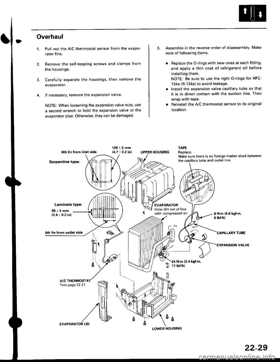
Pull out the A,/C thermostat sensor from the evapo-
rator fins.
Remove the self-tapping screws and clamps from
the housings.
Carefully separate the housings, then remove the
evaporator.
lf necessary, remove the expansion valve.
NOTE: When loosening the expansion valve nuts, use
a second wrench to hold the expansion valve or the
evaporator pipe. Otherwise, they can be damaged
5. Assemble in the reverse order of disassembly Make
note of following items.
. Replace the O-rings with new ones at each fitting,
and apply a thin coat of refrigerant oil before
installing them.
NOTE: Be sure to use the right O-rings for HFC-
134a (R-134a) to avoid leakage.
. Install the expansion valve capillary tube so that
it is in direct contact with the suction line. Then
wrap wath taPe.
. Reinstall the Ay'C thermostat sensor to its original
location.
6th tin lrom inld side
Serpentine type:
Laminate typo:
TAPEReplace.lvake sure there is no foreign matter stuck between
60t5mml'2.1! O.2 inl
EVAPORATORblow din out of linswith compressed air,
HOUSING
8 N.m 10.8 kgt m,6 tbf.ftl
6th fin lrom outle't sideCAPILLARY TUAE
VALVEN
u'
ll
6\N.m (2.it kgt.m,17 tbtftl1l
A/C THERMOSTfesr page 22 21
%
EVAPORA
LOWER
22-29
Page 1502 of 2189
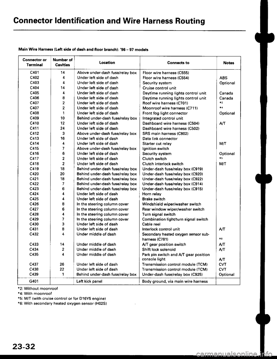
Connector ldentification and Wire Harness Routing
Connector or
Terminal
Number of
CavhiosLocationConnocts ioNotes
c401
c402
c403
c404
c405
c406
c407
c407
c408
c409
c410
c411
c412
c413
c414
c415
c416
c417
c418
c4l9
c420
c42'l
c423
c424
c425
c426
c427
c42A
c429
c430
c431
c432
c433
c434
c435
c431
c438
c439
'14
't4
I
I
10't2
24
16
7
o
18
20
18
7
6
I
o
4
7
8
14
1
Above under-dash fuss/relay box
Under left side ot dash
Under left sid€ of dash
Under left side of dash
Under left side of dash
Und€r left side of dash
Under left side of dash
Under left side of dash
Under left side of dash
Behind under-dash fuse/relay box
Under left side of dash
Under left side of dash
Above under-dash fuse/relay box
Under left side of dash
Under left side of dash
Above under-dash fuse/r€lay box
Under left side of dash
Under left side of dash
Under left side of dash
Behind under-dash fuse/relay box
Eehind under-dash fuse/relay box
Behind under-dash fuse/relay box
Behind under-dash fuse/relay box
Behind under-dash fuse/relay box
Under left side of dash
Under left side of dash
In the steering column cover
In the steering column cover
In the steering column cover
In the steering column covEr
Under left side of dash
Under left side of dash
Under middle of dash
Under middle of dash
Under middle of dash
Under middle of dash
Under left side of dash
Under left side of dash
Eehind under-dash fus€/relay box
Floo. wire harness (C555)
Floor wire harness (C554)
Security system
Cruise control unit
Daytime running lights control unit
Daytime running lights control unit
Roof wire harness (C701)
Moonroof wire harness (C7l1)
Front fog light connector
Integrated control unit
Dashboard wire harness (C504)
Dashboard wire harness (C502)
SRS main harness (C802)
Data link connector
Starter cut relay
lgnition switch
Security system
Clutch switch
Clutch interlock switch
Under-dash fuss/relay box (C9191
Undor-dash fuse/r€lay box {C920)
Under-dash tuse/relay box (C922)
Under-dash luse/relay box (C914)
Under-dash fuse/rBlay box (C915)
Horn relay
Brake swilch
Windshield wiper/washer switch
Rear window wiper/washer switch
Turn signal switch
Combination lighvturn signal switch
Cable reel
lnterlock control unit
Secondary heated oxygen sensor sub-
harn€ss (C781)
Ay'T gear position switch
Shift lock solenoid
Park pin switch and Ay'T gear position
console light
Transmission control module (TCM)
Transmission control module {TCM)
Under-dash fuse/relay box {C925)
ABS
Optional
Canada
Canada
Optional
Atr
MTT
Optional
Mlf
NT
Atf
CVT
CVT
Optional
AN
Atr
G401Left kick panelBody ground, via main wire harness
Main Wir€ Harness (Loft side of da3h and floor branch): '96 - 97 models
*2:Without moonroof*4: With moonroof*5: M/T (with cruise control or for D16Y5 engine)*6: With secondary heated oxygen sensor (H02S)
23-32
Page 1504 of 2189
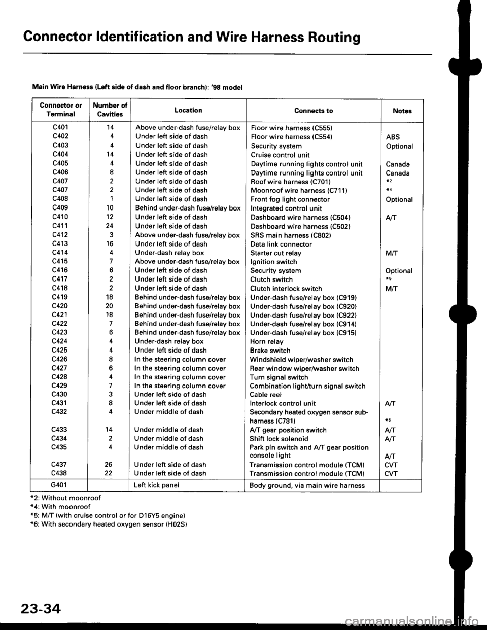
Connector ldentification and Wire Harness Routing
Connoctor or
Tgrminal
Number of
CavitiesLocationConneqts toNot€s
c401
c402
c403
c404
c405
c406
c407
c407
c408
c409
c410
c411
c4't2
c413
c414
c415
c416
c417
c418
c419
c420
c421
c422
c423
c424
c425
c426
c427
c428
c429
c430
c431
c432
c433
c434
c435
c437
c438
't4
l4
8,
1
10
12
24
7
6
18
20
18
7
6
8
7
8
14
2
Above under-dash fuse/relay box
Under left side of dash
Under left side of dash
Under left side of dash
Under left side of dash
Under left side of dash
Under left side of dash
Under left side of dash
Under left side of dash
Behind under-dash fuss/relay box
Under left side of dash
Under left side of dash
Above under-dash fuse/relay box
Under left side of dash
Under-dash relay box
Above under-dash fuse/relay box
Under left side of dash
Under left side of dash
Under left side of dash
Eehind under-dash fuse/relay box
Behind under-dash fuse/relay box
Behind under-dash fuse/relay box
Behind under-dash fuse/rslay box
Behind under-dash fuse/relay box
Under-dash relay box
Under left side of dash
In the steering column cover
In the steering column cover
In the steering column cover
In the steering column cover
Under left side of dash
Under left side of dash
Under middle of dash
Under middle of dash
Under middle of dash
Under middle of dash
Under left side of dash
Under left side of dash
Floor wire harness (C555)
Floor wire harness (C554)
Security system
Cruise control unit
Daytime running lights control unit
Daytime running lights control unit
Roof wiro harness (C7011
Moonroof wire harness (C711)
Front fog light connector
Integrated control unit
Dashboard wire harness (C504)
Dashboard wire harness (C502)
SRS main harness (C802)
Data link connector
Starter cut relay
lgnition switch
Security system
Clutch switch
Clutch inlerlock switch
Under-dash fuse/relay box (C919)
Under-dash fuse/relay box (C920)
Under-dash fuse/relay box (C922)
Under-dash fuse/relay box (C914)
Under-dash fuse/relay box (C915)
Horn relay
Brake switch
Windshield wiper/washer switch
Rear window wiper/washer switch
Turn signal switch
Combination light/,turn signal switch
Cable reel
lnterlock control unit
Secondary heated orygen sensor sub-
harness (C781)
Ay'T gear position switch
Shift lock solenoid
Park pin switch and Aff gear position
console light
Transmission control module (TCMI
Transmission control module (TCM)
ABS
Optional
Canada
Canada
Optional
M
MIT
Optionsl
MlT
Alr
NT
NT
CVT
CVT
G401Left kick panelBody ground, via main wire harness
Main Wire Harn€ss {Left side ot dash and floor branchl: '98 model
*2: Without moonroof*4:With moonroof*5: M/T (with cruise control or for D16Y5 engine)*6: With secondary heated oxygen sensor (H02S)
23-34
Page 1506 of 2189
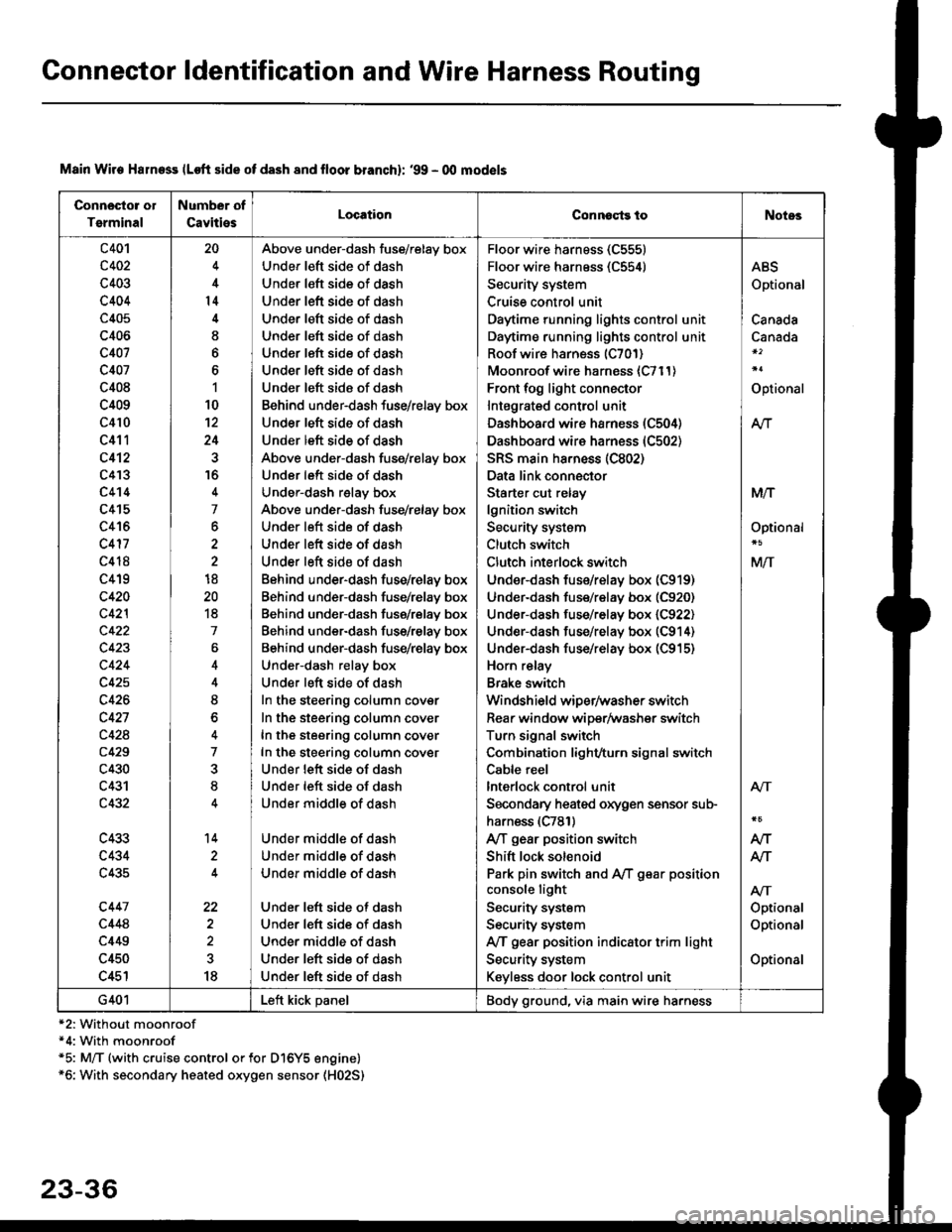
Connector ldentification and Wire Harness Routing
Connosto! ol
Tsrminal
Number of
CavitiesLocationConnoqtg toNotes
c401
c402
c403
c404
c405
c406
c407
c407
c408
c409
c410
c411
c412
c4'�I3
c4't4
c415
c416
c417
c418
c419
c420
c42l
c422
c423
c424
c425
c426
c427
c428
c429
c430
c431
c432
c433
c434
c435
c447
c448
c449
c450
c451
20
4
14
I
6
1
10
12
24
16
4
7
6
2
18
20
18
7
4
8
o
7
8
14
22
18
Above under-dash fuse/relay box
Under left side of dash
Under left side of dash
Under left side of dash
Under left side of dash
Under left side of dash
Under left side of dash
Under left side of dash
Under left side of dash
Behind under-dash fuse/relay box
Under left side of dash
Under left side of dash
Above under-dash fuse/relay box
Under left side of dash
Under-dash relay box
Above under-dash fuse/relay box
Under left side of dash
Under left side of dash
Under left side of dash
Behind under-dash fuse/relay box
Behind under-dash fuse/relay box
Behind under-dash fuse/relay box
Behind under-dash fuse/relay box
Behind under-dash fuse/relay box
Under-dash relay box
Under left side of dash
In the steering column cover
In the steering column cover
In the steering column cover
In the steering column cover
Under lett side of dash
Under left side of dash
Under middle of dash
Under middle of dash
Under middle of dash
Under middle of dash
Under left side of dash
Under left side of dash
Under middle of dash
Under left side of dash
Under left side of dash
Floor wire harness (C555)
Floor wire harness (C554)
Security system
Cruise control unit
Daytime running lights control unit
Daytime running lights control unit
Roof wire harness (C701)
Moonroof wire harness {C711)
Front fog light connector
Intagrated control unit
Dashboard wire harness (C504)
Dashboard wire harness (C502)
SRS main ha.ness (C802)
Data link connector
Starter cut relay
lgnition switch
Security system
Clutch switch
Clutch interlock switch
Under-dash fus€/relay box (C919)
Under-dash fuse/relay box (C920)
Under-dash fuse/relay box (C922)
Under-dash fuse/relay box (C914)
Under-dash fuse/relay box (C915)
Horn relay
Brake switch
Windshield wiper/washer switch
Rear window wiper/Washer switch
Turn signal switch
Combination light/turn signal switch
Cable reel
lnterlock control unit
Secondary heaied oxygen sensor sub-
harness (C781)
A/T gear position switch
Shift lock solenoid
Park pin switch and A,/T g€ar position
console light
Security system
Security system
IVT gear position indicator trim light
Security system
Keyless door lock control unit
ABS
Optional
Canada
Canada
Optional
At-|.
M/T
Optional
M/T
Atr
Optional
Optional
Optional
Atr
AIT
AJ-|.
G401Left kick panelBody ground, via main wire harness
Main Wire Halness lLoft side of dash 8nd lloor branchl: '99 - 00 mod€ls
*2: Without moonroof*4: With moonroof*5: M/T (with cruise control or for Dl6Y5 engine)*6: With secondary heated oxygen sensor (H02S)
23-36
Page 1571 of 2189
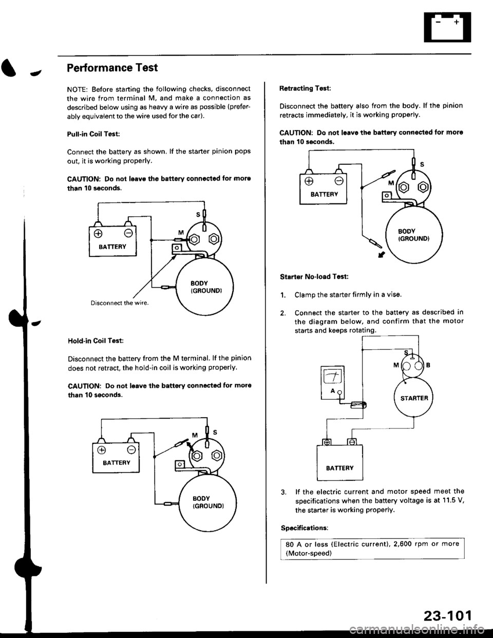
-Performance Test
NOTE: Before staning the following checks. disconnect
the wire from terminal M. and make a connection as
described below using as heavy a wire as possible (prefer-
ably equivalent to the wire used for the car).
Pull-in CoilTest:
Connect the battery as shown, lf the staner pinion pops
out. it is working proPerly.
CAUTION: Do not leavo tho batterv connost€d for more
than 10 seconds.
Hold-in Coil Test:
Disconnect the battery from the M terminal' lf the pinion
does not retract, the hold-in coil is working properly.
CAUTION: Do not loavc lhe battsry connected for mot6
than 10 ssconds.
Retracting Tosi:
Disconnect the battery also from the body. lf the pinion
retracts immediately, it is working properly.
GAUTION: Do not loave the baftery conn€ctod tor more
than 10 seconds.
Startor No-load Tost:
Clamp the starter firmly in a vise.
Connect the starter to the battery as described in
the diagram below, and confirm that the motor
starts and keeps rotating.
1.
3, lf the electric current and motor speed
specifications when the battery voltage is
the starter is working ProPerly.
Specifications:
80 A or less (Electric current),2,600 rpm or more
(Motor-speed)
meet the
at 11.5 V,
23-101
Page 1594 of 2189
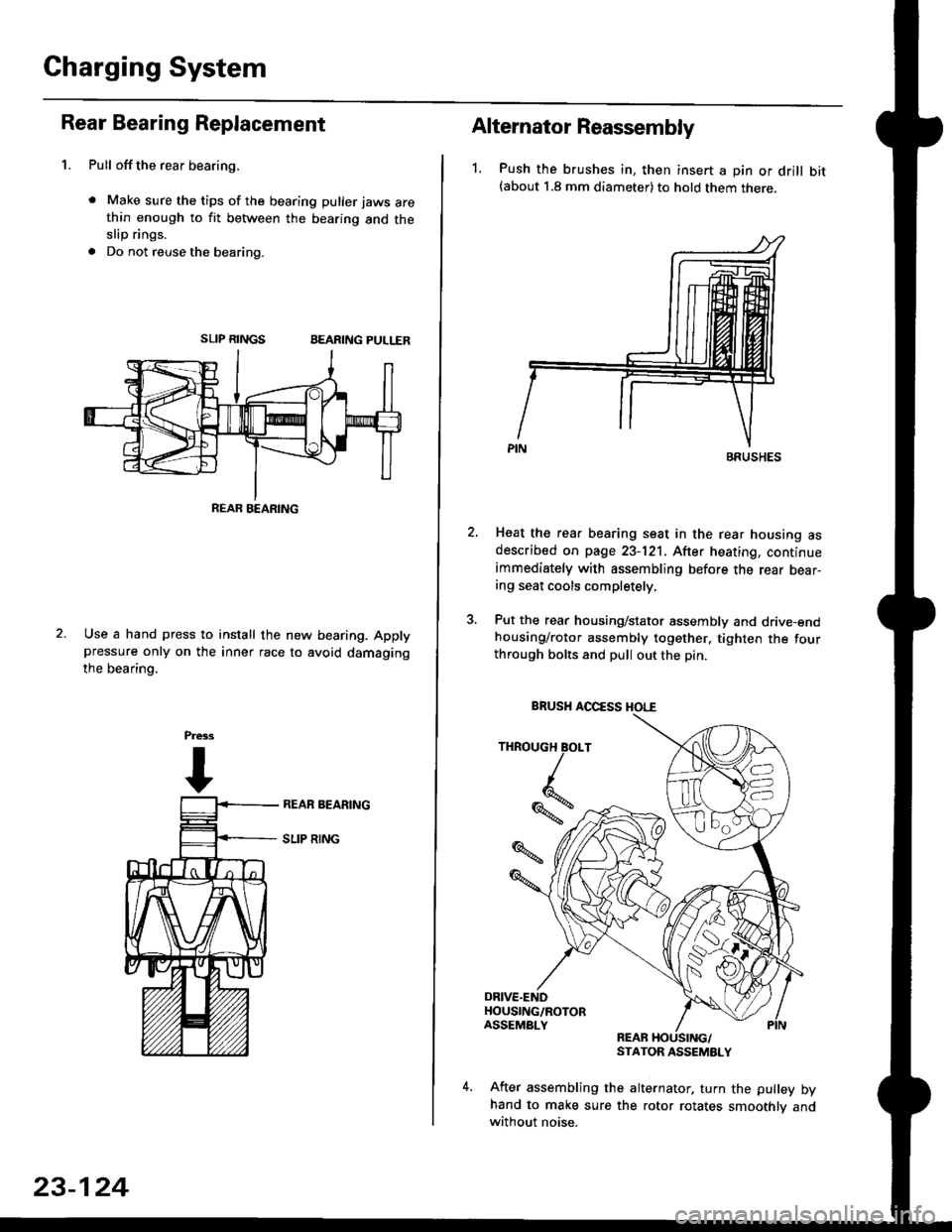
Gharging System
Rear Bearing Replacement
1. Pull offthe rear bearing,
. Make sure the tips of the bearing puller jaws arethin enough to fit between the bearing and theslip rings.
. Do not reuse the bearing.
SLIP RINGSBEARING PULLER
Use a hand press to install the new bearing. Applypressure only on the inner race to avoid damaging
the bearino.
REAB BEARING
23-124
Alternator Reassembly
1. Push the brushes in, then insert a pin or drill bit(about 1.8 mm diameter) to hold them there.
Heat the rear bearing seat in the rear housing asdescribed on page 23-121. After heating, continueimmediately with assembling before the rear bear-ing seat cools completely,
Put the rear housing/stator assembly and drive-endhousing/rotor assembly together. tighten the fourthrough bolts and pull out the pin.
REARSTATOR ASSEMBLY
After assembling the alternator, turn the pulley byhand to make sure the rotor rotates smoothlv andwithout noise.
BRUSHES
THROUGH BOLT
Iq
%*z
BRUSH AOCESS HOI."E