Page 1027 of 2189

22. Install the shift cable end on the control lever, and
install the shift cable on the shift cable bracket'
CAUTION: Take care not to bend the shift cable'
23. lnstall the clip in the direction shown.
LOCKNUT
SHIFI CABLE 29 N m {3.0 kg{ m, 22lblftl
SHIFT CABLEERACKET
WASHERIPLASTIC)
CONTROL LEVER
24, Connect the solenoid harness connector. the drive
pulley speed sensor connector. and the ground
cable terminals.
6x1.0mm12 N.m {1.2 kgf.m.8,7 rbtft)
GROUND CABLETERMINAL 6x1.0mm
GROUNDTERMINAL
12 N.m {1.2 kgf'm,8.7lbtfrl
DRIVE PULLEYSPEED SENSORCONNECTOR
SOLENOID HARNESS
CONNECTOR
25. Connect the starter motor cable on the starter motor.
and install the cable holder.
NOTE: When installing the staner motor cable. make
sure that the crimped side of the ring terminal is
facing out (see section 23).
STARTEB
BMOUNTING NUT
9 N.m (0.9 kgf m,7 lbf ft)
26. Install all removed connectors and clamps'
27. Install the distributor.
28. Install the intake air duct and air cleaner housing
29.
assemDly.
Refill the transmission with the recommended
Genuine Honda CVT Fluid (see page 14-2991
CAUTION: While filling the CvT Fluid, bs surs not io
allow dust and other fotoign particles to entor into
the transmission.
Connect the battery positive (+) terminal first, then
the negative (-l terminal to the battery'
Check the ignition timing (see section 23).
Start the engine. Set the parking brake, and shift the
transmission through all gears three times Check
shift cable adjustment (see page 14-355).
Check the front wheel alignment (see section 18)
Let the engine reach operating temperature (the
radiator fan comes on) with the transmission in lXl
or E position, then turn it off and check fluid level'
Perform the start clutch calibration procedure on
page 14-293.
Road test as described on pages 14-296 and 14-297
30.
31.
34.
36.
STARTER MOTOR
14-351
Page 1033 of 2189
Shift Indicator PanelATF Gooler/Hoses
Adjustment
1.Check that the index mark on the indicator aligns
with the E mark on the shift indicator panel when
the transmission is in NEUTRAL.
lf not aligned, remove the front console {see section
20).
Remove the shift indicator panel mounting
and adjust by moving the panel.
NOTE: Whenever the shift indicator panel is removed,
reinstallthe Danel as described above.
It,
14-357
lnstallation
1. Installthe ATF cooler, ATF cooler line assembly and
the ATF cooler hoses.
6x1.0mm11 N.m ('l 1 kgf.m,8.0lbl'ftlATF COOLER LINE ASSEMBLY
ATF COOLER HOSE
RADIATOR
6x1.0mm9.8 N.m 11.0 kgf'm, 7 8 lbf'ft)
ATF COOLER
Connect the ATF cooler
lines and ATF cooler. and
as shown.
hoses to the ATF cooler
secure them with the clips
1l lTf{il.T
6-8mm10.2 - 0.3 in)
33-35mm11.3 - 1.4 inl
2-1mm10.1 - 0.2 in)
2-ilmm{0.1 - 0.2 in)
ATF COOI..ER HOSES
Page 1060 of 2189

Inspection and Adjustment
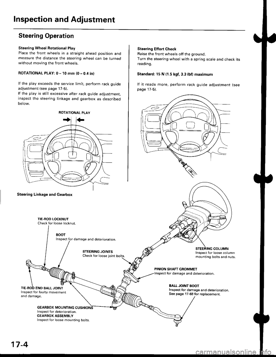
Steering Operation
Steering Wheel Rotational Play
Place the front wheels in a straight ahead position andmeasure the distance the steering wheel can be turnedwithout moving the front wheels.
ROTATIONAL PLAY: 0 - 10 mm (0 - 0.4 in)
lf the play exceeds the service limit, perform rack guide
adjustment (see page lT-5).
lf the play is still excessive after rack guide adjustment,inspect the steering linkage and gearbox as descrjbed
Detow.
Steering Linkage and Gearbox
TIE.ROO LOCKNUTCheck for loose locknut.
BOOTInspect for damage and deterioration.
STEERING JOINTSCheck for loose joint
END BALL JOINTInspect for faulty movementano oamage.
GEABBOX MOUNTINGInspect f or deterioration.GEABBOX ASSEMBLY
Ste€ring Effort Check
Raise the front wheels off the ground.
Turn the steering wheel with a spring scale and check itsreaorng,
Standard: 15 N (1.5 kgf, 3.3 lbll maximum
lf it reads more. perform rack guide adjustment (see
page 17-5).
COLUMNInspect for loose columnmounting bolts and nuts.
PINION SHAFT GROMMETfor damage and deterioration.
BALL JOINT BOOTInspect for damage and deterioration.See pago 17-68 tor replacement.
ao-\---------U
17-4
Inspect for loose mounting bolts.
Page 1062 of 2189

Steering Gearbox
Removal(cont'd)
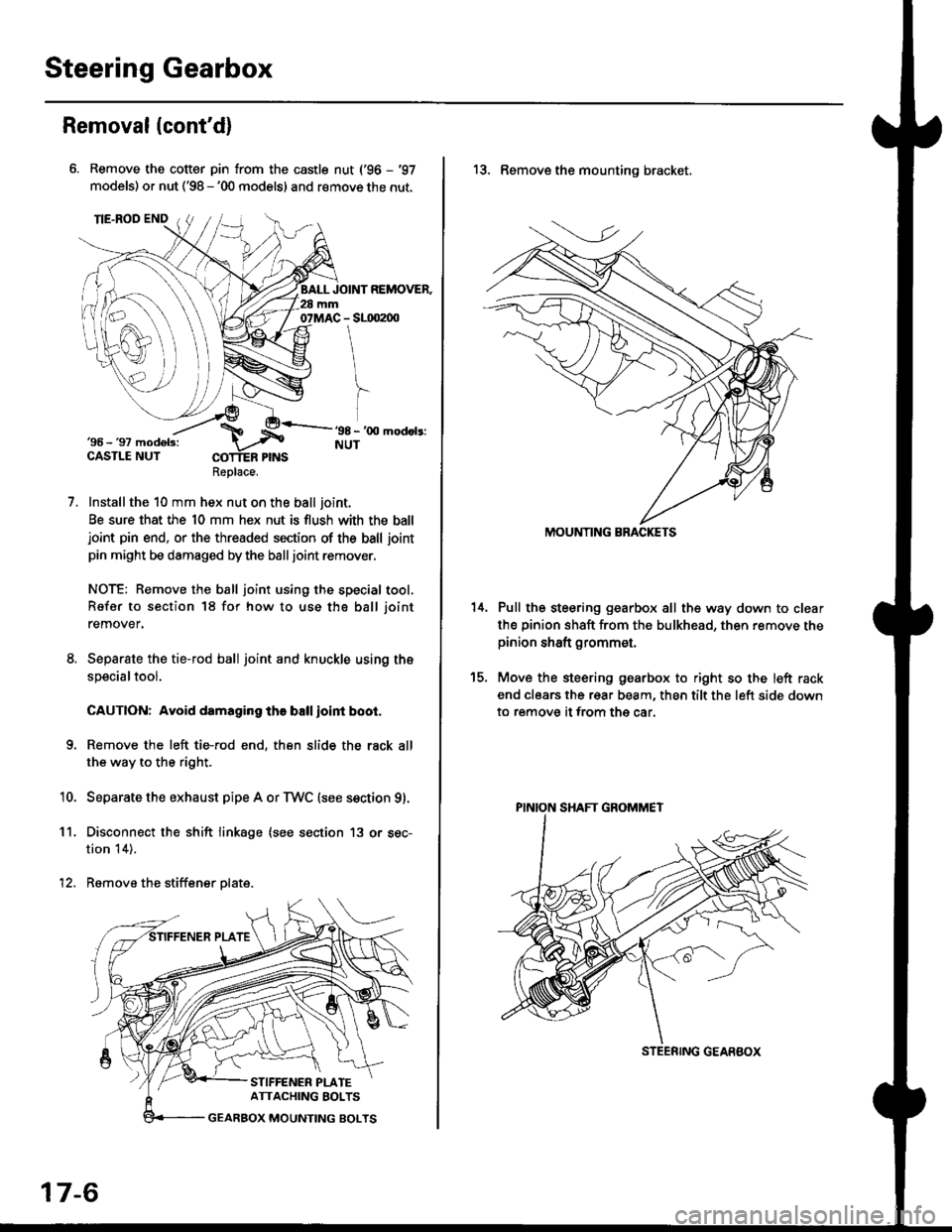
Remove the cotter pin from the castle nut ('96 - '97
models) or nut ('98 - '00 models) and remove the nut.
Installthe 10 mm hex nut on the ball joint.
Be sure that the 10 mm hex nut is flush with the balljoint pin end, or the threaded section of the ball joint
pin might be damaged by the balljoint remover.
NOTE: Remove the ball joint using the special tool,
Refer to section 18 for how to use tho ball joint
remover.
Separate the tie-rod ball joint and knuckle using the
specialtool.
CAUTION: Avoid damaging the ball ioint boot.
Remove the left tie-rod end, then slide the rack all
the way to the right.
Separate the exhaust pipe A or TWC (see section g).
Disconnect the shift linkage (see section 13 or sec-
tion 14).
Remove the stiffener plate.
7.
'10.
11.
12.
Replace.
17-6
13. Remove the mounting bracket,
Pull the steering gearbox all the way down to clear
th€ pinion shaft from the bulkhead, then remove thepinion shaft grommet,
Move the steering gearbox to right so the left rack
end clears the rear beam, then tilt the left side down
to remove it from the car.
t5.
STEENING GEARBOX
PINION SHAFT GROMMET
Page 1063 of 2189

)
Disassembly
'1.
2.
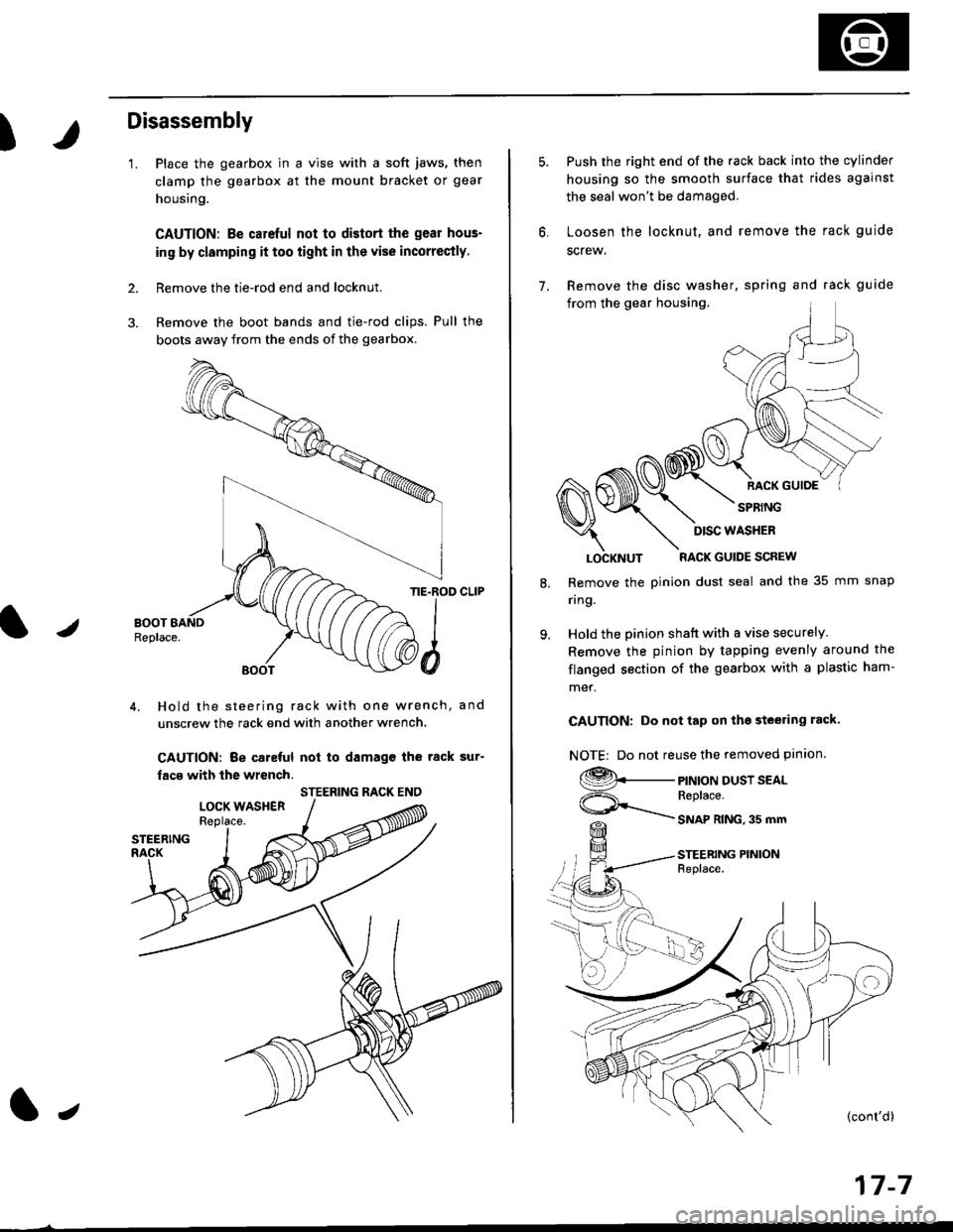
Place the gearbox in a vise with a soft jaws, then
clamp the gearbox at the mount bracket or gear
housing.
CAUTION: Be carcful not to distort the gear hous-
in9 by clamping it too iight in the vise incorrectly.
Remove the tie-rod end and locknut.
Remove the boot bands and tie-rod clips. Pull the
bogts away from the ends of the gearbox.
/
TIE.ROD CLIP
4. Hold the steering rack with one wrench, and
unscrew the rack end with another wrench.
CAUTION: Be caleful not to damagc the rack sur'
facs with the wrench.
STEERING RACK ENO
l,
17-7
7.
Push the right end of the rack back into the cylinder
housing so the smooth surface that rides against
the seal won't be damaged.
Loosen the locknut, and remove the rack guide
screw.
Remove the disc washer, spring and rack guide
from the gear housing.
RACK GUIOE
SPRING
8.
9.
LOCKNUT RACK GUIDE SCREW
Remove the pinion dust seal and the 35 mm snap
nng.
Hold the pinion shatt with a vise securely
Remove the pinion by tapping evenly around the
flanged section of the gearbox with a plastic ham-
met.
CAUTION: Do not tap on tho steering rack.
NOTE| Do not reuse the removed pinion.
9._
ViF=\_
PINION DUST SEALReplace.
SNAP RING,35 mm
STEERING PINIONFeplace.
DISC WASHER
Page 1064 of 2189
Steering Gearbox
Disassembly (cont'dl
10. Slide the steering rack out of the cylinder housing.
CAUTION: Be carelul not to damage the bushing in
the cylinder housing.
11. Remove the rack end bushing.
GEARBOX MOUNTING CUSHION
Inspect inner wall tor wear or damage.
17-8
12. Replace the gearbox mounting cushion if necessary:
. To remove the cushion, use a sharp knife and make
a cut down the length of the cushion. Be careful not
to damage the paint on the outside of the cylinder
housing. Remove the old cushion.. Apply weatherstrip adhesive to the inside of the
new cushion. Install the cushion onto the cylinder
housing and position it 20 - 22 mm (0.79 - 0.87 in)
from the end of the cylinder housing as shown.
NOTE: After installing the cushion, wipe off any
excess adhesive that may have dripped into the
inside of the cylinder housing.
20 - 22 mm 10.79 - 0.87 in)
Page 1065 of 2189
Reassembly
NOTE:
. Clean the disassembled parts with solvent, and dry them with compressed air. Do not dip the rubber parts in solvent.
. Alwavs replace the non reuseable parts with new ones before assembly
. Do not allow dust, dirt, or other foreign materials to enter the steering gearbox.
-6,1
PINION OUST SEALReplace.RACK ENO BUSHING
\
^lr
r@
-6i
GEARBOX MOUNTING CUSHIONS
V."^pR,NG,3smm
tr
a/
^$'q0
")*o''o"'"'*
DISC WASHER
RACK GUIDE
(cont'd)
17-9
tJ
Page 1069 of 2189

)
lnstallation
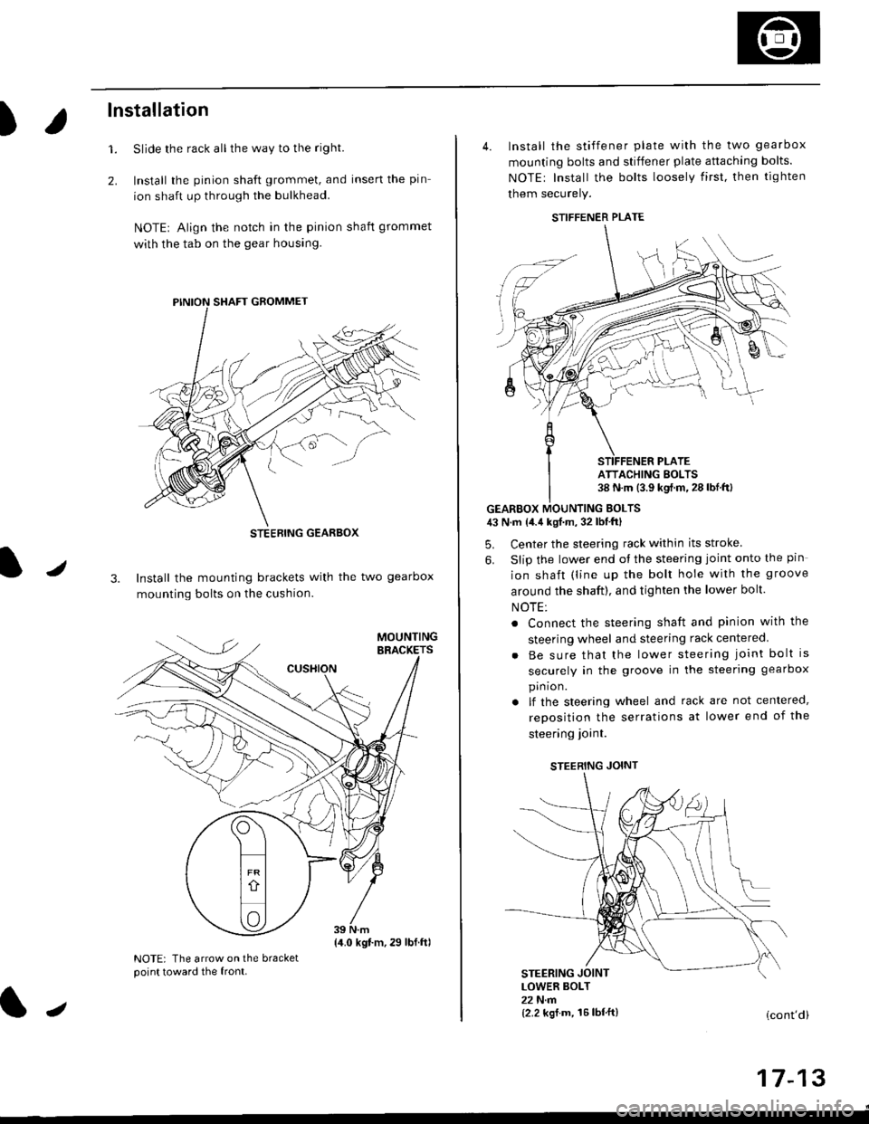
Slide the rack all the way to the righl
Install the pinion shaft grommet, and insert the pin
ion shaft up through the bulkhead.
NOTE| Align the notch in the pinion shaft grommet
with the tab on the gear housing.
1.
2.
J3. Install the mounting brackets with the two gearbox
mounting bolts on the cushion.
NOTE: The arrow on the bracketpoint toward the front.
STEEBING GEARBOX
{4.0 kgt.m,29 lbf.ftl
J
4. Install the stiffener plate with the two gearbox
mounting bolts and stiffener plate attaching bolts.
NOTEr Install the bolts loosely first. then tighten
them securely.
GEARBOX MOUNTING EOLTS43 N.m {4.4 kgf.m, 32 lbf'ftl
5. Center the steering rack within its stroke
6. Slip the lower end ot the steering joint onto the pin
ion shaft (line up the bolt hole with the groove
around the shaft), and tighten the lower bolt.
NOTE:
. Connect the steering shaft and pinion with the
steering wheel and steering rack centered
Be sure that the lower steering joint bolt is
securely in the groove in the steering gearbox
pin ion.
lf the steering wheel and rack are not centered,
reposition the serrations at lower end of the
steering ioint.
STEERING JOINT
STEERING JOINTLOWER BOLT22 N.m{2.2 kgf.m, 16lbf'ft}(cont'd)
I t- t5
STIFFENER PLATE
ATTACHING BOLTS38 N.m (3.9 kgf.m.28lbf.ftl