Page 713 of 2189
I
TOROUE CONVERTER
No Lock-up
. Lock-up Control Solenoid Valve A: OFF
. Lock-up Control Solenoid Valve B: OFF
. Linear Solenoid Pressure: High
The pressurized fluid regulated by the modulator works
on both ends of the lock-up shift valve. Under this condi-
tion, the pressures working on both ends of the lock-up
shift valve are equal, the lock-up shift valve is moved to
the right side by the tension of the valve spring alone.
The fluid from the ATF pump will flow through the left
side of the lock-up clutch to the torque convener; that is,
the lock-up clutch is in OFF condition.
NOTE: When used, "left" or "right" indicates direction
on the hydraulic circuit.
MOOULATOR PRESSURE
LINEAR SOLENOIO PRESSURE
(cont'd)
LOCK.UP CONTROLSOLENOID VALVE
RELIEF VALVE
LOCK-UP TIMINGVALVE
9 L ] I COOLER RELIEF VALVE
ATF PUMP
14-35
Page 714 of 2189

Description
Lock-up System (cont'dl
TOROUE CONVERTER
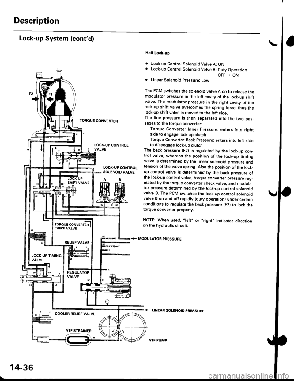
Half Lock-up
. Lock-up Control Solenoid Valve A: ONLock-up Control Solenoid Valve 8: Duty Operation
OFF - ONLinear Solenoid Pressure: Low
The PCM switches the solenoid valve A on to release themodulator pressure in the left cavity of the lock_up shiftvalve. The modulator pressure in the right cavity of thelock-up shift valve overcomes the spring force; thus thelock-up shift valve is moved to the left side.The line pressure is then separated into the two pas-sages to the torque converter:
Torque Converter Inner pressure: enters into rightsade to engage lock-up clutch
Torque Converter Back pressure: enters into left sideto diseogage lock-up clutchThe back pressure (F2) is regulated by the lock-up con-trol valve, whereas the position of the lock-up timingvalve is determined by the linear solenoid Dressure andtension of the valve spring. Also the position of the lock_up control valve is determined by the back pressure ofthe lock-up control valve, torque converter pressure reg_ulated by the torque converter check valve, and modula_tor pressure determined by the lock-up control solenoidvalve B. The PCM switches the lock-up control solenoidvalve B on and off rapidly {duty operation} under certainconditions to regulate the back pressure (F2) to lock thetorque convener properly.
NOTE: When used, "left" or "right" indicates directionon the hvdraulic circuit.
MODULATOR PRESSURE
LINEAR SOLENOTD PRESSURE
LOCK.UP CONTROLVALVE
LOCK.UP CONTROLSOI.TNOID VALVE
A8
TOROUE CONVERTERCHECK VAI-VE
RELIEF VALVE
LOCK-UP TIMINGVALVE
^ L____J'r cooLER RELTEF valvE
14-36
ATF PUMP
Page 715 of 2189

TOROUE CONVERTER
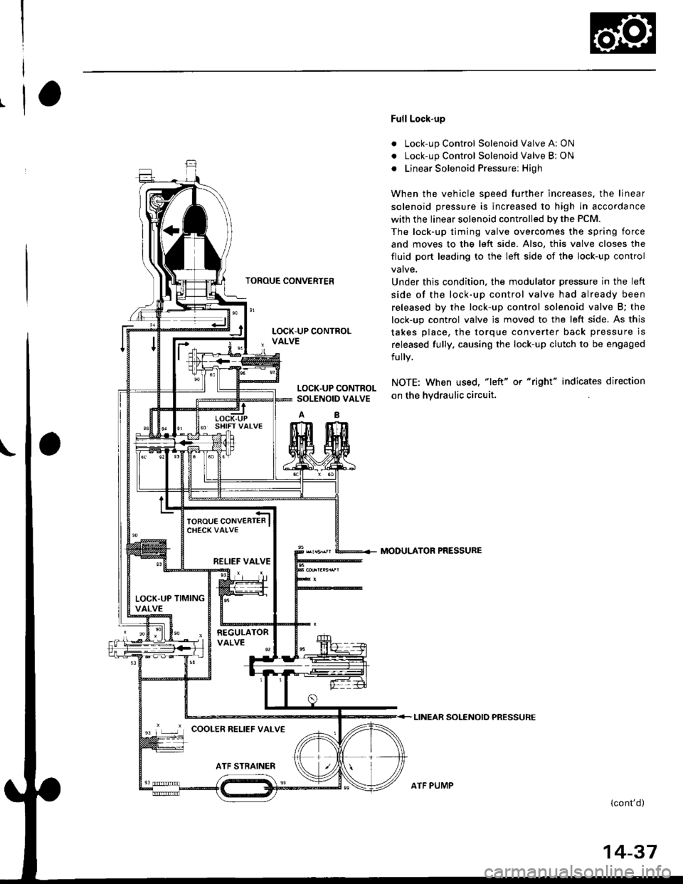
Full Lock-up
. Lock-up Control Solenoid Valve A: ON
. Lock-up Control Solenoid Valve B: ON
o Linear Solenoid Pressure: High
When the vehicle speed further increases. the linear
solenoid pressure is increased to high in accordance
with the linear solenoid controlled bv the PCM.
The lock-up timing valve overcomes the spring force
and moves to the left side. Also, this valve closes the
fluid port leading to the left side of the lock-up control
Under this condition. the modulator pressure in the left
side of the lock-up control valve had already been
released by the lock-up control solenoid valve B; the
lock-up control valve js moved to the left side. As this
takes place, the torque converter back pressure is
released fully. causing the lock-up clutch to be engaged
fully.
NOTE: When used, "|eft" or "right" indicates direction
on the hvdraulic circuit.
MODULATOR PRESSURE
LINEAR SOLENOIO PRESSURE
{cont'd)
LOCK.UP CONTROLSOLENOID VALVE
RELIEF VALVE
LOCK.UP TIMINGVALVE
'r ,-.r' cooLER RELTEF vALvE
ATF PUMP
14-37
Page 716 of 2189
Description
Lock-up System (cont'dl
TOROUE CONVERTER
Deceleration Lock-up
. Lock-up Control Solenoid Valve A: ON. Lock-up Control Solenoid Valve B: Duty Operation
OFF - ONa Linear Solenoid Pressure: Low
The PCM switches solenoid valve B on and off rapidly
under certain conditions. The slight lock-up and half
lock-up regions are maintained so as to lock the torque
converter properly.
NOTE: When used, "left" or "right" indicates direction
on the hydraulic circuit,
MOOULATOR PRESSURE
LINEAR SOLENOID PRESSURE
LOCK-UP CONTROLSOLENOID VALVE
RELIEF VALVE
LOCK.UP TIMINGVALVE
COOLER RELIEF VALVE
ATF STRAINER
1434
ATF PUMP
Page 726 of 2189

Troubleshootin g Procedures
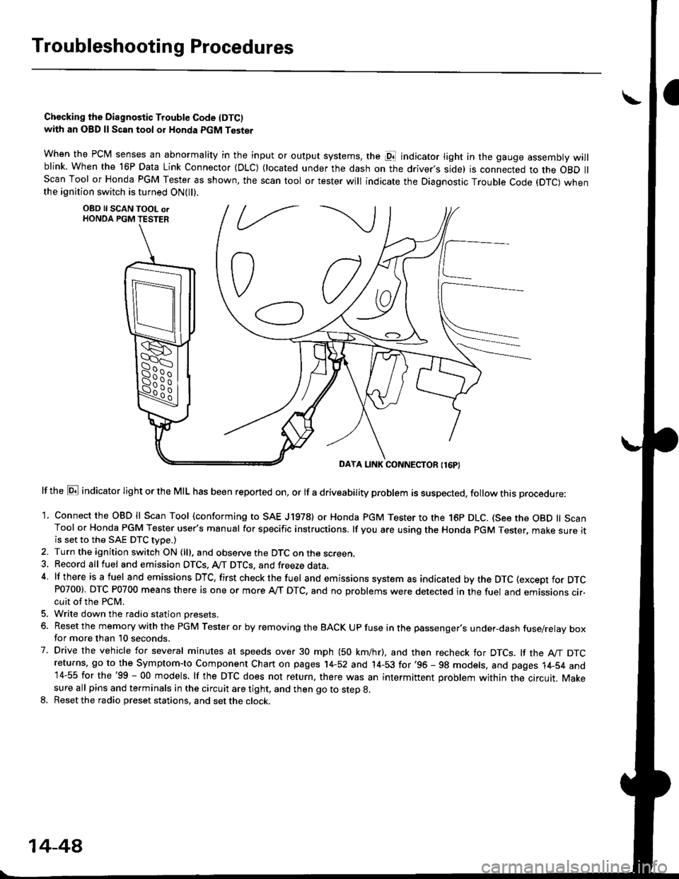
Chccking the Diagnostic Trouble Code IDTC)with an OBD ll Scan tool or Honda PGM Tester
when the PCM senses an abnormality in the input or output systems, the pl indicator light in the gauge assembly willblink. When the 16P Data Link Connector (DLC) (located under the dash on the driver,s side) is connected to the OBD llScan Tool or Honda PGM Tester as shown, the scan tool or tester will indicate the Diagnostic Trouble Code (DTC) whenthe ignition switch is turned ON{ll).
lf the El indicator light or the MIL has been reported on, or lf a driveability problem is suspected, follow this procedure:
1. Connect the OBD ll Scan Tool (conforming to SAE J19781 or Honda PGM Tester to rhe 16p DLC. (See the OBD ll ScanTool or Honda PGM Tester user's manual for specific instructions. lf you are using the Honda PGM Tester, make sure itis set to the SAE DTC type.)
2. Turn the ignition switch ON (lll, and observe the DTC on the screen,3, Record all fuel and emission DTCS, A/T DTCS, and freeze data.4 lf there is a fuel and emissions DTC, first checkthe fuel and emissions system as indicated bythe DTC (except for DTCP0700). DTC P0700 means there is one or more A,/T DTC, and no problems were detected in the fuel and emissions cir-cuit of the PCM.
5. Write down the radio station oresets.
6. Reset the memory with the PGM Tester or by removing the BACK UP fuse in the passenger's under-dash fuse/relay boxfor more than 10 seconds.
7. Drive the vehicle for several minutes at speeds over 30 mph (50 km/hr), and then recheck for DTCS. lf the A"/T DTCreturns, go to the Symptom-to Component Chart on pages 14-52 and 14-53 for'96 - 98 models, and pages 14-54 and14-55 for the'99 - 00 models, lf the DTC does not return, there was an intermittent problem within the circuit. Makesure all pins and terminals in the circuit are tight, and then go to step g.
8. Reset the radio preset stations, and set the clock.
OBD ll SCAN TOOL orHONDA PGM TESTER
DAYA LINK CONNECTOR {16P}
14-44
Page 728 of 2189
Troubleshooting Procedures
1.
2.
(cont'dl
Remove the kick panel on the passenger's side {see section 20}.
Remove the PCM. and turn the PCM over.
Inspect the circuit on the PCM according to the troubleshooting flowchart with the spocial tools and a digital multime-ter as shown.
How lo Use tha Backprobe Set
Connect the backprobe adapters to the stacking patch cords, and connect the cords to a multimeter. Using the wireinsulation as a guide for the contoured tip of the backprobe adapter, gently slide the tip into the connector from thewire side until it comes in contact with the terminal end ofthe wire.
BACKPROSE
BACKPROBE SET07saz - (xtl(xtoA
{two required)
DIGITAL MULNMEIER(Comm€rcially 6vailabl€l-aHM-32-003
t..
14-50
or equival€nt
Page 745 of 2189
From page 14-66
Check Shift Conlrol Sol€noidvalve B tor a Short Circuit:1. Disconnect the 2P connectortrom the shift control solenoidvalve assembly.2. Check for continuity betweenthe 811 and Ag or A22 termi-nals,
Replir shon to ground in th€ wirebetwe.n the 811 terminal and the3hift control solenord valvo B.ls there continuity?
Measure Shift Control Solenoidvrlve B Resistance at the Sole-noid Connector:Measure the resistance betweenthe No.2 terminalofthe shift control solenoid connector and bodyground.
Check tor ooen in the wirebetw..n thc 81 1 t€tminal ard thashift control solonoid vrlv6 B.ls the resistance 12 25 O?
, 2 ll r . 5
PCM CONNECTORS
Wire side of female terminals
SHIFT CONTROL SOLENOID
CONNECTOR
GRN/WHT
Terminal side ol male terminals
14-67
Page 746 of 2189

Electrical Troubleshooting ('gO - 98 Modelsl
Troubleshooting Flowchart - Countershaft Speed Sensor
Po$iblo Causa
' Loosg or laulty conncctionbotwocn tho PCM and c.i hrr-n1't!' Disconnoctad countorahottlpo€{ san3or oonnoctot. Short or opon in countorshaftspeed lonsor wire. F ulty counte.lhalt spe6d s6n-sol
COUNTERSHAFT SPEED SENSORCONNECTOR
lFI,]1-F=r
9l
L_l
Terminal side ol male terminals
PCM CONNECTOR B I25P}
1
l'
NOTE; Record allfreeze data before you troubleshoot.
. OBO ll Scln Tool indicat6 Codem7z).. S6lt-dirgnosis E indic.tollight blink! nin. tim6,
ls the countershaft spoed sensorinstalled properly?
Moa3ure CountoEhaft Sp€ed S6n-sor Reaktanc€ at tho Son3or Con-noctor1. Disconnect the 2P connectortrom the countershaft spgedsensor connector,2. Measure the resistance of thecountershaft sDeed sensor,
ls the resistance 400 - 600 0?
Chock Countersh.ft Spood Scr|3olfor a Shoft Circuit:1. Disconnect the B {25P) connector from the PCM.2. Check for continuity betweenthe body ground and the 823terminal and 822 terminalindividually.
Repai. .hort in th. wiroa b.t$re€ntho 823 lnd 822 torminals .ndlho counteBhaft lpocd aenro..
To page 14-69
4-68
Wire side of temale terminals