Page 319 of 2189
System Description
Electrical Connections ('gg - 00 Models except Dl6y5 engine with M/Tl(cont'd)
CsO5 -r-\- YELI6RN f/ \It P I
'- BLK __1 /
I \'----l
Ft,EL PUMP
EVAP BYPASSSOLENOIDVALVE
ft ti-l
I lJ/c TT__l It.] I c425 __
I LwHr GRN {-l_cnnzwm'_{h\_, IaBAKE StlflTCB
*l : USA mod6l*2: A/T(Di6W, Dt6Y8 engine)*3: CW(DI6Y5 engino)*4: A,rT e16 915y7 "nn,n"*5: ExceB AfT and Dl6Y7 engine,16: Cyr(DI6Y5 €n9ine), D16y8 engine and B,tOA2 engins*7: Dl5Y8, 816A2 engine
Elt^-l'tF'tF q23 r_ c446
I L vever-u - l l-- ,.,- ,.u
t|lL-- cnrzer-rc-{f cnnzar-x,
YEL/GRN
YEVELU
- YEL/GRN- YEVBLU
lr cat'�_ LT GRN2qar/auC- qaN/eud
BLVWHf- BLK/WiT
BLIII- BLul
1 1-50
Page 320 of 2189

System Connectors [Fuel Pumpl
'95 - 98 models, '99 - 00 Dl6Y5 engine with M/T:
ffi
c565
E
c792*r,.'5c793|.,.s
*1r USA mod€l'2: A/T {O16Y7, D16Y8 ensine}13: CVT {O16Y5 ensin€l*4: A/T ind D16Y7 .ngane*5: ExceFt A/T end D16Y7 engine'6: A/T lDl6Y8 enginel*7: CvT (Dl6Y5 enginoland 016Yg engine'8: ,96 Dl6YB engine {coupe),'97 Dl6Y8 sngine
{coupe: sll models, s€d.nr KL modell,'98 Dl5Y5.ngine,'98 D16Y7 engine,'99 - OO Dl6Y5 (M/Tl enginer9: D16Y5 onginet10: M/T {D15Y5 ensinelr1t: ExceDt M/T (D16Y5 engine)tl2: D16Y5, Dl6Yg engine*13: Dl6Y8 enginer14: D16Y7 engine*15:'97 Dl6Y7 ensine {coupe: KL model, sodan:
KL (LX) modeu,'98 Dt6Y7 engine
NOTE: . Different wires with the same color have been given a number suffix to distinguish them (for example' YEUBLK1
and YEVBLK'� are not the samel.
. O: Related to Fuel and Emissions System'
. - Connector with male terminals (dou ble outline): View f rom term inal side
- Connector with female terminals (single outline): View from wire side
c7931...15
ffi
1 1-51
Page 331 of 2189
System Description
System Connectors lDash and Floorl (contd)
'96 - 98 models,'99 - 00 Dl6Y5 engine with M/T:
(
c432*13
11-62
Page 333 of 2189
System Description
System Connectors IEngine Compaftment]
'99 - 00 D16Y5 ICVT), D16Y8 engine:
cl14 C142'3
*1: USA model'2: A/T {D16Y7, O16Y8 engine)*3: CVT lD16Y5 engine)*4:A/T and D16Y7 engine*5: Except A/T and D16Y7 engine*6: CVT {D16Y5 engine).O16YB engin€ and816A2 engine*7: D'|6Y8, 81642 engine
11-64
Page 345 of 2189
System Description
a
a
a
System Connectors [Dash and Floor]
('99 - fil models except D16Y5 engine with M/Tl
L
11-76
L
Page 349 of 2189
System Descriptions
System Connectors lFuel Pump]
('9!, - 00 models 6xcept Dl6Y5 ongino with M/T)
\(
I
c568
ffi
c565
E
c792
Different wires with the same color have been given a number suffix to distinguish them (for example, YEUBLKIand YEVBLK, are not the same).
O: Related to Fuel and Emissions System.- Connector with male terminals (double outline): View from terminal side- Connector with female terminals (single outline): View from wire side
c793
fr
NOTE: o
a
a
1 1-80
Page 352 of 2189
lf the inspection for a particular code requires voltage or resistance checks at the ECM/PCM connectors, remove the right
kick panel. Pull the carpet back to expose the ECM/PCM. Remove the ABS control unit if so equipped. unbolt the EcM/
PCM bolt. Turn the ignition switch oFF, and connect the backprobe sets and a digital multimeter as described below
check the system according to the procedure described for the appropriate code(s) listed on the following pages'
The illustrationshows '96 - '98 models.
How to Use lhe Backprobe Sets
connect the backprobe adapters to the stacking patch cords, and connect the cords to a multimeter. using the wire insula-
tion as a guide for the contoured trp of the backprobe adapter. gently slide the tip into the connector from the wire side
until it comes in contact with terminal end of the wire'
BackProbe
BACKPROEE SET
07SAZ - 001000A lTwo
DIGITAL MULTIMETER(Commercially avail.bleI orKs - AHM - 32 - oo3 (cont'd)
KICK PANEL
1 1-83
Page 353 of 2189

Troubleshooting
Troubleshooting Procedures (cont,dl
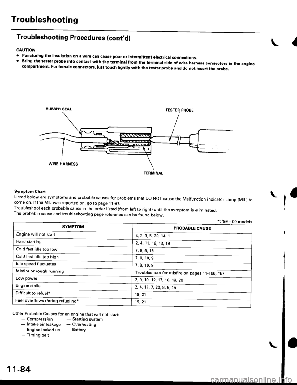
CAUTION:
. Punqturing ihe insulation on a wirs can cause poor or intermiftent electricar connections.I Bring the test€r probe into contacl with the terminatlrom the terminal side of wire harnesg conncctors in the gngin€compartment. For temale connectors, iust touch lightly with the tester probe and do not inse.t the probe.
\I
RUBBER SEAL
Other Probable Causes for an engine that will not start:- Compression- Starting system- lntake air leakage - Overheating- Engine locked up - Battery- Timing belt
TESTER PROBE
Symptom Chart
Listed below are symptoms and probable causes for problems that Do NoT cause the Malfunction indicator Lamp (MlL) tocome on. lfthe MIL was reported on, go to page 11_81.Troubleshoot each probabre cause in the order risted (from reft to right) untir the symptom is eriminated.The probable cause and troubleshooting page reference can be found berow.
L
*: '99 - 00 models
TERMINAL
SYMPTOMPROBABLE CAUSE
4,2,3, 5,20, 14, 1
2, 4, 11, 16, 13, 't9
?, s^6. 16
1,8,10.9
Engine will not sta rt
Hard starting
Cold fast idle too low
Cold fast idle too high
ldle speed fluctuates7,8, 10.9
Troubleshoot for misfire on pages l1-166, 167Misfire or rough running
LOW power
E"g|* "t"lb
2,9, 10, 12, 11, 16, 't8,20
2,4,11,7,20,8,5,15
't9, 21
1r, ,1
Difficult to refuel*
Fuel overflows during refueling*
11-84