Page 995 of 2189
End Cover/lntermediate Housing
Removal
NOTE:
. Cleanall parts in solvent or carburetor cleansr, and drywith compressed air,. Blow out all passages.
. When removing the end cover/intermediate housing, replacs the following parts:- O-rings- End cover gasket- Transmission housing gasket- Sealing rings- Sealing washers
8 x 1 .25 mm BOLT
REVERSE BRAKE
{u
END PLATE
6 x 1.0 mm BOLT
Dtsc
PLATE
DISC SPRING
SNAP
THRUST
END COVERGASXETFeplac€.25x31 mmSelective part
RING GEAR
THRUST WASHER
THRUSI NEEDLEBEARING
THRUST WASHER
CARRIER ASSEMBLY
THRUST WASHER
THRUST NEEDLEBEARING
SUN GEAR
INPUT SHAFT
SNAP RING
CLUTCH ENDPLATE
sNAP /R|NG I
8 x 1.25 mm BOLT
TRANSMISSTONHOUSING GASKETReplace.
DOWEL PIN
INIERMEDIATEHOUSING ASSEMSLY
FORWARD CLUTCHASSEMBLY
SEALING RING (RUBBER}
Replace.
SNAP RING
o.BINGReplace.
SNAP RINGRETAINER
SPRING RETAINER/RETURN SPRINGS
14-318
HOUSING
Page 1005 of 2189
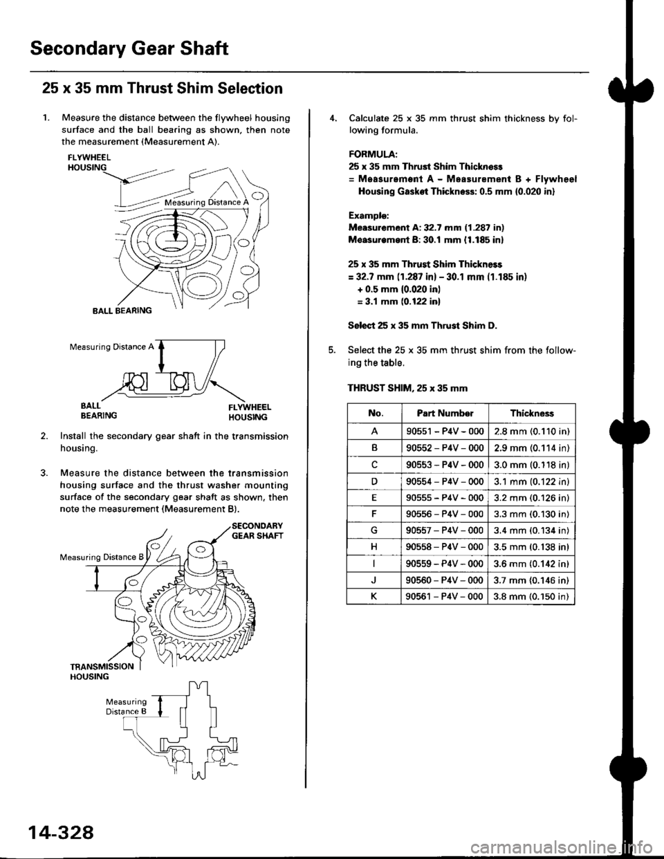
Secondary Gear Shaft
25 x 35 mm Thrust Shim Selection
1. Measure the distance between the flywheel housing
surface and the ball bearing as shown, then note
the measurement (Measurement A).
FLYWHEELHOUSING
>dt?'
BALL BEARING
EALL FLYWHEELBEARING HOUSTNG
Install the secondary gear shatt in the transmission
housing.
Measure the distance between the transmission
housing surface and the thrust washer mounting
surface of the secondary gear shaft as shown, then
note the measurement (Measurement B).
O
Measuring Distance A
BALL
14-328
Calculate 25 x 35 mm thrust shim thickness bv fol-
lowing formula.
FORMULA;
25 x 35 mm Thrust Shim Thicknoss
= Measurement A - Measurement B + Flywheel
Housing Gasket Thickness: 0.5 mm {0.020 in}
Example:
Measurement A: 32.7 mm (1.287 in)
Moasurem.nt B: 30.! mm {1.185 in}
25 x 35 mm Thrust Shim Thickness
= 32.7 mm (1.287 in) - 30.1 mm (1.185 in)
+ 0.5 mm {0.020 in)
= 3.1 mm (0.122 inl
Select 25 x 35 mm Thrust Shim D.
Select the 25 x 35 mm thrust shim from the follow-
ing the table.
THRUST SHIM, 25 x 35 mm
No.Part NumberThickne3s
90551 - P4V - 0002.8 mm (0.110 in)
B90552-P4V-0002.9 mm (0.114 in)
c90553-P4V-0003.0 mm (0.118 in)
D90554-P4V-0003.1 mm (0.122 in)
E90555-P4V-0003.2 mm (0.126 in)
90556-P4V-0003.3 mm (0.130 in)
G90557-P4V-0003.4 mm (0.134 in)
H90558-P4V-0003.5 mm (0.138 in)
90559-P4V-0003.6 mm {0.142 in)
90560-P4V-0003.7 mm (0.146 in)
K90561 - P4V - 0003.8 mm (0.'150 in)
Page 1014 of 2189
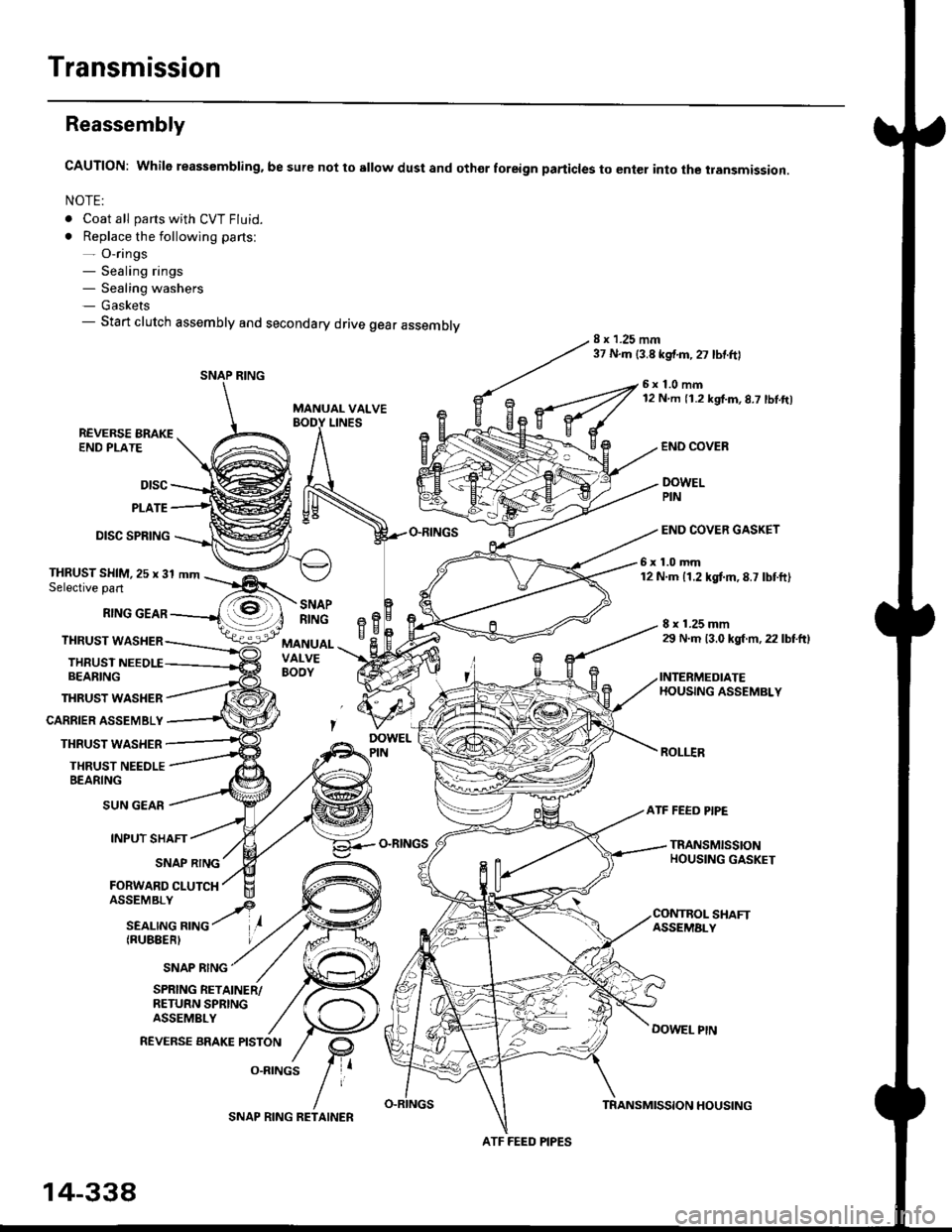
Transmission
Reassembly
CAUTION: While reassembling. be sure not to sllow dust and othor foreign particles to enter into the transmission.
NOTE:
. Coat all parts with CVT Fluid.
. Replace the following parts:- O-rings- Sealing rings- Sealing washers- Gaskets- Start clutch assembly and secondary drive gear assembly8 x 1.25 mm37 N.m {3.8 kgf.m,27 lbtftl
MANUAL VALVE
6x1.0mm12 N m 11.2 kgf.m,8.7 lbl.ft)
LINESREVERSE BRAKEEND PLATE
Dtsc
PLATE
DISC SPRING
THRUST WASHER
CARRIER ASSEMBLY
THRUST WASHER
THRUST NEEDLEBEARING
END COVEB
DOWELPIN
END COVER GASKET
6x1.0mm12 N.m 11.2 kgtm,8.7 lbtft)THRUST SHIM,25 x 31 mmSelective part
RING GEAR
THRUST WASHER
THRUSTBEARING
8 x 1.25 mm29 N.m 13.0 kgl m, 22 lbtftl
INTERMEDIATEHOUSING ASSEMBLY
ROLI.IR
SNAPRINGeBH^cMANUALVALVEBOOY
SUN GEAR
INPUT SHAFT
(RUBEERI
ATF FEED PIPE
O-RINGSTRANSMISSIONHOUSING GASKETSNAP RING
FORWARD CLUTCH
SNAP RING
SHAFTASSEMALY
DOWEL PtN
SPRING RETAINER/RETURN SPRINGASSEMBLY
REVERSE BRAKE PISTON
O.RINGS
SNAP RING
ATF FEED PIPES
14-338
SNAP RING RETAINERTRANSMISSION HOUSING
Page 1015 of 2189
1.
7.
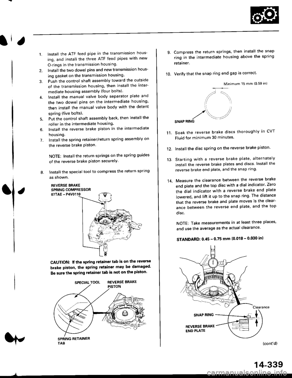
lnstall the ATF feed pipe in the transmission hous-
ing, and install the three ATF feed pipes with new
O-rings in the transmission housing,
Install the two dowel pins and new transmission hous-
ing gasket on the transmission housing.
Push the control shaft assembly toward the outside
of the transmission housing, then install the inter-
mediate housing assembly (four bolts).
lnstall the manual valve body separator plate and
the two dowel pins on the intermediate housing,
then install the rnanual valve body with the detent
spring (five bolts).
Put the control shaft assembly back, then install the
roller in the intermediate housing.
lnstall the reverse brake piston in the intermediate
housing.
Install the spring retainer/return spring assembly on
the reverse brake Piston.
NOTE: Installthe return springs on the spring guides
of the reverse brake piston securely
tnstall the special tool to compress the return spring
as shown.
REVERSE BRAKESPRING COMPRESSOR07TAE - P4V0110
6.
L
1
CAUTION: lf the spring retainer tab is on the reverse
brakc piston, the spring rstainer may be damaged'
Be sure the spring retainer tab is not on the piston'
rp
SPECIALTOOL REVERSEBRAKE
-^
14-339
10.
9.
14.
Compress the return springs, then install the snap
ring in the intermediate housing above the spring
retainer.
Verify that the snap ring end gap is correct'
Mini
/,,- '-t,,,,.
// \i/ ',r
'1 ,
.r' //'/. .-J?RINGSNAP
mum 15 mm 10.59 in)
Soak the reverse brake discs thoroughly in CVT
Fluid for minimum 30 minutes.
Installthe disc spring on the reverse brake piston'
Starting with a reverse brake plate, alternately
install the reverse brake plates and discs lnstall the
reverse brake end plate, and the snap ring'
Measure the clearance between the reverse brake
end plate and the top disc with a dial indicator' Zero
the dial indicator with a reverse brake end plate
lowered, and lift it up to the snap ring The distance
that the reverse brake and plate moves is the clear-
ance between the reverse end plate, and the top
disc.
NOTE: Take measurements in at least three places'
and use the average as the actual clearance'
STANDARD: 0.45 - 0.75 mm (0.018 - 0'030 in)
{cont'd)
11.
12.
13.
Page 1018 of 2189
Transmission
Reassembly (cont'd)
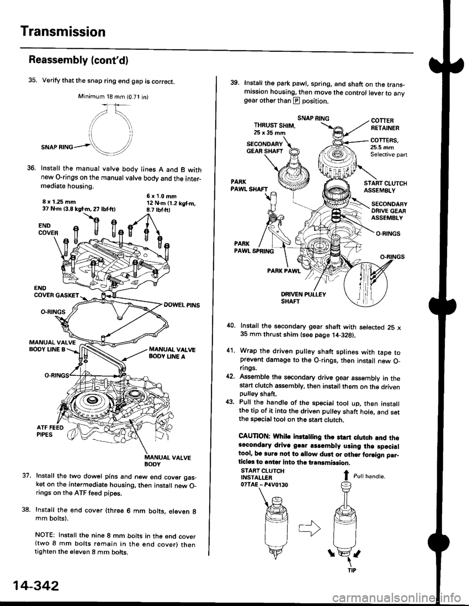
35. Verify that the snap ring end gap is correct.
Minimum 18 mm (0.71 in)
,/\,
."or**ol!/'
Install the manual valve body lines A and B wkhnew O-rings on the manual valve body and the inter-mediate housing.
6x1.0mm12 N..n (1.2 kgt m,8.7 rbtft)
8 x 1.25 mm37 N.m 13.8 kgf.m,27 lbf.ftl
flgENDCOVER
37.
ENDCOVER GASKET
DOWEL PINSO-RINGS
MANUAL VALVEBODY LINE A
uaNYuAL VALVE
Install the two dowel pins and new end cover gas_ket on the intermediate housing, then install new O_rings on the ATF feed pipes.
Install the end cover (three 6 mm bolts, eleven g
mm bolts).
NOTE: Install the nine 8 mm bolts in the end cover(two 8 mm bolts remain in the end cover) thentighten the eleven 8 mm bolts.
14-342
39. Install the park pawl, spring, and shaft on the trans-mission housing, then move the control lever to anvgear other than E position.
THBUST SHIM,25x35mm
SNAP RINGCOTTERRETAINER
COTTERS,25.5 mmSelective pan
START CI.UTCHASSEMBLY
O.RINGS
PARKPAWL SPRING
PARK PAWL
,10, Install the secondary gear shaft with setected 25 x35 mm thrust shim (see page ,14-328).
41. Wrap the driven pulley shaft splines with taDe toprevent damage to the O-rings, then install new O_rings.
42, Assemble ths secondary drive goar assembly in thestart clutch assembly, then installthem on the drivenpulley shaft,
43. Pull the handle of the special tool up, then installthe tip of it into the driven pulley shaft hole, and setthe special tool on the stan clutch.
CAUTION: Whib in3trling thc st rt ctutch and rh.3ocondlry driye g.!r a3sombly using lh€ specialtool, bo 3urc nol to sllow du3t or olher foraign par_ticlos to ontq into tho iransmbsion.
I c,rr r,unar".
SECONDARYGEAR SHAFT
START CLUTCHINSTALLER07TAE - P4V0r30
SECONDARYORIVE GEAFASSEMBLY
Page 1021 of 2189
l.
60. Install the ditferential assembly
61. Installthe ATF passage line assembly with new O-rings (one boltl'
62. Install thethreedowel pinsand new flywheel housing gasket on the transmission housing'
63. Install the flywheel housing and connector bracket (twenty bolts)'
64. Installthe ATF passage line holder assembly (two bolts)'
8 x 1.25 mm29 N.m t3.o kg['m, 22 lbf'ttl
IATF PASSAGE L|NE I"o.o.'o{
d
rm
\A
o-nrnc--.-..ff
FLYWHEEL HOUSINGGASKET
6x1.0mm12 N.m {1.2 ksf'm,
8.7 tbf.ftl/g
ugs llFLYWHEEL HOUSING
CONNECTOR BRACKET
DOWEL PIN
DIFFERENNAL ASSEMBLY
DOWEL PIN
ATF PASSAGE LINE
ASSEMALY
6x1.0mm12 N.m 11.2 kgd'm,
8.7 tbr.tr)
O.RING
DOWEL PIN
TRANSMISSIONItousrNG
ATF PASSAGELINE ASSEMBLY
PASSAGE LINEGUIOE
(cont'd)
TRANSMISSION HOUSING
14-345
Page 1022 of 2189
Transmission
Reassembly (cont'dl
65 lnstall the solenoid harness connector with a new O-ring (one bolt), then install the lower valve body assembly withthree dowel pins (eight bolts).
66. Install the ATF strainer with a new O-ring (two bolts).
67. lf necessary, assemble the ATF pan, ATF filter, and the ATF cooler inlet line (see page 14_303).
68. Install the ATF pan with the two dowel pinsand a new ATF pan gasket (fourteen bolts).
69. Install the ATF cooler inlet line bracket bolt.
70. Installthe ATF cooler outlet line with the line bolt and new sealing washers.
6x1.0mm12 N.m 11.2 kgf.m,8.7 rbtft)DOWEL PINS
ATF STRAINER
DOWEL PINS
ATF PAN,/ATF FILTER/ATF COOLER INLETLINE ASSEMELY
@
@
C4
CONNECTOE
6x1.0mm12 N.m {1.2 kgf.m,8.7 tbtftl6x1.0mm12Nm11.2kgl.m,8.? tbf.ft)
LOWER VALVE BODYASSEMBLY
6x1.0mm12 N.m 11.2 kgf.m,8.7 tbt.ft)
ATF COOI.ER INI.ITLINE BRACKET BOLTI x 1.25 mm26 N.m (2.7 kgt.m, 20 lbf.ft)
ATF COOLER OUTI.IT LINE
14-346
Page 1025 of 2189
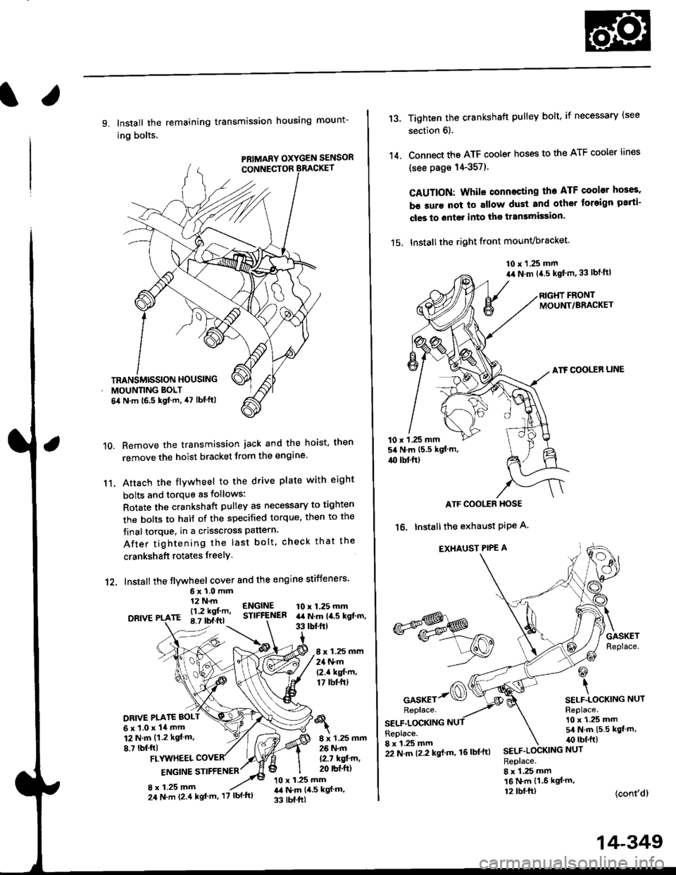
l.
9. Install the remaining transmission housing mount-
ing bolts.
PRIMARY OXYGEN SENSOR
Remove the transmission jack and the hoist. then
remove the hoist bracket from the engine'
Attach the flvwheel to the drive plate with eight
bolts and torque as follows:
Rotate the crankshaft pulley as necessary to tighten
rhe bolts to half of the specified torque, then to the
final torque, in a crisscross pattern.
After tightening the last bolt. check that the
crankshaft rotates freelY.
10.
11.
12. Install the flywheel cover and the engine stiffeners
DRIVE
6xl.0mm12 N.m
- l12 kgf'm'rE 8.7 tbf.ftl
ENGINESTIFfENEB10 x 1.25 mmart N.m la.s kgt.m,33 tbtftt
8 x 1.25 mm24 N.m(2.1 kgf'm,17 tbt.ftt
DRIVE PI.ATE BOLT
6x1.0x14mm12 N.m {1.2 kgt m.
8.7 lbf,ftl8 x 1.25 mm26 N.m
12.7 kqfin,20 rbt'ftlFLYUTHEEL
ENGINE STIFFENER
8 x 1.25 mm10 x 1.25 mmr,a N.m {4,5 kgf m,
33 tbf.ftl
TRANSMISSION HOUSING
MOUNNNG BOLT
6il N.m {6.5 kgf.m, 47 lbf'ftl
24 N.m (2.4 kgt'm, '17 lbf'ftl
22 N.m t2.2 kgl m, 16lbf'ftl
14-349
13.
14.
Tighten the crankshaft pulley bolt, if necessary (see
section 6).
Connect the ATF cooler hoses to the ATF cooler lines
(see page 14-357).
CAUTION: Whilo connecting the ATF cooltr hGes,
b€ sure not lo allow dust and other loreign parti-
cles to entg. into the transmission.
15. Installthe right front mounvbracket'
10 x 1.25 mm
a,r N.m {4.5 kgf'm,33 lbt ftl
RIGHT FRONTMOUNT/BRACKET
ATF COOLER LINE
10 x 1 .25 mm54 N.m {5.5 kgt'm,
4{) tbl.ftt
ATF COOI,TR HOSE
16. Installthe exhaust PiPe A.
EXHAUST PIPE A
GASKETReplace.
@
\SELF.LOCKING NUTReplace.10 x 1.25 mm5/a N.m {5.5 kgt m,irc lbf.ft)
(cont'dl
*s$o
oor*rr-@Replace.
SELF.LOCKINGReplace.8 x 1.25 mmSELF.LOCKING NUT
Replace.8 x 1.25 mm16 N.m {1.6 kgl'm,12 tbl.ftt