Page 129 of 219
either full left or full right to
provide maximum airflow to the
radiator.
If you are driving less than 24 km
(15 miles) at speeds up to 64 km/h
(40 mph) in cold weather, you will
not need to worry about blade
position to provide maximum
airflow.
Transmission operation while
plowing
²Shift transfer case to 4L (4WD
Low) when plowing in small
areas at speeds below 8 km/h
(5 mph).
²Shift transfer case to 4H (4WD
High) when plowing larger areas
or light snow at higher speeds.
Do not exceed 24 km/h
(15 mph).
²Do not shift the transmission
from a forward gear to R
(Reverse) until the engine is at
idle and the wheels are stopped.
²If the vehicle is stuck, shift the
transmission in a steady motion
between forward and reverse
gears. Do not rock the vehicle
for more than a few minutes.
The transmission and tires may
be damaged or the engine can
overheat.
Do not spin the wheels at
over 35 mph (55 km/h).
The tires may fail and injure a
passenger or bystander.
Driving
129
Page 131 of 219
HAZARD LIGHTS CONTROL
Use only in an emergency to warn
traffic of vehicle breakdown,
approaching danger, etc. The
hazard flashers can be operated
when the ignition is off.
²The hazard lights control is
located on top of the steering
column.
²Depress hazard lights control to
activate all hazard flashers
simultaneously.
²Depress control again to turn
the flashers off.
FUEL PUMP SHUT-OFF SWITCH
If the engine cranks but does not
start after a collision, the fuel
pump shut-off switch may have
been activated. The shut-off switch
is a device intended to stop the
electric fuel pump when your
vehicle has been involved in a
substantial jolt.
1. Turn the ignition switch to the
OFF position.
2. Check the fuel system for leaks.
3. If no fuel leak is apparent, reset
the fuel pump shut-off switch by
pushing in the button on the
switch.
4. Turn the ignition switch to the
ON position. Pause for a few
seconds and return the key to the
OFF position.
Roadside emergencies
131
Page 138 of 219
Fuse/Relay Location Fuse Amp Rating Description
30 30A Radio Noise Capacitor,
Ignition Coil, PCM
Power Diode
31 Ð Not Used
Relay 1 Ð Interior Lamp Relay
Relay 2 Ð Battery Saver Relay
Not Used Ð Not Used
Relay 4 Ð One Touch Down
Relay
Relay 5 Ð ACC Delay Relay
Power distribution box
The power distribution box is
located in the engine
compartment. The power
distribution box contains
high-current fuses that protect
your vehicle's main electrical
systems from overloads.
Always disconnect the
battery before servicing
high current fuses.
Always replace the cover
to the Power Distribution
Box before reconnecting the
battery or refilling fluid
reservoirs.
Roadside emergencies
138
Page 140 of 219
Fuse/Relay Location Fuse Amp Rating Description
4 15A* Rear Air Suspension
(RAS)
5 20A* Horn Relay
6 15A* Radio, Premium Sound
Amplifier, CD Changer
7 15A* Main Light Switch,
Park Lamp Relay
8 30A* Main Light Switch,
Headlamp Relay,
Multi-Function Switch
9 15A* Daytime Running
Lamps (DRL) Module,
Fog Lamp Relay
10 25A* Auxiliary Power
Socket
11 Ð Not Used
12 Ð Not Used
13 Ð Not Used
14 60A**/20A** 4 Wheel Anti-Lock
Brake System
(4WABS)
Module/Ignition Switch
(W/RABS Only)
15 50A** Rear Air Suspension
Compressor
16 40A** Trailer Tow Battery
Charge Relay, Engine
Fuse Module (Fuse 2)
17 30A** Shift on the Fly Relay,
Transfer Case Shift
Relay
18 30A** Power Seat Control
Switch
19 20A** Fuel Pump Relay
Roadside emergencies
140
Page 141 of 219
Fuse/Relay Location Fuse Amp Rating Description
20 50A** Ignition Switch
21 50A** Ignition Switch
22 50A** Junction Box
Fuse/Relay Panel
Battery Feed
23 40A** Blower Relay
24 30A** PCM Power Relay,
Engine Fuse Module
(Fuse 1)
25 30A** Junction Box
Fuse/Relay Panel, ACC
Delay Relay
26 Ð Not Used
27 Ð Not Used
28 30A** Trailer Electronic
Brake Controller
29 Ð Not Used
*Mini fuses **Maxi
fuses
CHANGING THE TIRES
If you get a flat tire while driving,
do not apply the brake heavily.
Instead, gradually decrease your
speed. Hold the steering wheel
firmly and slowly move to a safe
place on the side of the road.
Spare tire information
Your vehicle is equipped with a
spare tire that may be used as a
spare or a regular tire. The spare
tire is not equipped with wheel
trim. The wheel trim from the
original wheel/tire may be used on
the spare.
Roadside emergencies
141
Page 142 of 219

If your vehicle is equipped with
4WD or AWD, a spare tire of a
different size than the road
tires should not be used. Such
a tire could result in damage to
driveline components and make
the vehicle difficult to control.
Location of the spare tire and
tools
The spare tire and tools for your
vehicle are stowed in the following
locations:
Tool Location
Spare tire Under the vehicle, just forward of the
rear bumper
Jack, lug nut wrench Under the seat
Jack handle On top of the radiator support at the
front of the engine compartment
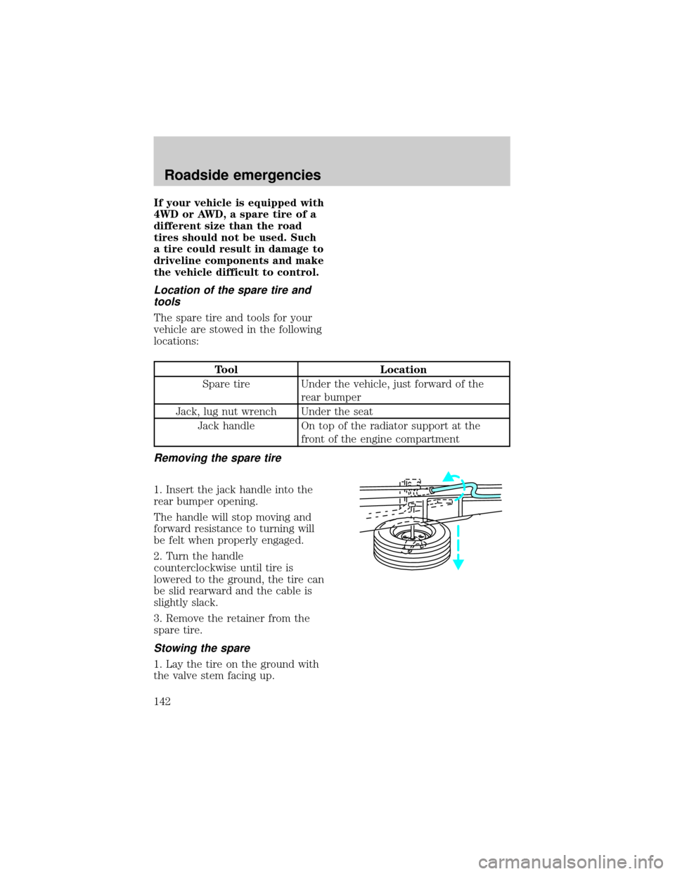
Removing the spare tire
1. Insert the jack handle into the
rear bumper opening.
The handle will stop moving and
forward resistance to turning will
be felt when properly engaged.
2. Turn the handle
counterclockwise until tire is
lowered to the ground, the tire can
be slid rearward and the cable is
slightly slack.
3. Remove the retainer from the
spare tire.
Stowing the spare
1. Lay the tire on the ground with
the valve stem facing up.
Roadside emergencies
142
Page 147 of 219
JUMP STARTING YOUR
VEHICLE
The gases around the
battery can explode if
exposed to flames, sparks, or lit
cigarettes. An explosion could
result in injury or vehicle
damage.
Do not push start your
vehicle. You could damage
the catalytic converter.
Batteries contain sulfuric
acid which burns skin,
eyes, and clothing.
Preparing your vehicle
Also see the label on the battery.
1. Use only a 12±volt supply to
start your vehicle. If you connect
your battery to a 24±volt power
supply you can damage your
starter, ignition system and other
electrical components.
2. Do not disconnect the battery of
the disabled vehicle as this could
damage the vehicle's electrical
system.
3. Park the booster vehicle close to
the hood of the disabled vehicle
making sure theydo nottouch.
Set the parking brake on both
vehicles and stay clear of the
engine cooling fan and other
moving parts.
Roadside emergencies
147
Page 148 of 219

4. Check all battery terminals and
remove any excessive corrosion
before you attach the battery
cables.
5. Turn the heater fan on in both
vehicles to protect any electrical
surges. Turn all other accessories
off.
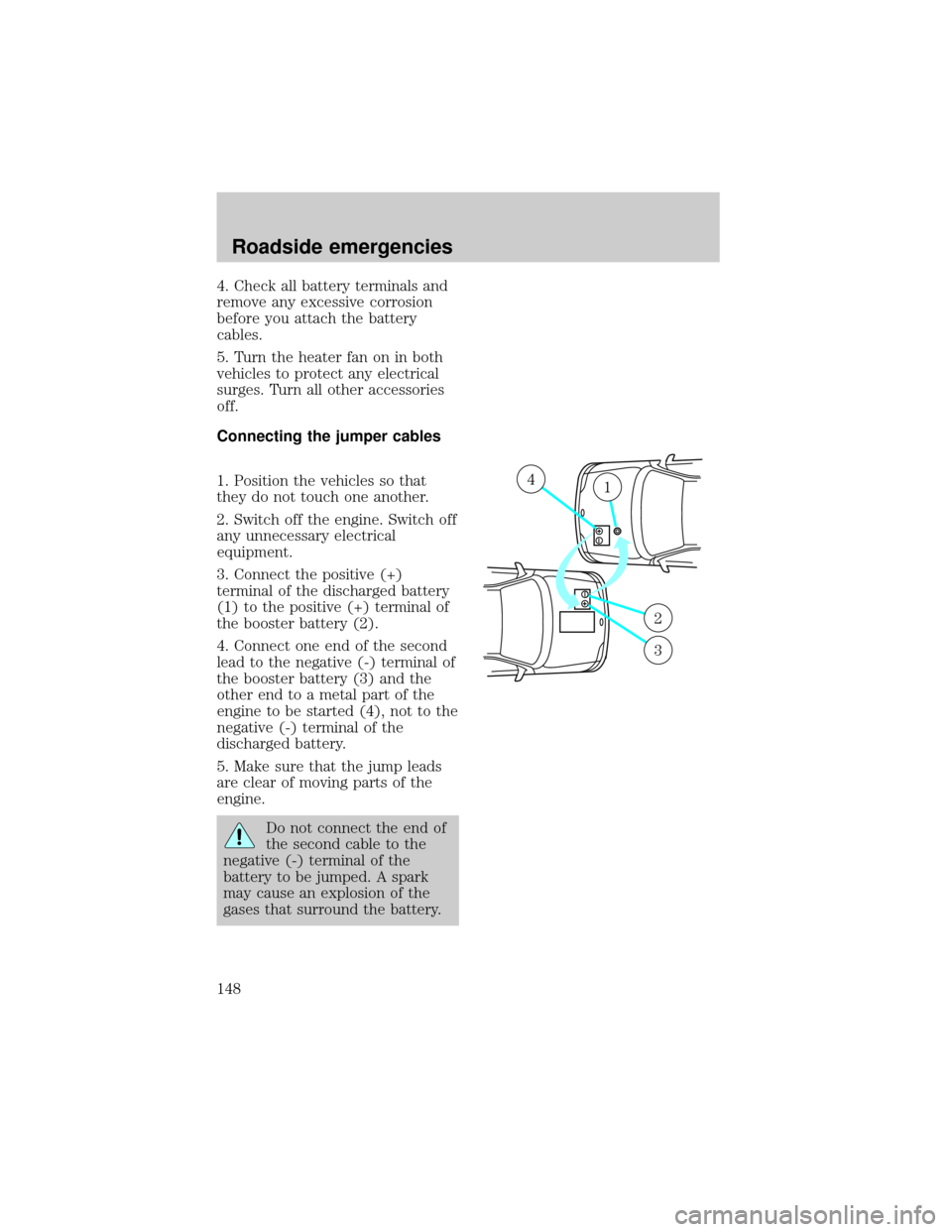
Connecting the jumper cables
1. Position the vehicles so that
they do not touch one another.
2. Switch off the engine. Switch off
any unnecessary electrical
equipment.
3. Connect the positive (+)
terminal of the discharged battery
(1) to the positive (+) terminal of
the booster battery (2).
4. Connect one end of the second
lead to the negative (-) terminal of
the booster battery (3) and the
other end to a metal part of the
engine to be started (4), not to the
negative (-) terminal of the
discharged battery.
5. Make sure that the jump leads
are clear of moving parts of the
engine.
Do not connect the end of
the second cable to the
negative (-) terminal of the
battery to be jumped. A spark
may cause an explosion of the
gases that surround the battery.
+–
+–
41
2
3
Roadside emergencies
148