Page 133 of 219
Always replace a fuse with
one that has the specified
amperage rating. Using a fuse
with a higher amperage rating
can cause severe wire damage
and could start a fire.
Standard fuse amperage rating
and color
Fuse rating Color
5 amp Tan
7.5 amp Brown
10 amp Red
15 amp Light blue
20 amp Yellow
20 amp fuse link Light blue
25 amp Natural
30 amp Light green
30 amp fuse link Pink
40 amp fuse link Green
50 amp fuse link Red
60 amp fuse link Yellow
80 amp fuse link Black
100 amp fuse link Dark blue
Passenger compartment fuse
panel
The fuse panel is located below
and to the left of the steering
wheel by the brake pedal. Pull the
panel cover outward to access the
fuses.
To remove a fuse use the fuse
puller tool provided on the fuse
panel cover.
Roadside emergencies
133
Page 134 of 219
The fuses are coded as follows.
Fuse/Relay Location Fuse Amp Rating Description
1 15A Flasher Relay
2 5A Instrument Cluster
3 25A Cigar Lighter
4 5A Park Lamp Relay,
Headlamp Relay,
Autolamp Module
Remote Anti-Theft
Personality (RAP)
Module, Power Mirror
Switch
FUSE1 RELAY
1
RELAY
2
(NOT
USED)
RELAY
4
RELAY
512 22
21323
31424
4
16 15
25
526
61727
71828
81929
11 21 31930
10 20
Roadside emergencies
134
Page 135 of 219
Fuse/Relay Location Fuse Amp Rating Description
5 15A Digital Transmission
Range (DTR) Sensor
(A/T), Backup Lamp
Switch (M/T), Daytime
Running Lights (DRL)
Module, Speed Control
Servo/Amplifier
Assembly, Heater-A/C
Control Assembly,
Blend Door Actuator
6 5A Shift Lock Actuator,
Generic Electronic
Module (GEM), Rear
Air Suspension (RAS)
Module
7 Ð Not Used
8 5A Radio, Main Light
Switch, Remote
Anti-Theft Personality
(RAP) Module
9 Ð Not Used
10 Ð Not Used
11 30A Washer Pump Relay,
Wiper Run/Park Relay,
Wiper Hi/LO Relay,
Windshield Wiper
Motor
12 5A Data Link Connector
(DLC)
13 15A Rear Anti-Lock Brake
System (RABS)
Module, Brake On/Off
(BOO) Switch, Brake
Pressure Switch
Roadside emergencies
135
Page 136 of 219
Fuse/Relay Location Fuse Amp Rating Description
14 15A Battery Saver Relay,
Interior Lamp Relay
15 5A Generic Electronic
Module (GEM)
16 20A Instrument Cluster
(W/O DRL), Daytime
Running Lamps (DRL)
Module, Hi-Beam
Headlamps (Power
supplied through
Multi-Function
Switch)
17 Ð Not Used
18 5A Park Lamp Relay,
Trailer Electronic
Brake Controller, Main
Light Switch, Trailer
Tow Run Relay, Front
Park/Turn Lamps,
License Lamps,
Stop/Park/Turn Lamps,
Tail/Side Marker
Lamps (Power
supplied through Main
Light Switch)
19 10A Instrument Cluster,
Air Bag Diagnostic
Monitor
20 5A Powertrain Control
Module (PCM),
Generic Electronic
Module (GEM)/Central
Timer Module (CTM)
Roadside emergencies
136
Page 137 of 219
Fuse/Relay Location Fuse Amp Rating Description
21 15A Clutch Pedal Position
(CPP) Switch (W/O
RAP), Starter
Interrupt Relay
(W/RAP)
22 10A Air Bag Diagnostic
Monitor, Passive
De-Activation (PAD)
Module
23 10A Trailer tow Battery
Charge Relay, 4X4
Hub Solenoid, 4X2
Hub Solenoid, Flasher
Relay, Shift on the Fly
Relay
24 10A Blower Relay
25 5A 4 Wheel Anti-Lock
Brake System
(4WABS) Module,
4WABS Relay
26 10A Daytime Running
Lamps (DRL) Module,
Right Headlamp
27 5A Main Light Switch,
Fog Lamp Relay
28 10A Left Headlamp
29 5A Autolamp Module,
Instrument Cluster,
Transmission Control
Switch (TCS), Brake
Warning
Resistor/Diode
Assembly (W/RABS)
Roadside emergencies
137
Page 140 of 219
Fuse/Relay Location Fuse Amp Rating Description
4 15A* Rear Air Suspension
(RAS)
5 20A* Horn Relay
6 15A* Radio, Premium Sound
Amplifier, CD Changer
7 15A* Main Light Switch,
Park Lamp Relay
8 30A* Main Light Switch,
Headlamp Relay,
Multi-Function Switch
9 15A* Daytime Running
Lamps (DRL) Module,
Fog Lamp Relay
10 25A* Auxiliary Power
Socket
11 Ð Not Used
12 Ð Not Used
13 Ð Not Used
14 60A**/20A** 4 Wheel Anti-Lock
Brake System
(4WABS)
Module/Ignition Switch
(W/RABS Only)
15 50A** Rear Air Suspension
Compressor
16 40A** Trailer Tow Battery
Charge Relay, Engine
Fuse Module (Fuse 2)
17 30A** Shift on the Fly Relay,
Transfer Case Shift
Relay
18 30A** Power Seat Control
Switch
19 20A** Fuel Pump Relay
Roadside emergencies
140
Page 142 of 219

If your vehicle is equipped with
4WD or AWD, a spare tire of a
different size than the road
tires should not be used. Such
a tire could result in damage to
driveline components and make
the vehicle difficult to control.
Location of the spare tire and
tools
The spare tire and tools for your
vehicle are stowed in the following
locations:
Tool Location
Spare tire Under the vehicle, just forward of the
rear bumper
Jack, lug nut wrench Under the seat
Jack handle On top of the radiator support at the
front of the engine compartment
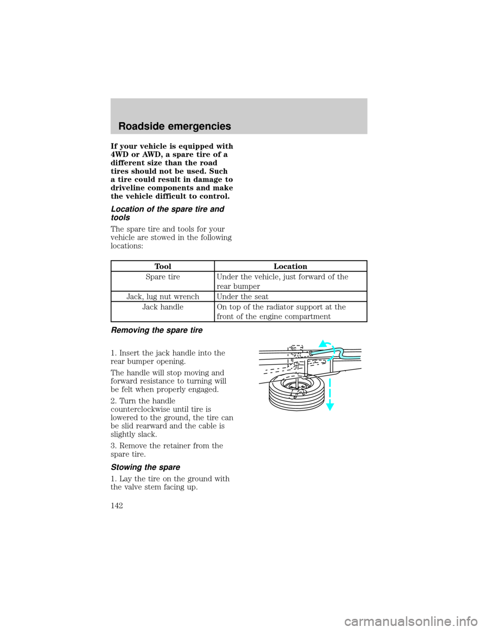
Removing the spare tire
1. Insert the jack handle into the
rear bumper opening.
The handle will stop moving and
forward resistance to turning will
be felt when properly engaged.
2. Turn the handle
counterclockwise until tire is
lowered to the ground, the tire can
be slid rearward and the cable is
slightly slack.
3. Remove the retainer from the
spare tire.
Stowing the spare
1. Lay the tire on the ground with
the valve stem facing up.
Roadside emergencies
142
Page 152 of 219

SERVICE RECOMMENDATIONS
To help you service your vehicle:
²We highlight do-it-yourself items
in the engine compartment for
easy location.
²We provide a ªService Guideº
which makes tracking routine
service easy.
If your vehicle requires
professional service, your
dealership can provide necessary
parts and service. Check your
ªWarranty Guideº to find out which
parts and services are covered.
Use only recommended fuels,
lubricants, fluids and service parts
conforming to specifications.
Motorcraft parts are designed and
built to provide the best
performance in your vehicle.
PRECAUTIONS WHEN
SERVICING YOUR VEHICLE
Be especially careful when
inspecting or servicing your
vehicle.
²Do not work on a hot engine.
The cooling fan is
automatic and may come
on at any time. Always
disconnect the negative terminal
of the battery before working
near the fan.
²When the engine is running, pay
attention loose clothing, jewelry
or long hair do not get caught
up in moving parts.
Maintenance and care
152