Page 4 of 216
10H
C
20304050
60
70
80
90
100
0
0 RPMx1000
F
20•km/h LOW
FUEL
40•6080
100
120 • •
•
•
•140
•123
4
5
CHECK
ENGINE
4 X 4 THEFT6 E18
8
H
L
ABS+ -+ -
0000
00005
0
P
SRS
ON
OFFRES
SET
ACCEL
COAST
Headlamp control
(pg. 20)
Turn signal and
wiper/washer
control
(pg. 38)
Rear window
defroster control
(pg. 22)Instrument cluster
(pg. 6)
Speed control
(pg. 33)Driver side air
bag
(pg. 78)
Instrumentation
4
Page 76 of 216
Safety belt extension assembly
If the safety belt assembly is too
short, even when fully extended,
20 cm (8 inches) can be added to
the safety belt assembly by adding
a safety belt extension assembly
(part number 611C22). Safety belt
extension assemblies can be
obtained from your dealer at no
cost.
Use only extensions manufactured
by the same supplier as the safety
belt. Manufacturer identification is
located at the end of the webbing
on the label. Also, use the safety
belt extension only if the safety
belt is too short for you when fully
extended. Do not use extensions
to change the fit of the shoulder
belt across the torso.
Safety belt warning light and
indicator chime
The seat belt warning light
illuminates in the instrument
cluster and a chime sounds to
remind the occupants to fasten
their safety belts.
Seating and safety restraints
76
Page 82 of 216
If the air bag is inflated,
the air bag will not
function again and must be
replaced immediately.Ifthe
air bag is not replaced, the
unrepaired area will increase the
risk of injury in a collision.
The SRS consists of:
²driver and passenger air bag
modules (which include the
inflators and air bags),
²one or more impact and safing
sensors,
²a readiness light and tone
²and the electrical wiring which
connects the components.
The diagnostic module monitors its
own internal circuits and the
supplemental air bag electrical
system warning (including the
impact sensors), the system wiring,
the air bag system readiness light,
the air bag back up power and the
air bag ignitors.
Determining if the system is
operational
The SRS uses a readiness light in
the instrument cluster or a tone to
indicate the condition of the
system. Refer to theAir bag
readinesssection in the
Instrumentationchapter. Routine
maintenance of the air bag is not
required.
Seating and safety restraints
82
Page 99 of 216

shudder while braking, felt mainly
in the steering wheel, the vehicle
most likely needs service.
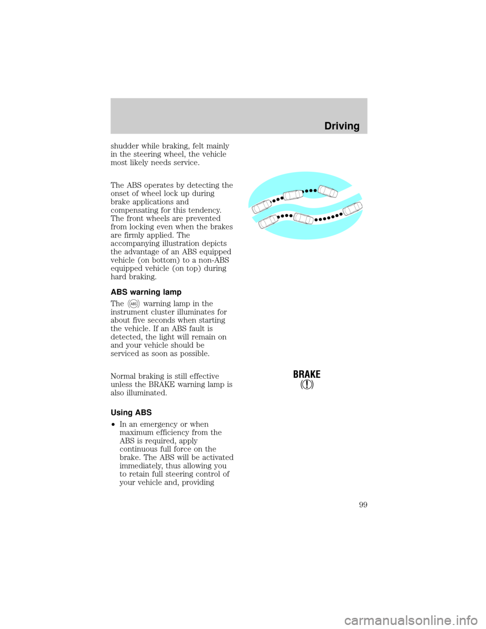
The ABS operates by detecting the
onset of wheel lock up during
brake applications and
compensating for this tendency.
The front wheels are prevented
from locking even when the brakes
are firmly applied. The
accompanying illustration depicts
the advantage of an ABS equipped
vehicle (on bottom) to a non-ABS
equipped vehicle (on top) during
hard braking.
ABS warning lamp
The
ABSwarning lamp in the
instrument cluster illuminates for
about five seconds when starting
the vehicle. If an ABS fault is
detected, the light will remain on
and your vehicle should be
serviced as soon as possible.
Normal braking is still effective
unless the BRAKE warning lamp is
also illuminated.
Using ABS
²In an emergency or when
maximum efficiency from the
ABS is required, apply
continuous full force on the
brake. The ABS will be activated
immediately, thus allowing you
to retain full steering control of
your vehicle and, providing
!
BRAKE
Driving
99
Page 100 of 216
there is sufficient space, will
enable you to avoid obstacles
and bring the vehicle to a
controlled stop.
²We recommend that you
familiarize yourself with this
braking technique. However,
avoid taking any unnecessary
risks.
Parking brake
Apply the parking brake whenever
the vehicle is parked. To set the
parking brake, press the parking
brake pedal down until the pedal
stops.
The BRAKE warning lamp in the
instrument cluster illuminates and
remains illuminated (when the
ignition is turned ON) until the
parking brake is released.
Always set the parking
brake fully and make sure
that the gearshift is securely
latched in P (Park).
BRAKE
HOOD
!
BRAKE
Driving
100
Page 127 of 216

HAZARD LIGHTS CONTROL
Use only in an emergency to warn
traffic of vehicle breakdown,
approaching danger, etc. The
hazard flashers can be operated
when the ignition is off.
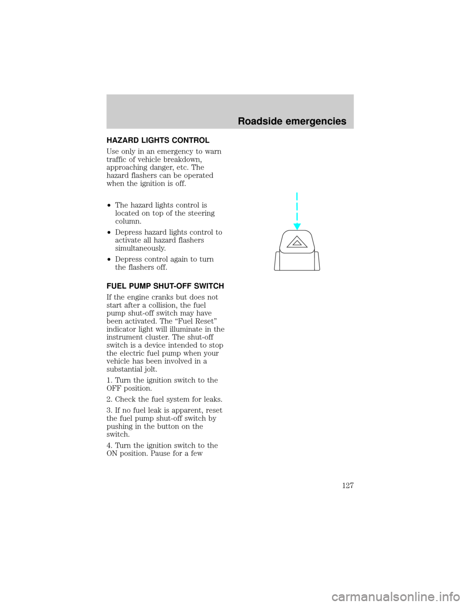
²The hazard lights control is
located on top of the steering
column.
²Depress hazard lights control to
activate all hazard flashers
simultaneously.
²Depress control again to turn
the flashers off.
FUEL PUMP SHUT-OFF SWITCH
If the engine cranks but does not
start after a collision, the fuel
pump shut-off switch may have
been activated. The ªFuel Resetº
indicator light will illuminate in the
instrument cluster. The shut-off
switch is a device intended to stop
the electric fuel pump when your
vehicle has been involved in a
substantial jolt.
1. Turn the ignition switch to the
OFF position.
2. Check the fuel system for leaks.
3. If no fuel leak is apparent, reset
the fuel pump shut-off switch by
pushing in the button on the
switch.
4. Turn the ignition switch to the
ON position. Pause for a few
Roadside emergencies
127
Page 130 of 216
The fuses are coded as follows.
Fuse/Relay
LocationFuse Amp
RatingDescription
1 15A Flasher Relay
2 5A Instrument Cluster, Overhead Trip
Computer (OTC) Module
3 25A Cigar Lighter
4 5A Park Lamp Relay, Headlamp
Relay, Autolamp Module, Remote
Anti-Theft Personality (RAP)
Module, Power Mirror Switch
12 22
21323
617 27
718 28
819 29
930
20
31 21 11 10
31424
41525
51626
Roadside emergencies
130
Page 132 of 216

Fuse/Relay
LocationFuse Amp
RatingDescription
16 20A Instrument Cluster (W/O DRL),
Daytime Running Lamps (DRL)
Module, Hi-Beam Headlamps
(Power supplied through
Multi-Function Switch)
17 10A Heated Backlight Switch, Left
Power/Heated Signal Mirror, Right
Power/Heated Signal Mirror
18 5A Main Light Switch, Generic
Electronic Module (GEM),
Instrument Illumination (Power
supplied through Main Light
Switch)
19 10A Instrument Cluster, Air Bag
Diagnostic Monitor
20 5A 4 Wheel Air Suspension (4WAS),
Generic Electronic Module (GEM)
21 15A Digital Transmission Range (DTR)
Sensor, Junction Box Fuse/Relay
Panel (Fuse 20)
22 10A Air Bag Diagnostic Monitor
23 10A Trailer Tow Battery Charge Relay,
4X4 Center Axle Disconnect
solenoid, 4X2 Center Axle
Disconnect Solenoid, Function
Selector Switch, Rear Integrated
Control Panel, Recirculation
Vacuum Solenoid, Auxiliary A/C
Mode Acturator, Auxiliary A/C
Control Module
24 10A Function Selector Switch
25 5A 4 Wheel Anti-Lock Brake System
(4WABS) Module, 4WABS Relay
Roadside emergencies
132