1998 DODGE RAM 1500 check engine light
[x] Cancel search: check engine lightPage 1488 of 2627
(6) Use a drill, a fine grit Flex-hone and a mixture
of equal parts of mineral spirits and SAE 30W engine
oil to de-glaze the bores.
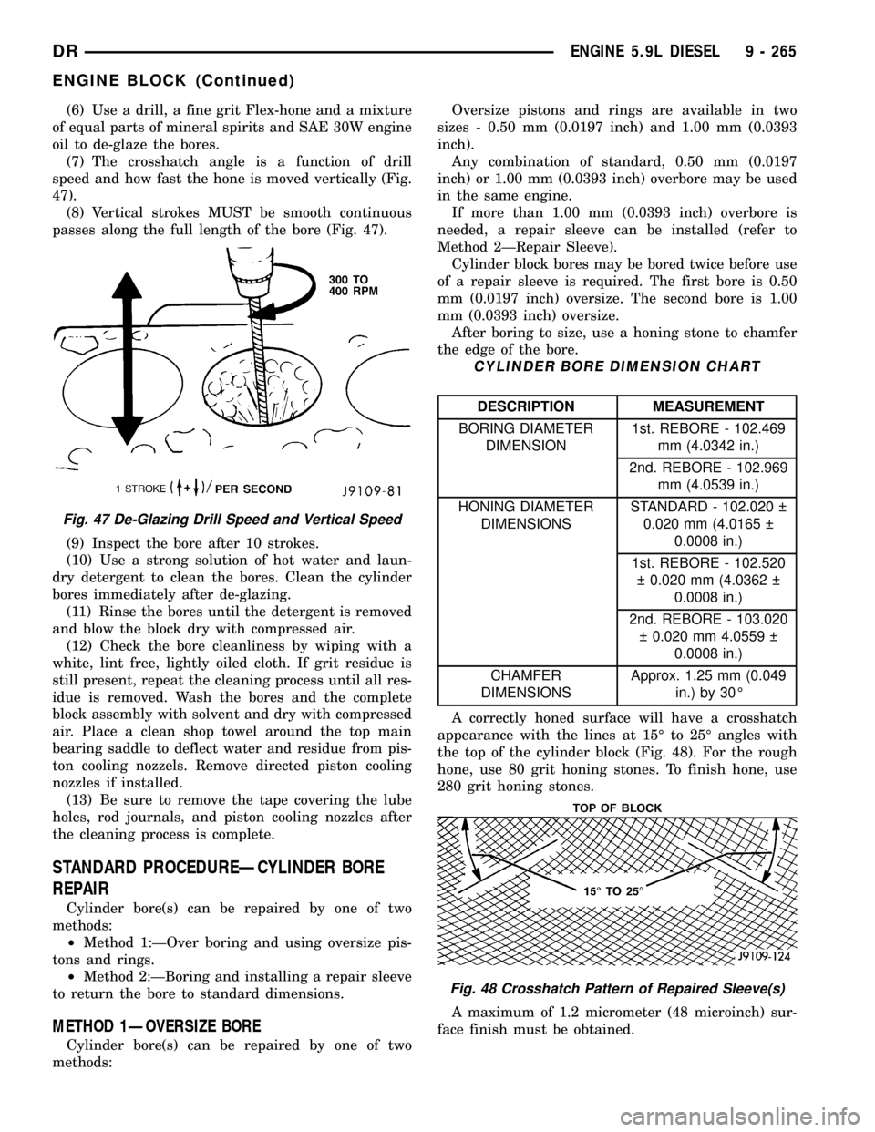
(7) The crosshatch angle is a function of drill
speed and how fast the hone is moved vertically (Fig.
47).
(8) Vertical strokes MUST be smooth continuous
passes along the full length of the bore (Fig. 47).
(9) Inspect the bore after 10 strokes.
(10) Use a strong solution of hot water and laun-
dry detergent to clean the bores. Clean the cylinder
bores immediately after de-glazing.
(11) Rinse the bores until the detergent is removed
and blow the block dry with compressed air.
(12) Check the bore cleanliness by wiping with a
white, lint free, lightly oiled cloth. If grit residue is
still present, repeat the cleaning process until all res-
idue is removed. Wash the bores and the complete
block assembly with solvent and dry with compressed
air. Place a clean shop towel around the top main
bearing saddle to deflect water and residue from pis-
ton cooling nozzels. Remove directed piston cooling
nozzles if installed.
(13) Be sure to remove the tape covering the lube
holes, rod journals, and piston cooling nozzles after
the cleaning process is complete.
STANDARD PROCEDUREÐCYLINDER BORE
REPAIR
Cylinder bore(s) can be repaired by one of two
methods:
²Method 1:ÐOver boring and using oversize pis-
tons and rings.
²Method 2:ÐBoring and installing a repair sleeve
to return the bore to standard dimensions.
METHOD 1ÐOVERSIZE BORE
Cylinder bore(s) can be repaired by one of two
methods:Oversize pistons and rings are available in two
sizes - 0.50 mm (0.0197 inch) and 1.00 mm (0.0393
inch).
Any combination of standard, 0.50 mm (0.0197
inch) or 1.00 mm (0.0393 inch) overbore may be used
in the same engine.
If more than 1.00 mm (0.0393 inch) overbore is
needed, a repair sleeve can be installed (refer to
Method 2ÐRepair Sleeve).
Cylinder block bores may be bored twice before use
of a repair sleeve is required. The first bore is 0.50
mm (0.0197 inch) oversize. The second bore is 1.00
mm (0.0393 inch) oversize.
After boring to size, use a honing stone to chamfer
the edge of the bore.
CYLINDER BORE DIMENSION CHART
DESCRIPTION MEASUREMENT
BORING DIAMETER
DIMENSION1st. REBORE - 102.469
mm (4.0342 in.)
2nd. REBORE - 102.969
mm (4.0539 in.)
HONING DIAMETER
DIMENSIONSSTANDARD - 102.020
0.020 mm (4.0165
0.0008 in.)
1st. REBORE - 102.520
0.020 mm (4.0362
0.0008 in.)
2nd. REBORE - 103.020
0.020 mm 4.0559
0.0008 in.)
CHAMFER
DIMENSIONSApprox. 1.25 mm (0.049
in.) by 30É
A correctly honed surface will have a crosshatch
appearance with the lines at 15É to 25É angles with
the top of the cylinder block (Fig. 48). For the rough
hone, use 80 grit honing stones. To finish hone, use
280 grit honing stones.
A maximum of 1.2 micrometer (48 microinch) sur-
face finish must be obtained.
Fig. 47 De-Glazing Drill Speed and Vertical Speed
Fig. 48 Crosshatch Pattern of Repaired Sleeve(s)
DRENGINE 5.9L DIESEL 9 - 265
ENGINE BLOCK (Continued)
Page 1489 of 2627
After finish honing is complete, immediately clean
the cylinder bores with a strong solution of laundry
detergent and hot water.
After rinsing, blow the block dry.
Check the bore cleanliness by wiping with a white,
lint-free, lightly- oiled cloth. There should be no grit
residue present.
If the block is not to be used right away, coat it
with a rust- preventing compound.
METHOD 2ÐREPAIR SLEEVE
If more than a 1.00 mm (0.03937 inch) diameter
oversize bore is required, the block must be bored
and a repair sleeve installed.
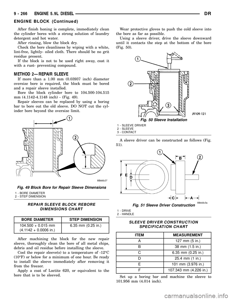
Bore the block cylinder bore to 104.500-104.515
mm (4.1142-4.1148 inch) - (Fig. 49).
Repair sleeves can be replaced by using a boring
bar to bore out the old sleeve. DO NOT cut the cyl-
inder bore beyond the oversize limit.
REPAIR SLEEVE BLOCK REBORE
DIMENSIONS CHART
BORE DIAMETER STEP DIMENSION
104.500 + 0.015 mm
(4.1142 + 0.0006 in.)6.35 mm (0.25 in.)
After machining the block for the new repair
sleeve, thoroughly clean the bore of all metal chips,
debris and oil residue before installing the sleeve.
Cool the repair sleeve(s) to a temperature of -12ÉC
(10ÉF) or below for a minimum of one hour. Be ready
to install the sleeve immediately after removing it
from the freezer.
Apply a coat of Loctite 620, or equivalent to the
bore that is to be sleeved.Wear protective gloves to push the cold sleeve into
the bore as far as possible.
Using a sleeve driver, drive the sleeve downward
until it contacts the step at the bottom of the bore
(Fig. 50).
A sleeve driver can be constructed as follows (Fig.
51).SLEEVE DRIVER CONSTRUCTION
SPECIFICATION CHART
ITEM MEASUREMENT
A 127 mm (5 in.)
B 38 mm (1.5 in.)
C 6.35 mm (0.25 in.)
D 25.4 mm (1 in.)
E 101 mm (3.976 in.)
F 107.343 mm (4.226 in.)
Set up a boring bar and machine the sleeve to
101.956 mm (4.014 inch).
Fig. 49 Block Bore for Repair Sleeve Dimensions
1 - BORE DIAMETER
2 - STEP DIMENSION
Fig. 50 Sleeve Installation
1 - SLEEVE DRIVER
2 - SLEEVE
3 - CONTACT
Fig. 51 Sleeve Driver Construction
1 - DRIVE
2 - HANDLE
9 - 266 ENGINE 5.9L DIESELDR
ENGINE BLOCK (Continued)
Page 1500 of 2627
(7) Install the flywheel or converter drive plate.
Tighten the bolts to 137 N´m (101 ft. lbs.) torque.
(8) Install the clutch cover and disc (if equipped)
(Refer to 6 - CLUTCH/CLUTCH DISC - INSTALLA-
TION).
(9) Install the transmission and transfer case (if
equipped).
(10) Lower vehicle.
(11) Connect battery negative cables.
(12) Check engine oil level and adjust, if necessary.
(13) Start engine and check for oil leaks.
CRANKSHAFT REAR OIL SEAL
RETAINER
REMOVAL
(1) Disconnect the battery negative cables.
(2) Raise vehicle on hoist.
(3) Remove the oil pan drain plug and drain the
engine oil. Re-install plug and torque to 50 N´m (44
ft. lbs.) torque.
(4) Remove transmission and transfer case (if
equipped) from vehicle.
(5)
Remove flywheel or torque converter drive plate.
(6) Disconnect starter cables from starter motor.
(7) Remove starter motor (Refer to 8 - ELECTRI-
CAL/STARTING/STARTER MOTOR - REMOVAL)
and transmission adapter plate assembly.
(8) Remove four (4) oil pan rear bolts. Slide a
feeler gauge between the seal retainer and oil pan
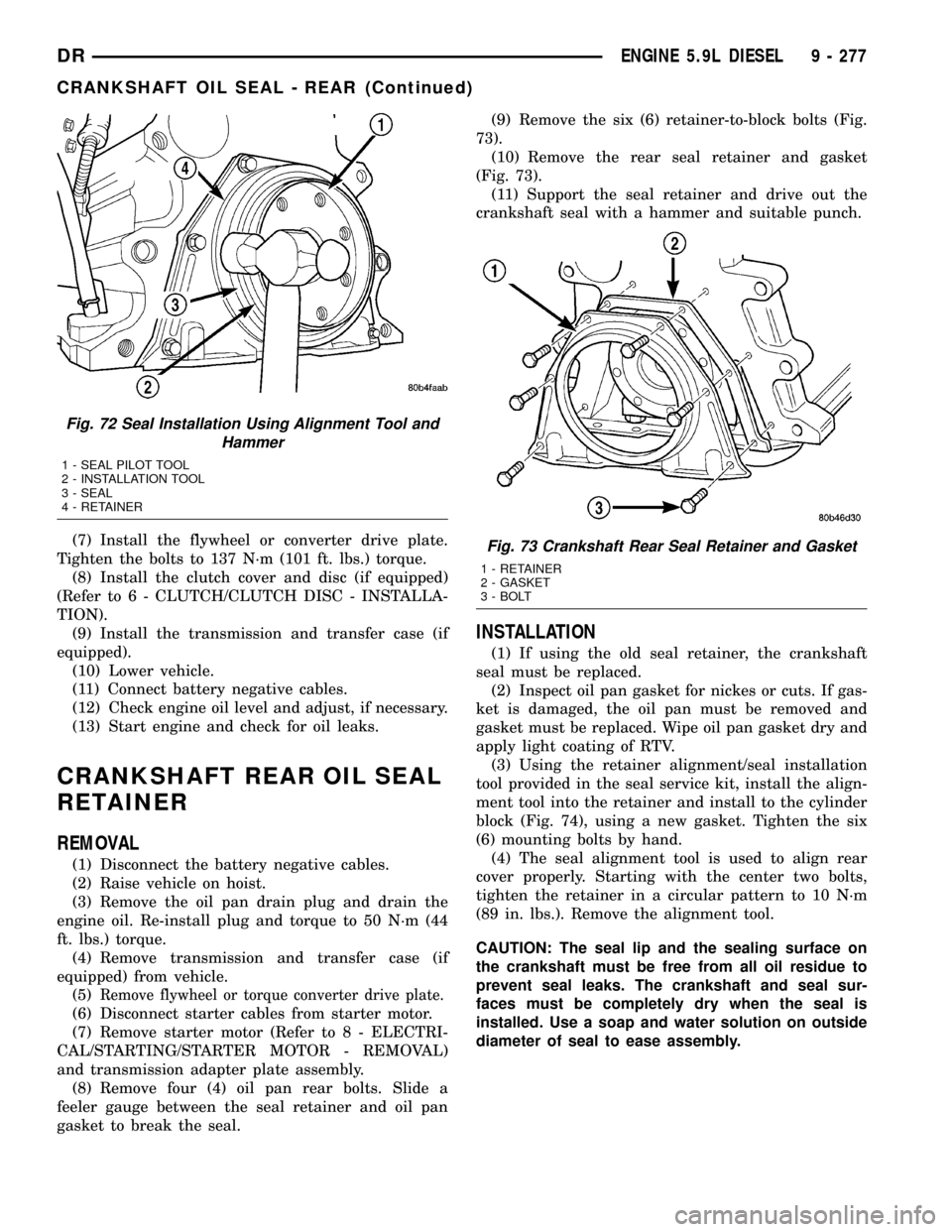
gasket to break the seal.(9) Remove the six (6) retainer-to-block bolts (Fig.
73).
(10) Remove the rear seal retainer and gasket
(Fig. 73).
(11) Support the seal retainer and drive out the
crankshaft seal with a hammer and suitable punch.
INSTALLATION
(1) If using the old seal retainer, the crankshaft
seal must be replaced.
(2) Inspect oil pan gasket for nickes or cuts. If gas-
ket is damaged, the oil pan must be removed and
gasket must be replaced. Wipe oil pan gasket dry and
apply light coating of RTV.
(3) Using the retainer alignment/seal installation
tool provided in the seal service kit, install the align-
ment tool into the retainer and install to the cylinder
block (Fig. 74), using a new gasket. Tighten the six
(6) mounting bolts by hand.
(4) The seal alignment tool is used to align rear
cover properly. Starting with the center two bolts,
tighten the retainer in a circular pattern to 10 N´m
(89 in. lbs.). Remove the alignment tool.
CAUTION: The seal lip and the sealing surface on
the crankshaft must be free from all oil residue to
prevent seal leaks. The crankshaft and seal sur-
faces must be completely dry when the seal is
installed. Use a soap and water solution on outside
diameter of seal to ease assembly.
Fig. 72 Seal Installation Using Alignment Tool and
Hammer
1 - SEAL PILOT TOOL
2 - INSTALLATION TOOL
3 - SEAL
4 - RETAINER
Fig. 73 Crankshaft Rear Seal Retainer and Gasket
1 - RETAINER
2 - GASKET
3 - BOLT
DRENGINE 5.9L DIESEL 9 - 277
CRANKSHAFT OIL SEAL - REAR (Continued)
Page 1516 of 2627
OIL COOLER & LINES
CLEANING
CLEANING AND INSPECTION
Clean the sealing surfaces.
Apply 483 kPa (70 psi) air pressure to the element
to check for leaks. If the element leaks, replace the
element.
OIL FILTER
REMOVAL
(1) Clean the area around the oil filter head.
Remove the filter from below using a cap-style filter
wrench.
(2) Clean the gasket surface of the filter head. The
filter canister O-Ring seal can stick on the filter
head. Make sure it is removed.
INSTALLATION
(1) Fill the oil filter element with clean oil before
installation. Use the same type oil that will be used
in the engine.
(2) Apply a light film of lubricating oil to the seal-
ing surface before installing the filter.
CAUTION: Mechanical over-tightening may distort
the threads or damage the filter element seal.
(3) Install the filter until it contacts the sealing
surface of the oil filter adapter. Tighten filter an
additional
1¤2turn.
OIL PAN
REMOVAL
(1) Disconnect the battery negative cables.
(2) Install engine support fixture # 8534.
(3) Raise vehicle on hoist.
(4) Disconnect starter cables from starter motor.
(5) Remove transmission and transfer case (if
equipped).
(6) Remove flywheel or flexplate.
(7) Remove starter motor (Refer to 8 - ELECTRI-
CAL/STARTING/STARTER MOTOR - REMOVAL)
and transmission adapter plate assembly.
WARNING: HOT OIL CAN CAUSE PERSONAL
INJURY.
(8) Drain the engine oil (Refer to 9 - ENGINE/LU-
BRICATION/OIL - STANDARD PROCEDURE).(9) Install the oil pan drain plug if sealing surface
is not damaged and tighten to 50 N´m (37 ft. lbs.)
torque.
(10) Remove oil pan bolts, break the pan to block
seal, and lower pan slightly and remove oil suction
tube fasteners.
(11) Remove oil pan and suction tube.
CLEANING
Remove all gasket material from the oil pan and
cylinder block sealing surfaces. Extra effort may be
required around T-joint areas. Clean oil pan and
flush suction tube with a suitable solvent.
INSPECTION
Inspect the oil pan, suction tube, and tube braces
for cracks and damage. Replace any defective compo-
nent. Inspect the oil drain plug and drain hole
threads. Inspect the oil pan sealing surface for
straightness. Repair any minor imperfections with a
ball-peen hammer. Do not attempt to repair an oil
pan by welding.
INSTALLATION
(1) Fill the T-joint between the pan rail/gear hous-
ing and pan rail/rear seal retainer with sealant. Use
MopartSilicone Rubber Adhesive Sealant or equiva-
lent.
(2) Place suction tube in oil pan and guide them
into place. Using a new tube to block gasket, install
and tighten the suction tube bolts by hand. Starting
with the oil pump inlet bolts, tighten the bolts to 24
N´m (18 ft. lbs.) torque. Tighten the remaining tube
brace bolts to 43 N´m (32 ft. lbs.) torque.
(3) Starting in the center and working outward,
tighten the oil pan bolts to 28 N´m (21 ft. lbs.)
torque.
(4) Install the flywheel housing assembly with the
starter motor attached and tighten bolts to 77 N´m
(57 ft. lbs.) torque.
(5) Connect starter motor cables.
(6) Install the flywheel or flexplate. Torque to 137
N´m (101 ft. lbs.).
(7) Install transmission and transfer case (if
equipped).
(8) Lower vehicle.
(9) Remove the engine support fixture # 8534.
(10) Install battery negative cables.
(11) Fill the crankcase with new engine oil.
(12) Start engine and check for leaks. Stop engine,
check oil level, and adjust, if necessary.
DRENGINE 5.9L DIESEL 9 - 293
Page 1542 of 2627
CAUTION: Do not apply more than 138 kPa (20 psi)
air pressure to the charge air cooler system, sever
damage to the charge air cooler system may occur.
(3) Connect a regulated air supply to air fitting on
Tool 9022 Adapter. Set air pressure to a Maximum of
138 kPa (20 psi).
(4) Using soapy water check the rubber sleeves,
charge air cooler and intake manifold for leaks.
REMOVAL
WARNING: IF THE ENGINE WAS JUST TURNED
OFF, THE AIR INTAKE SYSTEM TUBES MAY BE
HOT.
(1) Disconnect the battery negative cables.
(2) Discharge the A/C system (Refer to 24 - HEAT-
ING & AIR CONDITIONING/PLUMBING - STAN-
DARD PROCEDURE) and remove the A/C condenser
(Refer to 24 - HEATING & AIR CONDITIONING/
PLUMBING/A/C CONDENSER - REMOVAL) (if A/C
equipped).
(3) Remove the transmission auxiliary cooler
(Refer to 7 - COOLING/TRANSMISSION/TRANS
COOLER - REMOVAL).
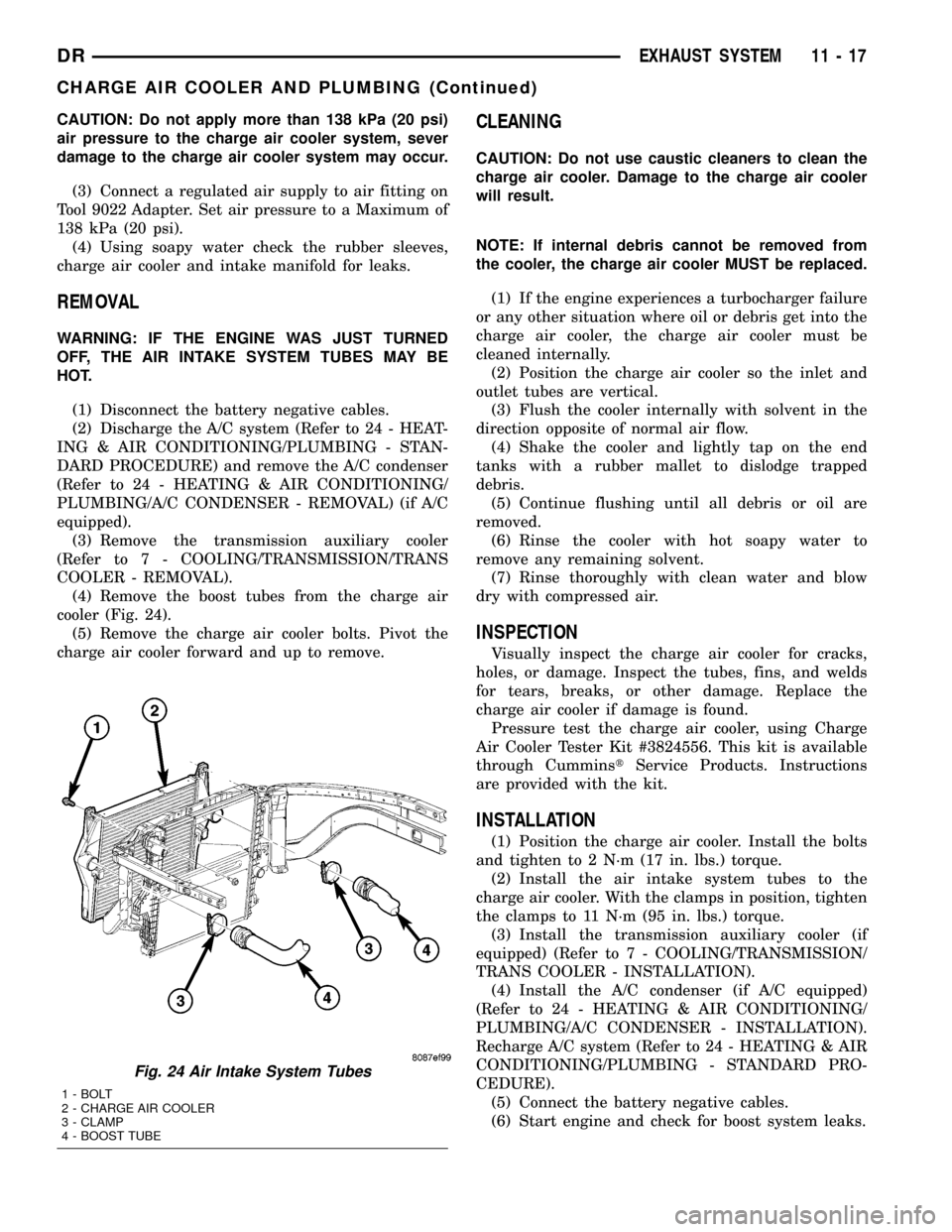
(4) Remove the boost tubes from the charge air
cooler (Fig. 24).
(5) Remove the charge air cooler bolts. Pivot the
charge air cooler forward and up to remove.
CLEANING
CAUTION: Do not use caustic cleaners to clean the
charge air cooler. Damage to the charge air cooler
will result.
NOTE: If internal debris cannot be removed from
the cooler, the charge air cooler MUST be replaced.
(1) If the engine experiences a turbocharger failure
or any other situation where oil or debris get into the
charge air cooler, the charge air cooler must be
cleaned internally.
(2) Position the charge air cooler so the inlet and
outlet tubes are vertical.
(3) Flush the cooler internally with solvent in the
direction opposite of normal air flow.
(4) Shake the cooler and lightly tap on the end
tanks with a rubber mallet to dislodge trapped
debris.
(5) Continue flushing until all debris or oil are
removed.
(6) Rinse the cooler with hot soapy water to
remove any remaining solvent.
(7) Rinse thoroughly with clean water and blow
dry with compressed air.
INSPECTION
Visually inspect the charge air cooler for cracks,
holes, or damage. Inspect the tubes, fins, and welds
for tears, breaks, or other damage. Replace the
charge air cooler if damage is found.
Pressure test the charge air cooler, using Charge
Air Cooler Tester Kit #3824556. This kit is available
through CumminstService Products. Instructions
are provided with the kit.
INSTALLATION
(1) Position the charge air cooler. Install the bolts
and tighten to 2 N´m (17 in. lbs.) torque.
(2) Install the air intake system tubes to the
charge air cooler. With the clamps in position, tighten
the clamps to 11 N´m (95 in. lbs.) torque.
(3) Install the transmission auxiliary cooler (if
equipped) (Refer to 7 - COOLING/TRANSMISSION/
TRANS COOLER - INSTALLATION).
(4) Install the A/C condenser (if A/C equipped)
(Refer to 24 - HEATING & AIR CONDITIONING/
PLUMBING/A/C CONDENSER - INSTALLATION).
Recharge A/C system (Refer to 24 - HEATING & AIR
CONDITIONING/PLUMBING - STANDARD PRO-
CEDURE).
(5) Connect the battery negative cables.
(6) Start engine and check for boost system leaks.
Fig. 24 Air Intake System Tubes
1 - BOLT
2 - CHARGE AIR COOLER
3 - CLAMP
4 - BOOST TUBE
DREXHAUST SYSTEM 11 - 17
CHARGE AIR COOLER AND PLUMBING (Continued)
Page 1554 of 2627
STANDARD PROCEDURE - HYDROFORM
FENDER RAIL REPAIR
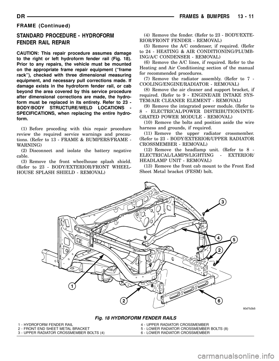
CAUTION: This repair procedure assumes damage
to the right or left hydroform fender rail (Fig. 18).
Prior to any repairs, the vehicle must be mounted
on the appropriate frame repair equipment (ªframe
rackº), checked with three dimensional measuring
equipment, and necessary pull corrections made. If
damage exists in the hydroform fender rail, or cab
beyond the area covered by this service procedure
after dimensional corrections are made, the hydro-
form must be replaced in its entirety. Refer to 23 -
BODY/BODY STRUCTURE/WELD LOCATIONS -
SPECIFICATIONS, when replacing the entire hydro-
form.
(1) Before proceding with this repair procedure
review the required service warnings and precau-
tions. (Refer to 13 - FRAME & BUMPERS/FRAME -
WARNING)
(2) Disconnect and isolate the battery negative
cable.
(3) Remove the front wheelhouse splash shield.
(Refer to 23 - BODY/EXTERIOR/FRONT WHEEL-
HOUSE SPLASH SHIELD - REMOVAL)(4) Remove the fender. (Refer to 23 - BODY/EXTE-
RIOR/FRONT FENDER - REMOVAL)
(5) Remove the A/C condenser, if required. (Refer
to 24 - HEATING & AIR CONDITIONING/PLUMB-
ING/A/C CONDENSER - REMOVAL)
(6) Remove the A/C lines, if required. Refer to the
Heating and Air Conditioning section of the manual
for recommended procedures.
(7) Remove the radiator assembly. (Refer to 7 -
COOLING/ENGINE/RADIATOR - REMOVAL)
(8) Remove the air cleaner and support bracket, if
required. (Refer to 9 - ENGINE/AIR INTAKE SYS-
TEM/AIR CLEANER ELEMENT - REMOVAL)
(9) Remove the integrated power module. (Refer to
8 - ELECTRICAL/POWER DISTRIBUTION/INTE-
GRATED POWER MODULE - REMOVAL)
(10) Remove the bolts and position aside the wire
harness and grounds, if required.
(11) Remove the upper radiator crossmember.
(Refer to 23 - BODY/EXTERIOR/UPPER RADIATOR
CROSSMEMBER - REMOVAL)
(12) Remove the headlamp unit. (Refer to 8 -
ELECTRICAL/LAMPS/LIGHTING - EXTERIOR/
HEADLAMP UNIT - REMOVAL)
(13) Remove the front cab mount to the Front End
Sheet Metal bracket (FESM) bolt.
Fig. 18 HYDROFORM FENDER RAILS
1 - HYDROFORM FENDER RAIL
2 - FRONT END SHEET METAL BRACKET
3 - UPPER RADIATOR CROSSMEMBER BOLTS (4)4 - UPPER RADIATOR CROSSMEMBER
5 - LOWER RADIATOR CROSSMEMBER BOLTS (8)
6 - LOWER RADIATOR CROSSMEMBER
DRFRAMES & BUMPERS 13 - 11
FRAME (Continued)
Page 1585 of 2627
(7) Install 4 fuel rail mounting bolts and tighten.
Refer to torque specifications.
(8) Install 6 ignition coils. Refer to Ignition Coil
Removal/Installation.
(9) Connect electrical connectors to throttle body.
(10) Connect electrical connectors at all fuel injec-
tors. To install connector, refer to (Fig. 17). Push con-
nector onto injector (1) and then push and lock red
colored slider (2). Verify connector is locked to injec-
tor by lightly tugging on connector.
(11) Connect necessary vacuum lines to throttle
body.
(12) Install air resonator mounting bracket near
front of throttle body (2 bolts).
(13) Connect fuel line latch clip and fuel line to
fuel rail. Refer to Quick-Connect Fittings.
(14) Install air box to throttle body.
(15) Install air duct to air box.
(16) Connect battery cable to battery.
(17) Start engine and check for leaks.
4.7L V-8
(1) If fuel injectors are to be installed, refer to Fuel
Injector Removal/Installation.
(2) Clean out fuel injector machined bores in
intake manifold.(3) Apply a small amount of engine oil to each fuel
injector o-ring. This will help in fuel rail installation.
(4) Position fuel rail/fuel injector assembly to
machined injector openings in cylinder head.
(5) Guide each injector into cylinder head. Be care-
ful not to tear injector o-rings.
(6) Pushrightside of fuel rail down until fuel
injectors have bottomed on cylinder head shoulder.
Pushleftfuel rail down until injectors have bot-
tomed on cylinder head shoulder.
(7) Install 4 fuel rail mounting bolts and tighten.
Refer to torque specifications.
(8) Install 8 ignition coils. Refer to Ignition Coil
Removal/Installation.
(9) Connect electrical connectors to throttle body.
(10) Connect electrical connectors at all fuel injec-
tors. To install connector, refer to (Fig. 17). Push con-
nector onto injector (1) and then push and lock red
colored slider (2). Verify connector is locked to injec-
tor by lightly tugging on connector.
(11) Connect necessary vacuum lines to throttle
body.
(12) Install air resonator mounting bracket near
front of throttle body (2 bolts).
(13) Connect fuel line latch clip and fuel line to
fuel rail. Refer to Quick-Connect Fittings.
(14) Install air box to throttle body.
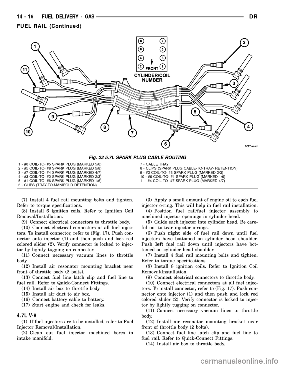
Fig. 22 5.7L SPARK PLUG CABLE ROUTING
1 - #8 COIL-TO- #5 SPARK PLUG (MARKED 5/8) 7 - CABLE TRAY
2 - #5 COIL-TO- #8 SPARK PLUG (MARKED 5/8) 8 - CLIPS (SPARK PLUG CABLE-TO-TRAY- RETENTION)
3 - #7 COIL-TO- #4 SPARK PLUG (MARKED 4/7) 9 - #2 COIL-TO- #3 SPARK PLUG (MARKED 2/3)
4 - #3 COIL-TO- #2 SPARK PLUG (MARKED 2/3) 10 - #6 COIL-TO- #1 SPARK PLUG (MARKED 1/6)
5 - #1 COIL-TO- #6 SPARK PLUG (MARKED 1/6) 11 - #4 COIL-TO- #7 SPARK PLUG (MARKED 4/7)
6 - CLIPS (TRAY-TO-MANIFOLD RETENTION)
14 - 16 FUEL DELIVERY - GASDR
FUEL RAIL (Continued)
Page 1586 of 2627
(15) Install air duct to air box.
(16) Connect battery cable to battery.
(17) Start engine and check for leaks.
5.7L V-8
(1) If fuel injectors are to be installed, refer to Fuel
Injector Removal/Installation.
(2) Clean out fuel injector machined bores in
intake manifold.
(3) Apply a small amount of engine oil to each fuel
injector o-ring. This will help in fuel rail installation.
(4) Position fuel rail/fuel injector assembly to
machined injector openings in intake manifold.
(5) Guide each injector into intake manifold. Be
careful not to tear injector o-rings.
(6) Pushrightside of fuel rail down until fuel
injectors have bottomed on shoulders. Pushleftfuel
rail down until injectors have bottomed on shoulders.
(7) Install 4 fuel rail holdown clamps and 4 mount-
ing bolts. Refer to Torque Specifications.
(8) Position spark plug cable tray and cable assem-
bly to intake manifold. Snap 4 cable tray retaining
clips into intake manifold.
(9) Install all cables to spark plugs and ignition
coils.
(10) Connect electrical connector to throttle body.
(11) Install electrical connectors to all 8 ignition
coils. Refer to Ignition Coil Removal/Installation.
(12) Connect electrical connector to throttle body.
(13) Connect electrical connectors at all fuel injec-
tors. To install connector, refer to (Fig. 17). Push con-
nector onto injector (1) and then push and lock red
colored slider (2). Verify connector is locked to injec-
tor by lightly tugging on connector.
(14) Connect fuel line latch clip and fuel line to
fuel rail. Refer to Quick-Connect Fittings.
(15) Install air resonator to throttle body (2 bolts).
(16) Install flexible air duct to air box.
(17) Connect battery cable to battery.
(18) Start engine and check for leaks.
FUEL TANK
DESCRIPTION
The fuel tank is constructed of a plastic material.
Its main functions are for fuel storage and for place-
ment of the fuel pump module, and (if equipped) cer-
tain ORVR components.
OPERATION
All models pass a full 360 degree rollover test
without fuel leakage. To accomplish this, fuel and
vapor flow controls are required for all fuel tank con-
nections.Two check (control) valves are mounted into the
top of the fuel tank. Refer to Fuel Tank Check Valve
for additional information.
An evaporation control system is connected to the
fuel tank to reduce emissions of fuel vapors into the
atmosphere. When fuel evaporates from the fuel
tank, vapors pass through vent hoses or tubes to a
charcoal canister where they are temporarily held.
When the engine is running, the vapors are drawn
into the intake manifold. Certain models are also
equipped with a self-diagnosing system using a Leak
Detection Pump (LDP) and/or an On-Board Refueling
Vapor Recovery (ORVR) system. Refer to Emission
Control System for additional information.
REMOVAL- EXCEPT DIESEL
Fuel Tank Draining
WARNING: THE FUEL SYSTEM MAY BE UNDER
CONSTANT FUEL PRESSURE EVEN WITH THE
ENGINE OFF. THIS PRESSURE MUST BE
RELEASED BEFORE SERVICING FUEL TANK.
Two different procedures may be used to drain fuel
tank: through the fuel fill fitting on tank, or using
the DRBtscan tool. Due to a one-way check valve
installed into the fuel fill opening fitting at the tank,
the tank cannot be drained conventionally at the fill
cap.
The quickest draining procedure involves removing
the rubber fuel fill hose.
As an alternative procedure, the electric fuel pump
may be activated allowing tank to be drained at fuel
rail connection. Refer to DRB scan tool for fuel pump
activation procedures. Before disconnecting fuel line
at fuel rail, release fuel pressure. Refer to the Fuel
System Pressure Release Procedure for procedures.
Attach end of special test hose tool number 6541,
6539, 6631 or 6923 at fuel rail disconnection (tool
number will depend on model and/or engine applica-
tion). Position opposite end of this hose tool to an
approved gasoline draining station. Activate fuel
pump and drain tank until empty.
If electric fuel pump is not operating, fuel must be
drained through fuel fill fitting at tank. Refer to fol-
lowing procedures.
(1) Release fuel system pressure.
(2) Raise vehicle.
(3) Thoroughly clean area around fuel fill fitting
and rubber fuel fill hose at tank.
(4) If vehicle is equipped with 4 doors and a 6 foot
(short) box, remove left-rear tire/wheel.
(5) Loosen clamp (Fig. 23) and disconnect rubber
fuel fill hose at tank fitting. Using an approved gas
holding tank, drain fuel tank through this fitting.
DRFUEL DELIVERY - GAS 14 - 17
FUEL RAIL (Continued)