1998 DODGE RAM 1500 oil
[x] Cancel search: oilPage 2291 of 2627

STANDARD PROCEDURE
STANDARD PROCEDURE - WHEEL
REPLACEMENT
The wheel studs and nuts are designed for specific
applications. They must be replaced with equivalent
parts. Do not use replacement parts of lesser quality
or a substitute design. All aluminum and some steel
wheels have wheel stud nuts which feature an
enlarged nose. This enlarged nose is necessary to
ensure proper retention of the aluminum wheels.
NOTE: Do not use chrome plated lug nuts with
chrome plated wheels.
Before installing the wheel, be sure to remove any
build up of corrosion on the wheel mounting surfaces.
Ensure wheels are installed with good metal-to-metal
contact. Improper installation could cause loosening
of wheel nuts (Fig. 21). This could affect the safety
and handling of your vehicle.
To install the wheel, first position it properly on
the mounting surface (Fig. 21). All wheel nuts should
then be tightened just snug. Gradually tighten them
in sequence to the proper torque specification, (Fig.
22) (Fig. 23).Never use oil or grease on studs or
nuts.
Wheels must be replaced if they have:
²Excessive runout
²Bent or dented
²Leak air through welds
²Have damaged bolt holes
Wheel repairs employing hammering, heating, or
welding are not allowed.Original equipment wheels are available through
your dealer. Replacement wheels from any other
source should be equivalent in:
²Load carrying capacity
²Diameter
²Width
²Offset
²Mounting configuration
Failure to use equivalent replacement wheels may
affect the safety and handling of your vehicle.
Replacement withusedwheels is not recommended.
Their service history may have included severe treat-
ment.
STANDARD PROCEDURE - DUAL REAR WHEEL
INSTALLATION
Dual rear wheels use a special heavy duty lug nut
wrench. It is recommended to remove and install
dual rear wheels only when the proper wrench is
available. The wrench is also use to remove wheel
Fig. 21 WHEEL INSTALLATION 8-LUG SHOWN
1 - CENTER CAP
2 - LUG NUT
3 - TIRE/WHEEL ASSEMBLY
4 - WHEEL STUDS
Fig. 22 8-LUG TIGHTENING PATTERN
Fig. 23 TYPICAL 6 - LUG NUT TIGHTENING
PATTERN
22 - 12 TIRES/WHEELSDR
WHEELS (Continued)
Page 2292 of 2627
center caps for more information refer to Owner's
Manual.
The tires on both wheels must be completely raised
off the ground when tightening the lug nuts. This
will ensure correct wheel centering and maximum
wheel clamping.
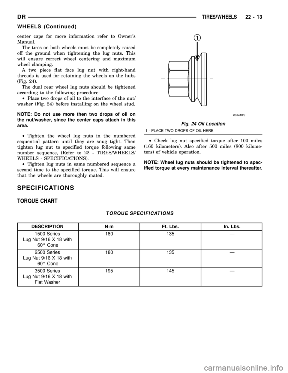
A two piece flat face lug nut with right-hand
threads is used for retaining the wheels on the hubs
(Fig. 24).
The dual rear wheel lug nuts should be tightened
according to the following procedure:
²Place two drops of oil to the interface of the nut/
washer (Fig. 24) before installing on the wheel stud.
NOTE: Do not use more then two drops of oil on
the nut/washer, since the center caps attach in this
area.
²Tighten the wheel lug nuts in the numbered
sequential pattern until they are snug tight. Then
tighten lug nut to specified torque following same
number sequence, (Refer to 22 - TIRES/WHEELS/
WHEELS - SPECIFICATIONS).
²Tighten lug nuts in same numbered sequence a
second time to the specified torque. This will ensure
that the wheels are thoroughly mated.²Check lug nut specified torque after 100 miles
(160 kilometers). Also after 500 miles (800 kilome-
ters) of vehicle operation.
NOTE: Wheel lug nuts should be tightened to spec-
ified torque at every maintenance interval thereafter.
SPECIFICATIONS
TORQUE CHART
TORQUE SPECIFICATIONS
DESCRIPTION N´m Ft. Lbs. In. Lbs.
1500 Series
Lug Nut 9/16 X 18 with
60É Cone180 135 Ð
2500 Series
Lug Nut 9/16 X 18 with
60É Cone180 135 Ð
3500 Series
Lug Nut 9/16 X 18 with
Flat Washer195 145 Ð
Fig. 24 Oil Location
1 - PLACE TWO DROPS OF OIL HERE
DRTIRES/WHEELS 22 - 13
WHEELS (Continued)
Page 2298 of 2627

ROAD TESTING WIND NOISE
(1) Drive the vehicle to verify the general location
of the wind noise.
(2) Apply 50 mm (2 in.) masking tape in 150 mm
(6 in.) lengths along weatherstrips, weld seams or
moldings. After each length is applied, drive the vehi-
cle. If noise goes away after a piece of tape is applied,
remove tape, locate, and repair defect.
POSSIBLE CAUSE OF WIND NOISE
²Moldings standing away from body surface can
catch wind and whistle.
²Gaps in sealed areas behind overhanging body
flanges can cause wind-rushing sounds.
²Misaligned movable components.
²Missing or improperly installed plugs in pillars.
²Weld burn through holes.
STANDARD PROCEDURE
STANDARD PROCEDURE - BODY LUBRICATION
All mechanisms and linkages should be lubricated
when necessary. This will maintain ease of operation
and provide protection against rust and excessive
wear. The weatherstrip seals should be lubricated to
prolong their life as well as to improve door sealing.
All applicable exterior and interior vehicle operat-
ing mechanisms should be inspected and cleaned.
Pivot/sliding contact areas on the mechanisms should
then be lubricated.
(1) When necessary, lubricate the operating mech-
anisms with the specified lubricants.
(2) Apply silicone lubricant to a cloth and wipe it
on door seals to avoid over-spray that can soil pas-
senger's clothing.
(3) Before applying lubricant, the component
should be wiped clean. After lubrication, any excess
lubricant should be removed.
(4) The hood latch, latch release mechanism, latch
striker, and safety latch should be lubricated period-
ically.
(5) The door lock cylinders should be lubricated
twice each year (preferably autumn and spring).
²Spray a small amount of lock cylinder lubricant
directly into the lock cylinder.
²Apply a small amount to the key and insert it
into the lock cylinder.
²Rotate it to the locked position and then back to
the unlocked position several times.
²Remove the key. Wipe the lubricant from it with
a clean cloth to avoid soiling of clothing.
STANDARD PROCEDURE - HEAT STAKING
(1) Remove trim panel.(2) Bend or move the trim panel components at
the heat staked joints. Observe the heat staked loca-
tions and/or component seams for looseness.
(3) Heat stake the components.
(a) If the heat staked or component seam loca-
tion is loose, hold the two components tightly
together and using a soldering gun with a flat tip,
melt the material securing the components
together. Do not over heat the affected area, dam-
age to the exterior of the trim panel may occur.
(b) If the heat staked material is broken or miss-
ing, use a hot glue gun to apply new material to
the area to be repaired. The panels that are being
heat staked must be held together while the apply-
ing the glue. Once the new material is in place, it
may be necessary to use a soldering gun to melt
the newly applied material. Do not over heat the
affected area, damage to the exterior of the trim
panel may occur.
(4) Allow the repaired area to cool and verify the
repair.
(5) Install trim panel.
STANDARD PROCEDURE - PLASTIC BODY
PANEL REPAIR
There are many different types of plastics used in
today's automotive environment. We group plastics in
three different categories: Rigid, Semi-Rigid, and
Flexible. Any of these plastics may require the use of
an adhesion promoter for repair. These types of plas-
tic are used extensively on DaimlerChrysler Motors
vehicles. Always follow repair material manufactur-
er's plastic identification and repair procedures.
Rigid Plastics:
Examples of rigid plastic use: Fascias, Hoods,
Doors, and other Body Panels, which include SMC,
ABS, and Polycarbonates.
Semi-Rigid Plastics:
Examples of semi-rigid plastic use: Interior Panels,
Under Hood Panels, and other Body Trim Panels.
Flexible Plastics:
Examples of flexible plastic use: Fascias, Body
Moldings, and upper and lower Fascia Covers.
Repair Procedure:
The repair procedure for all three categories of
plastics is basically the same. The one difference is
the material used for the repair. The materials must
be specific for each substrate, rigid repair material
for rigid plastic repair, semi-rigid repair material for
semi-rigid plastic repair and flexible repair material
for flexible plastic repair.
DRBODY 23 - 3
BODY (Continued)
Page 2299 of 2627
Adhesion Promoter/Surface Modifier:
Adhesion Promoters/Surface Modifiers are required
for certain plastics. All three categories may have
plastics that require the use of adhesion promoter/
surface modifiers. Always follow repair material man-
ufacturer's plastic identification and repair
procedures.
SAFETY PRECAUTION AND WARNINGS
WARNING:
²EYE PROTECTION SHOULD BE USED WHEN
SERVICING COMPONENTS. PERSONAL INJURY
CAN RESULT.
²USE AN OSHA APPROVED BREATHING MASK
WHEN MIXING EPOXY, GRINDING, AND SPRAYING
PAINT OR SOLVENTS IN A CONFINED AREA. PER-
SONAL INJURY CAN RESULT.²AVOID PROLONGED SKIN CONTACT WITH
RESIN, PETROLEUM, OR ALCOHOL BASED SOL-
VENTS. PERSONAL INJURY CAN RESULT.
²DO NOT VENTURE UNDER A HOISTED VEHI-
CLE THAT IS NOT PROPERLY SUPPORTED ON
SAFETY STANDS. PERSONAL INJURY CAN
RESULT.
NOTE:
²When holes must be drilled or cut in body pan-
els, verify locations of internal body components
and electrical wiring. Damage to vehicle can result.
²Do not use abrasive chemicals or compounds
on undamaged painted surfaces around repair
areas. Damage to finish can result.
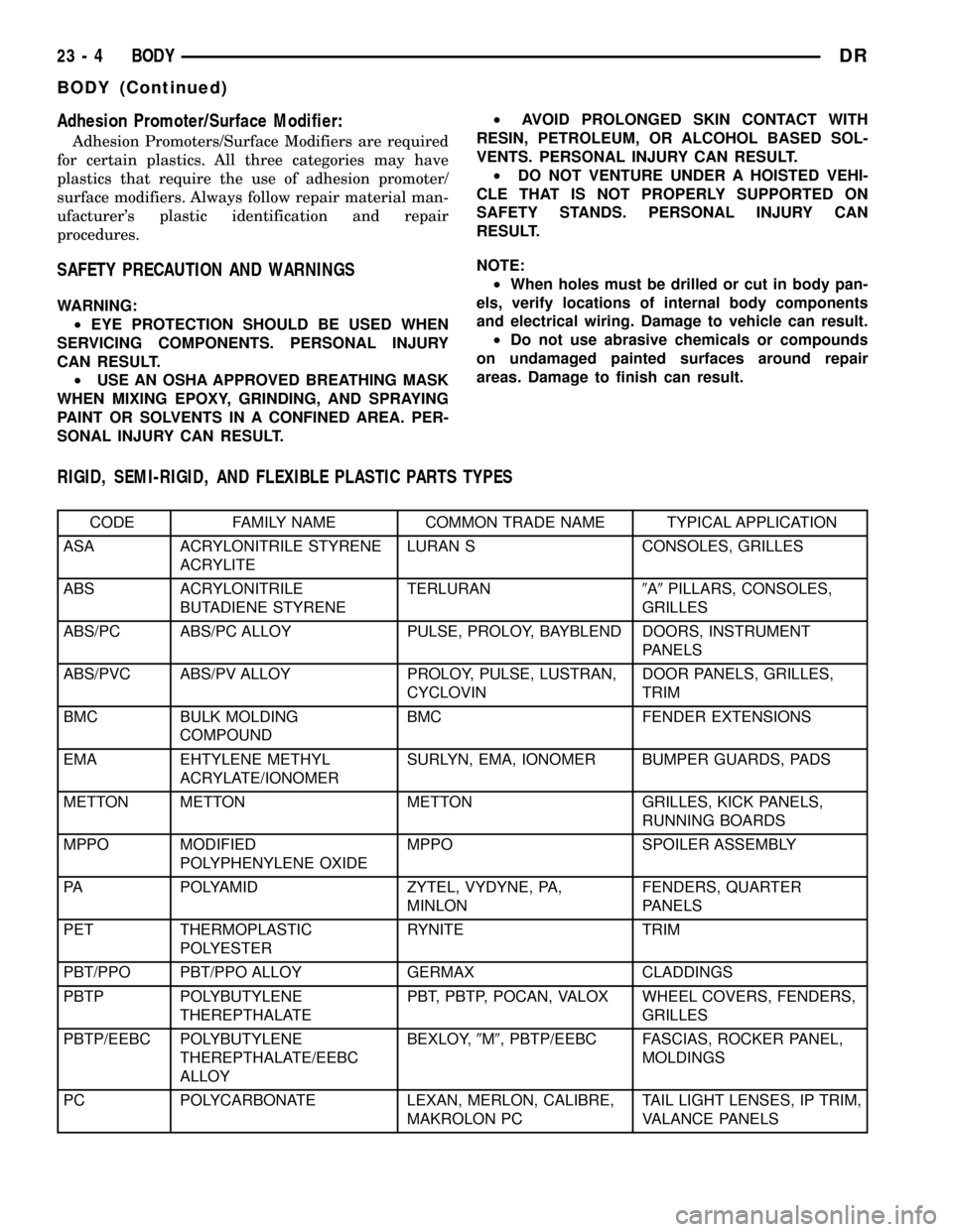
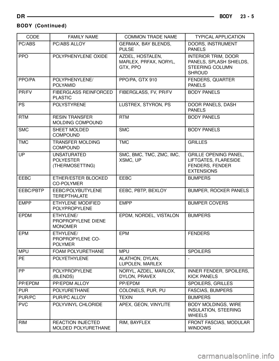
RIGID, SEMI-RIGID, AND FLEXIBLE PLASTIC PARTS TYPES
CODE FAMILY NAME COMMON TRADE NAME TYPICAL APPLICATION
ASA ACRYLONITRILE STYRENE
ACRYLITELURAN S CONSOLES, GRILLES
ABS ACRYLONITRILE
BUTADIENE STYRENETERLURAN9A9PILLARS, CONSOLES,
GRILLES
ABS/PC ABS/PC ALLOY PULSE, PROLOY, BAYBLEND DOORS, INSTRUMENT
PANELS
ABS/PVC ABS/PV ALLOY PROLOY, PULSE, LUSTRAN,
CYCLOVINDOOR PANELS, GRILLES,
TRIM
BMC BULK MOLDING
COMPOUNDBMC FENDER EXTENSIONS
EMA EHTYLENE METHYL
ACRYLATE/IONOMERSURLYN, EMA, IONOMER BUMPER GUARDS, PADS
METTON METTON METTON GRILLES, KICK PANELS,
RUNNING BOARDS
MPPO MODIFIED
POLYPHENYLENE OXIDEMPPO SPOILER ASSEMBLY
PA POLYAMID ZYTEL, VYDYNE, PA,
MINLONFENDERS, QUARTER
PANELS
PET THERMOPLASTIC
POLYESTERRYNITE TRIM
PBT/PPO PBT/PPO ALLOY GERMAX CLADDINGS
PBTP POLYBUTYLENE
THEREPTHALATEPBT, PBTP, POCAN, VALOX WHEEL COVERS, FENDERS,
GRILLES
PBTP/EEBC POLYBUTYLENE
THEREPTHALATE/EEBC
ALLOYBEXLOY,9M9, PBTP/EEBC FASCIAS, ROCKER PANEL,
MOLDINGS
PC POLYCARBONATE LEXAN, MERLON, CALIBRE,
MAKROLON PCTAIL LIGHT LENSES, IP TRIM,
VALANCE PANELS
23 - 4 BODYDR
BODY (Continued)
Page 2300 of 2627
CODE FAMILY NAME COMMON TRADE NAME TYPICAL APPLICATION
PC/ABS PC/ABS ALLOY GERMAX, BAY BLENDS,
PULSEDOORS, INSTRUMENT
PANELS
PPO POLYPHENYLENE OXIDE AZDEL, HOSTALEN,
MARLEX, PRFAX, NORYL,
GTX, PPOINTERIOR TRIM, DOOR
PANELS, SPLASH SHIELDS,
STEERING COLUMN
SHROUD
PPO/PA POLYPHENYLENE/
POLYAMIDPPO/PA, GTX 910 FENDERS, QUARTER
PANELS
PR/FV FIBERGLASS REINFORCED
PLASTICFIBERGLASS, FV, PR/FV BODY PANELS
PS POLYSTYRENE LUSTREX, STYRON, PS DOOR PANELS, DASH
PANELS
RTM RESIN TRANSFER
MOLDING COMPOUNDRTM BODY PANELS
SMC SHEET MOLDED
COMPOUNDSMC BODY PANELS
TMC TRANSFER MOLDING
COMPOUNDTMC GRILLES
UP UNSATURATED
POLYESTER
(THERMOSETTING)SMC, BMC, TMC, ZMC, IMC,
XSMC, UPGRILLE OPENING PANEL,
LIFTGATES, FLARESIDE
FENDERS, FENDER
EXTENSIONS
EEBC ETHER/ESTER BLOCKED
CO-POLYMEREEBC BUMPERS
EEBC/PBTP EEBC/POLYBUTYLENE
TEREPTHALATEEEBC, PBTP, BEXLOY BUMPER, ROCKER PANELS
EMPP ETHYLENE MODIFIED
POLYPROPYLENEEMPP BUMPER COVERS
EPDM ETHYLENE/
PROPROPYLENE DIENE
MONOMEREPDM, NORDEL, VISTALON BUMPERS
EPM ETHYLENE/
PROPROPYLENE CO-
POLYMEREPM FENDERS
MPU FOAM POLYURETHANE MPU SPOILERS
PE POLYETHYLENE ALATHON, DYLAN,
LUPOLEN, MARLEX-
PP POLYPROPYLENE
(BLENDS)NORYL, AZDEL, MARLOX,
DYLON, PRAVEXINNER FENDER, SPOILERS,
KICK PANELS
PP/EPDM PP/EPDM ALLOY PP/EPDM SPOILERS, GRILLES
PUR POLYURETHANE COLONELS, PUR, PU FASCIAS, BUMPERS
PUR/PC PUR/PC ALLOY TEXIN BUMPERS
PVC POLYVINYL CHLORIDE APEX, GEON, VINYLITE BODY MOLDINGS, WIRE
INSULATION, STEERING
WHEELS
RIM REACTION INJECTED
MOLDED POLYURETHANERIM, BAYFLEX FRONT FASCIAS, MODULAR
WINDOWS
DRBODY 23 - 5
BODY (Continued)
Page 2303 of 2627
should be stripped of paint and freed from wax and
oil. Scuff surfaces around repair area with 360 grit
wet/dry sandpaper, or equivalent, to assure adhesion
of repair materials.
PATCHING PANELS
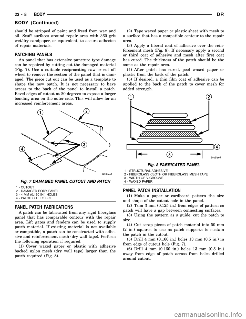
An panel that has extensive puncture type damage
can be repaired by cutting out the damaged material
(Fig. 7). Use a suitable reciprocating saw or cut off
wheel to remove the section of the panel that is dam-
aged. The piece cut out can be used as a template to
shape the new patch. It is not necessary to have
access to the back of the panel to install a patch.
Bevel edges of cutout at 20 degrees to expose a larger
bonding area on the outer side. This will allow for an
increased reinforcement areas.
PANEL PATCH FABRICATIONS
A patch can be fabricated from any rigid fiberglass
panel that has comparable contour with the repair
area. Lift gates and fenders can be used to supply
patch material. If existing material is not available
or compatible, a patch can be constructed with adhe-
sive and reinforcement mesh (dry wall tape). Perform
the following operation if required:
(1) Cover waxed paper or plastic with adhesive
backed nylon mesh (dry wall tape) larger than the
patch required (Fig. 8).(2) Tape waxed paper or plastic sheet with mesh to
a surface that has a compatible contour to the repair
area.
(3) Apply a liberal coat of adhesive over the rein-
forcement mesh (Fig. 8). If necessary apply a second
or third coat of adhesive and mesh after first coat
has cured. The thickness of the patch should be the
same as the repair area.
(4) After patch has cured, peel waxed paper or
plastic from the back of the patch.
(5) If desired, a thin film coat of adhesive can be
applied to the back of the patch to cover mesh for
added strength.
PANEL PATCH INSTALLATION
(1) Make a paper or cardboard pattern the size
and shape of the cutout hole in the panel.
(2) Trim 3 mm (0.125 in.) from edges of pattern so
patch will have a gap between connecting surfaces.
(3) Using the pattern as a guide, cut the patch to
size.
(4) Cut scrap pieces of patch material into 50 mm
(2 in.) squares to use as patch supports to sustain
the patch in the cutout.
(5) Drill 4 mm (0.160 in.) holes 13 mm (0.5 in.) in
from edge of cutout hole (Fig. 7).
(6) Drill 4 mm (0.160 in.) holes 13 mm (0.5 in.)
away from edge of patch across from holes drilled
around cutout.
Fig. 7 DAMAGED PANEL CUTOUT AND PATCH
1 - CUTOUT
2 - DAMAGED BODY PANEL
3-4MM(0.160 IN.) HOLES
4 - PATCH CUT TO SIZE
Fig. 8 FABRICATED PANEL
1 - STRUCTURAL ADHESIVE
2 - FIBERGLASS CLOTH OR FIBERGLASS MESH TAPE
3 - WIDTH OF V-GROOVE
4 - WAXED PAPER
23 - 8 BODYDR
BODY (Continued)
Page 2306 of 2627
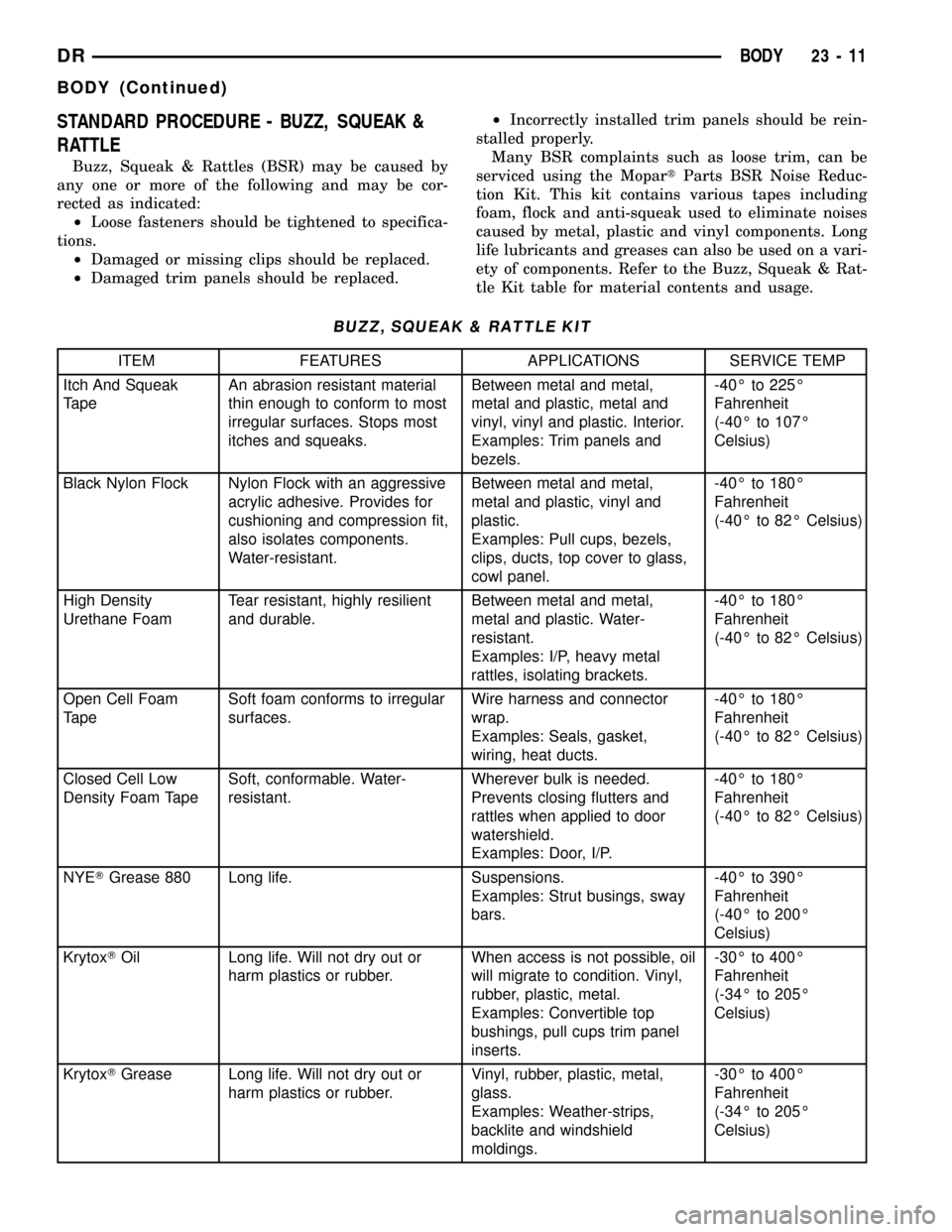
STANDARD PROCEDURE - BUZZ, SQUEAK &
RATTLE
Buzz, Squeak & Rattles (BSR) may be caused by
any one or more of the following and may be cor-
rected as indicated:
²Loose fasteners should be tightened to specifica-
tions.
²Damaged or missing clips should be replaced.
²Damaged trim panels should be replaced.²Incorrectly installed trim panels should be rein-
stalled properly.
Many BSR complaints such as loose trim, can be
serviced using the MopartParts BSR Noise Reduc-
tion Kit. This kit contains various tapes including
foam, flock and anti-squeak used to eliminate noises
caused by metal, plastic and vinyl components. Long
life lubricants and greases can also be used on a vari-
ety of components. Refer to the Buzz, Squeak & Rat-
tle Kit table for material contents and usage.
BUZZ, SQUEAK & RATTLE KIT
ITEM FEATURES APPLICATIONS SERVICE TEMP
Itch And Squeak
TapeAn abrasion resistant material
thin enough to conform to most
irregular surfaces. Stops most
itches and squeaks.Between metal and metal,
metal and plastic, metal and
vinyl, vinyl and plastic. Interior.
Examples: Trim panels and
bezels.-40É to 225É
Fahrenheit
(-40É to 107É
Celsius)
Black Nylon Flock Nylon Flock with an aggressive
acrylic adhesive. Provides for
cushioning and compression fit,
also isolates components.
Water-resistant.Between metal and metal,
metal and plastic, vinyl and
plastic.
Examples: Pull cups, bezels,
clips, ducts, top cover to glass,
cowl panel.-40É to 180É
Fahrenheit
(-40É to 82É Celsius)
High Density
Urethane FoamTear resistant, highly resilient
and durable.Between metal and metal,
metal and plastic. Water-
resistant.
Examples: I/P, heavy metal
rattles, isolating brackets.-40É to 180É
Fahrenheit
(-40É to 82É Celsius)
Open Cell Foam
TapeSoft foam conforms to irregular
surfaces.Wire harness and connector
wrap.
Examples: Seals, gasket,
wiring, heat ducts.-40É to 180É
Fahrenheit
(-40É to 82É Celsius)
Closed Cell Low
Density Foam TapeSoft, conformable. Water-
resistant.Wherever bulk is needed.
Prevents closing flutters and
rattles when applied to door
watershield.
Examples: Door, I/P.-40É to 180É
Fahrenheit
(-40É to 82É Celsius)
NYETGrease 880 Long life. Suspensions.
Examples: Strut busings, sway
bars.-40É to 390É
Fahrenheit
(-40É to 200É
Celsius)
KrytoxTOil Long life. Will not dry out or
harm plastics or rubber.When access is not possible, oil
will migrate to condition. Vinyl,
rubber, plastic, metal.
Examples: Convertible top
bushings, pull cups trim panel
inserts.-30É to 400É
Fahrenheit
(-34É to 205É
Celsius)
KrytoxTGrease Long life. Will not dry out or
harm plastics or rubber.Vinyl, rubber, plastic, metal,
glass.
Examples: Weather-strips,
backlite and windshield
moldings.-30É to 400É
Fahrenheit
(-34É to 205É
Celsius)
DRBODY 23 - 11
BODY (Continued)
Page 2369 of 2627

CAUTION: Do not use abrasive chemicals or com-
pounds on painted surfaces. Damage to finish can
result.
Do not use harsh alkaline based cleaning solvents
on painted surfaces. Damage to finish or color can
result.
PAINT TOUCH-UP
DESCRIPTION
When a painted metal surface has been scratched
or chipped, it should be touched-up as soon as possi-
ble to avoid corrosion. For best results, use MOPARt
Scratch Filler/Primer, Touch-Up Paints and Clear Top
Coat. (Refer to VEHICLE DATA/VEHICLE INFOR-
MATION/BODY CODE PLATE - DESCRIPTION) for
Body Code Plate information.
WARNING: USE AN OSHA APPROVED RESPIRATOR
AND SAFETY GLASSES WHEN SPRAYING PAINT
OR SOLVENTS IN A CONFINED AREA. PERSONAL
INJURY CAN RESULT.
STANDARD PROCEDURE - PAINT TOUCH-UP
(1) Scrape loose paint and corrosion from inside
scratch or chip.
(2) Clean affected area with MOPARtTar/Road
Oil Remover or equivalent, and allow to dry.
(3) Fill the inside of the scratch or chip with a coat
of filler/primer. Do not overlap primer onto good sur-
face finish. The applicator brush should be wet
enough to puddle-fill the scratch or chip without run-
ning. Do not stroke brush applicator on body surface.
Allow the filler/primer to dry hard.
(4) Cover the filler/primer with color touch-up
paint. Do not overlap touch-up color onto the original
color coat around the scratch or chip. Butt the new
color to the original color, if possible. Do not stroke
applicator brush on body surface. Allow touch-up
paint to dry hard.(5) On vehicles without clearcoat, the touch-up
color can be lightly finesse sanded (1500 grit) and
polished with rubbing compound.
(6) On vehicles with clearcoat, apply clear top coat
to touch-up paint with the same technique as
described in Step 4. Allow clear top coat to dry hard.
If desired, Step 5 can be performed on clear top coat.
WARNING: AVOID PROLONGED SKIN CONTACT
WITH PETROLEUM OR ALCOHOL ± BASED CLEAN-
ING SOLVENTS. PERSONAL INJURY CAN
RESULT.AVOID PROLONGED SKIN CONTACT WITH
PETROLEUM OR ALCOHOL ± BASED CLEANING
SOLVENTS. PERSONAL INJURY CAN RESULT.
FINESSE SANDING/BUFFING &
POLISHING
DESCRIPTION
CAUTION: Do not remove more than .5 mils of
clearcoat finish, if equipped. Basecoat paint must
retain clearcoat for durability.
Use a Paint Thickness Gauge #PR-ETG-2X or equiv-
alent to determine film thickness before and after
the repair.
Minor acid etching, orange peel, or smudging in
clearcoat or single-stage finishes can be reduced with
light finesse sanding, hand buffing, and polishing.If
the finish has been finesse sanded in the past,
it cannot be repeated. Finesse sanding opera-
tion should be performed by a trained automo-
tive paint technician.
23 - 74 PAINTDR
BASECOAT/CLEARCOAT FINISH (Continued)