Page 2059 of 2627
HYDRAULIC FLOW IN MANUAL SECOND
21 - 356 AUTOMATIC TRANSMISSION - 45RFE/545RFEDR
AUTOMATIC TRANSMISSION - 45RFE/545RFE (Continued)
Page 2060 of 2627
HYDRAULIC FLOW IN MANUAL SECOND (FAILSAFE)
DRAUTOMATIC TRANSMISSION - 45RFE/545RFE 21 - 357
AUTOMATIC TRANSMISSION - 45RFE/545RFE (Continued)
Page 2061 of 2627

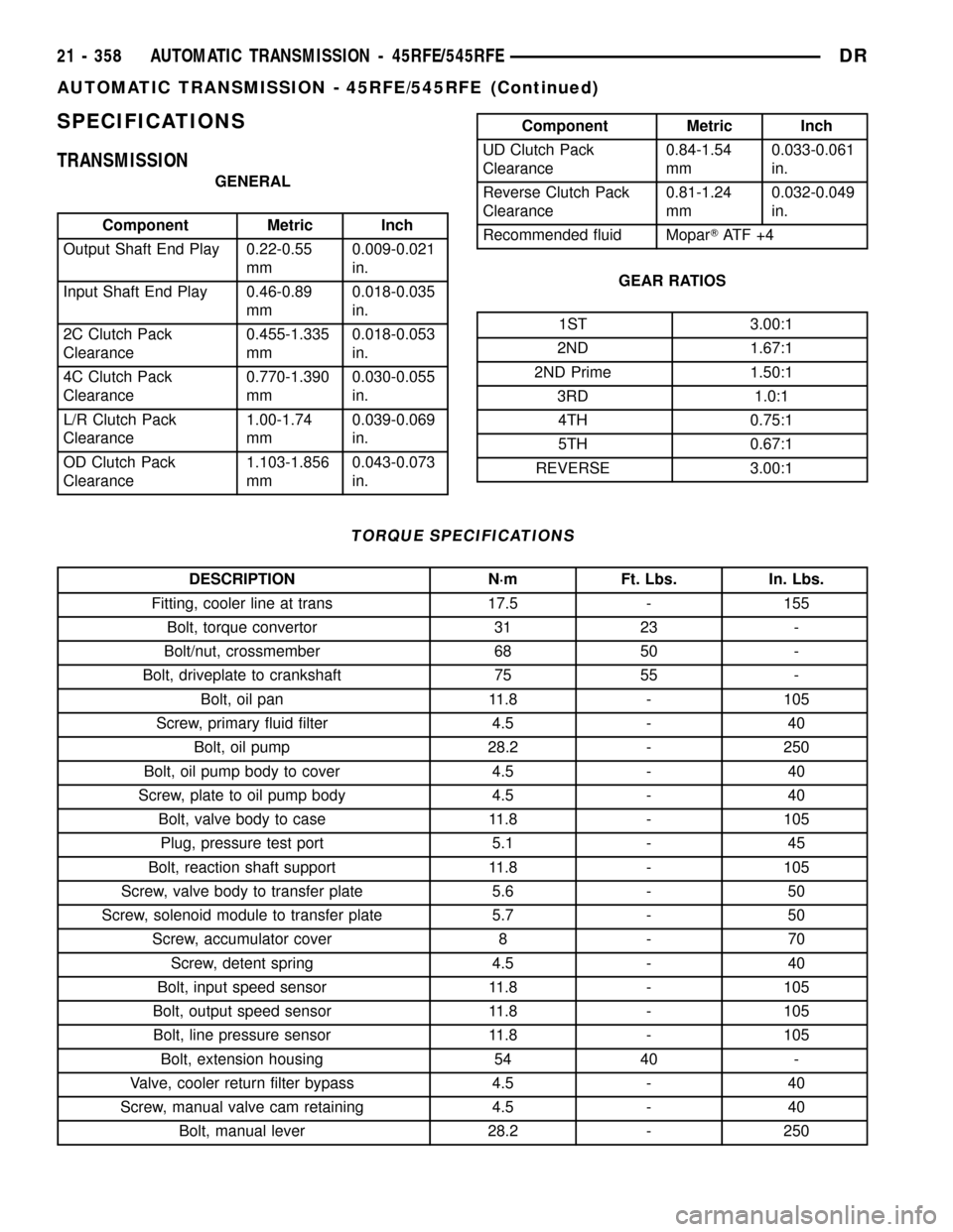
SPECIFICATIONS
TRANSMISSION
GENERAL
Component Metric Inch
Output Shaft End Play 0.22-0.55
mm0.009-0.021
in.
Input Shaft End Play 0.46-0.89
mm0.018-0.035
in.
2C Clutch Pack
Clearance0.455-1.335
mm0.018-0.053
in.
4C Clutch Pack
Clearance0.770-1.390
mm0.030-0.055
in.
L/R Clutch Pack
Clearance1.00-1.74
mm0.039-0.069
in.
OD Clutch Pack
Clearance1.103-1.856
mm0.043-0.073
in.
Component Metric Inch
UD Clutch Pack
Clearance0.84-1.54
mm0.033-0.061
in.
Reverse Clutch Pack
Clearance0.81-1.24
mm0.032-0.049
in.
Recommended fluid MoparTAT F + 4
GEAR RATIOS
1ST 3.00:1
2ND 1.67:1
2ND Prime 1.50:1
3RD 1.0:1
4TH 0.75:1
5TH 0.67:1
REVERSE 3.00:1
TORQUE SPECIFICATIONS
DESCRIPTION N´m Ft. Lbs. In. Lbs.
Fitting, cooler line at trans 17.5 - 155
Bolt, torque convertor 31 23 -
Bolt/nut, crossmember 68 50 -
Bolt, driveplate to crankshaft 75 55 -
Bolt, oil pan 11.8 - 105
Screw, primary fluid filter 4.5 - 40
Bolt, oil pump 28.2 - 250
Bolt, oil pump body to cover 4.5 - 40
Screw, plate to oil pump body 4.5 - 40
Bolt, valve body to case 11.8 - 105
Plug, pressure test port 5.1 - 45
Bolt, reaction shaft support 11.8 - 105
Screw, valve body to transfer plate 5.6 - 50
Screw, solenoid module to transfer plate 5.7 - 50
Screw, accumulator cover 8 - 70
Screw, detent spring 4.5 - 40
Bolt, input speed sensor 11.8 - 105
Bolt, output speed sensor 11.8 - 105
Bolt, line pressure sensor 11.8 - 105
Bolt, extension housing 54 40 -
Valve, cooler return filter bypass 4.5 - 40
Screw, manual valve cam retaining 4.5 - 40
Bolt, manual lever 28.2 - 250
21 - 358 AUTOMATIC TRANSMISSION - 45RFE/545RFEDR
AUTOMATIC TRANSMISSION - 45RFE/545RFE (Continued)
Page 2062 of 2627
SPECIAL TOOLS
RFE TRANSMISSION
Gauge, Oil Pressure - C-3292
Gauge, Oil Pressure - C-3293SP
Dial Indicator - C-3339
Installer, Seal - C-3860-A
Compressor, Spring - 8249
Compressor, Spring - 8250
Compressor, Spring - 8251
Installer, Piston - 8252
DRAUTOMATIC TRANSMISSION - 45RFE/545RFE 21 - 359
AUTOMATIC TRANSMISSION - 45RFE/545RFE (Continued)
Page 2063 of 2627
Installer, Seal - 8253
Installer, Seal - 8254
Installer, Snap-ring - 8255
Stand, Support - 8257
Adapter, Pressure Tap - 8258-A
Adapter, Line Pressure - 8259
Fixture, Input Clutch Pressure - 8260
Plate, Alignment - 8261
21 - 360 AUTOMATIC TRANSMISSION - 45RFE/545RFEDR
AUTOMATIC TRANSMISSION - 45RFE/545RFE (Continued)
Page 2064 of 2627
End Play Set - 8266
Compressor, Spring - 8285
Installer, Bearing - 8320
Wrench, Filter - 8321
Installer, Piston - 8504
DRAUTOMATIC TRANSMISSION - 45RFE/545RFE 21 - 361
AUTOMATIC TRANSMISSION - 45RFE/545RFE (Continued)
Page 2065 of 2627

4C RETAINER/BULKHEAD
DISASSEMBLY
(1) Remove the 2C piston belleville spring snap-
ring from the 4C retainer /bulkhead (Fig. 60).
(2) Remove the 2C piston Belleville spring from
the retainer/bulkhead (Fig. 60).
(3) Remove the 2C piston from the retainer/bulk-
head. Use 20 psi of air pressure to remove the piston
if necessary.
(4) Remove the 4C clutch snap-ring from the
retainer/bulkhead (Fig. 60).(5) Remove the 4C clutch pack from the retainer/
bulkhead (Fig. 60).
(6) Using Spring Compressor 8250 and a suitable
shop press, compress the 4C piston return spring and
remove the snap-ring (Fig. 60).
(7) Remove the 4C piston return spring and piston
from the retainer/bulkhead (Fig. 60). Use 20 psi of
air pressure to remove the piston if necessary.
Fig. 60 4C Retainer/Bulkhead Components
1 - SEAL 8 - REACTION PLATE
2 - 2C PISTON 9 - SNAP-RING
3 - PLATE 10 - RETURN SPRING
4 - DISC 11 - SEAL
5 - 2C BELLEVILLE SPRING 12 - 4C PISTON
6 - SNAP-RING 13 - 4C RETAINER/BULKHEAD
7 - SNAP-RING (SELECT)
21 - 362 AUTOMATIC TRANSMISSION - 45RFE/545RFEDR
Page 2066 of 2627

ASSEMBLY
(1) Clean and inspect all components. Replace any
components which show evidence of excessive wear
or scoring.
(2) Install new seals on the 2C and 4C pistons
(Fig. 60).
(3) Lubricate all seals with MopartATF +4 prior
to installation.
(4) Install the 4C piston into the 4C retainer/bulk-
head (Fig. 60).
(5) Position the 4C piston return spring onto the
4C piston.
(6) Using Spring Compressor 8250 and a suitable
shop press, compress the 4C piston return spring and
install the snap-ring (Fig. 61).
(7) Assemble and install the 4C clutch pack into
the retainer/bulkhead (Fig. 60) with the steel separa-
tor plate against the piston.(8) Install the 4C reaction plate and snap-ring into
the retainer/bulkhead (Fig. 60). The 4C reaction plate
is non-directional.
(9) Measure the 4C clutch clearance. The correct
clutch clearance is 0.77-1.39 mm (0.030-0.055 in.).
The snap-ring is selectable. Install the chosen snap-
ring and re-measure to verify the selection.
(10) Install the 2C piston into the retainer/bulk-
head (Fig. 60).
(11) Position the 2C Belleville spring onto the 2C
piston.
(12) Position the 2C Belleville spring snap-ring
onto the 2C Belleville spring (Fig. 60).
(13) Using Spring Compressor 8249 and a suitable
shop press (Fig. 62), compress the belleville spring
until the snap-ring is engaged with the snap-ring
groove in the retainer/bulkhead.
Fig. 61 Compress 4C Piston Return Spring Using
Tool 8250
1 - PRESS
2 - TOOL 8250Fig. 62 Compress 2C Belleville Spring Using Tool
8249
1 - PRESS
2 - TOOL 8249
DRAUTOMATIC TRANSMISSION - 45RFE/545RFE 21 - 363
4C RETAINER/BULKHEAD (Continued)