1998 DODGE RAM 1500 transmission oil
[x] Cancel search: transmission oilPage 832 of 2627

8W-30 FUEL/IGNITION SYSTEM
Component Page
A/C Compressor Clutch Relay............ 8W-30-9, 58
A/C Pressure Transducer......... 8W-30-23, 28, 29, 45
Accelerator Pedal Position Sensor . . . 8W-30-29, 47, 64, 65
Adjustable Pedal Motor................. 8W-30-61
Adjustable Pedal Relay.................. 8W-30-61
Adjustable Pedal Switch................. 8W-30-61
Ambient Temperature Sensor............. 8W-30-30
Auto Shut Down Relay................... 8W-30-4
Battery............................ 8W-30-52
Battery Temperature Sensor............ 8W-30-12, 56
Brake Lamp Switch............. 8W-30-8, 36, 57, 63
Camshaft Position Sensor........ 8W-30-10, 29, 45, 46
Capacitor........................... 8W-30-13
Clockspring..................... 8W-30-8, 36, 59
Coil On Plug No. 1.................. 8W-30-14, 39
Coil On Plug No. 2.................. 8W-30-15, 37
Coil On Plug No. 3.................. 8W-30-14, 39
Coil On Plug No. 4.................. 8W-30-15, 37
Coil On Plug No. 5.................. 8W-30-16, 39
Coil On Plug No. 6.................. 8W-30-13, 37
Coil On Plug No. 7.................. 8W-30-16, 39
Coil On Plug No. 8.................. 8W-30-13, 37
Condenser Fan Relay.................... 8W-30-9
Controller Antilock Brake............ 8W-30-6, 11, 57
Crankshaft Position Sensor............ 8W-30-10, 46
Data Link Connector............... 8W-30-9, 22, 55
Data Link Connector-Engine.............. 8W-30-51
EGR Solenoid................... 8W-30-28, 29, 32
Electronic Throttle Control Module.......... 8W-30-35
Engine Control Module....... 8W-30-42, 43, 44, 45, 46,
47, 48, 49, 50, 51, 52, 53, 54,
55, 56, 57, 58, 59, 60, 62, 63, 64, 65
Engine Coolant Temperature Sensor.... 8W-30-23, 41, 47
Engine Oil Pressure Switch.......... 8W-30-2, 53, 56
EVAP/Purge Solenoid................... 8W-30-12
Front Control Module................... 8W-30-61
Fuel Control Actuator................... 8W-30-50
Fuel Heater......................... 8W-30-60
Fuel Heater Relay..................... 8W-30-60
Fuel Injector No. 1.................. 8W-30-14, 40
Fuel Injector No. 2.................. 8W-30-15, 38
Fuel Injector No. 3.................. 8W-30-14, 40
Fuel Injector No. 4.................. 8W-30-15, 38
Fuel Injector No. 5.................. 8W-30-14, 40
Fuel Injector No. 6.................. 8W-30-15, 38
Fuel Injector No. 7.................. 8W-30-16, 40
Fuel Injector No. 8.................. 8W-30-13, 38
Fuel Injector Pack No. 1................. 8W-30-42
Fuel Injector Pack No. 2............ 8W-30-42, 43, 44
Fuel Injector Pack No. 3................. 8W-30-44
Fuel Pump Module................... 8W-30-3, 58
Fuel Pump Motor...................... 8W-30-48
Fuel Pump Relay....................... 8W-30-3
Fuse 2.............................. 8W-30-4
Fuse 5........................... 8W-30-25, 62
Fuse 12............................ 8W-30-60
Fuse 17............................. 8W-30-3
Fuse 19............................ 8W-30-52
Fuse 23............................. 8W-30-2Component Page
Fuse 36.......................... 8W-30-54, 61
Fuse 40............................ 8W-30-61
Fuse 49............................. 8W-30-4
Fuse 50..................... 8W-30-2, 55, 58, 62
Fusible Link......................... 8W-30-52
G104........................ 8W-30-3, 8, 25, 60
G105............................ 8W-30-56, 58
G107........... 8W-30-2, 7, 15, 18, 19, 20, 21, 30, 32
G114 .............................. 8W-30-53
G120............................ 8W-30-51, 60
G201............................... 8W-30-6
G202.............................. 8W-30-61
Generator......................... 8W-30-7, 51
Idle Air Control Motor................... 8W-30-9
Ignition Switch..................... 8W-30-6, 22
Inlet Air Temperature Sensor............. 8W-30-49
Input Speed Sensor.................... 8W-30-24
Instrument Cluster.................... 8W-30-30
Intake Air Heater Relay No. 1............. 8W-30-56
Intake Air Heater Relay No. 2............. 8W-30-56
Intake Air Temperature Sensor.......... 8W-30-23, 41
Intake Air Temperature/Manifold Absolute
Pressure Sensor..................... 8W-30-50
Integrated Power Module.... 8W-30-2, 3, 4, 9, 25, 52, 54,
55, 58, 60, 61, 62, 64
Knock Sensor........................ 8W-30-31
Knock Sensor-Left..................... 8W-30-33
Knock Sensor-Right.................... 8W-30-33
Lift Pump Motor...................... 8W-30-51
Line Pressure Sensor................... 8W-30-17
Manifold Absolute Pressure Sensor..... 8W-30-23, 29, 41
Natural Vacuum Leak Detection Assembly..... 8W-30-7
Output Speed Sensor................. 8W-30-24, 62
Oxygen Sensor 1/1 Upstream........... 8W-30-20, 21
Oxygen Sensor 1/2 Downstream......... 8W-30-18, 19
Oxygen Sensor 2/1 Upstream........... 8W-30-20, 21
Oxygen Sensor 2/2 Downstream......... 8W-30-18, 19
Oxygen Sensor Downstream Relay........... 8W-30-4
Power Steering Pressure Switch............ 8W-30-7
Powertrain Control Module....... 8W-30-2, 3, 4, 5, 6, 7,
8, 9, 10, 11, 12, 13, 14, 15, 16,
17, 18, 19, 20, 21, 22, 23, 24,
25, 26, 27, 28, 29, 30, 31, 32,
33, 35, 36, 37, 38, 39, 40, 41
PTCNo.1 ....................... 8W-30-3, 9, 58
Pto Switch........................... 8W-30-6
Speed Control Servo.................. 8W-30-8, 63
Speed Control Switch-Left............. 8W-30-36, 59
Speed Control Switch-Right............ 8W-30-36, 59
Starter Motor Relay.................. 8W-30-2, 64
Throttle Position Sensor................. 8W-30-17
Tow/Haul Overdrive Switch............. 8W-30-6, 64
Transmission Control Relay............ 8W-30-25, 62
Transmission Range Sensor............... 8W-30-64
Transmission Solenoid Assembly......... 8W-30-54, 62
Transmission Solenoid/TRS Assembly . 8W-30-5, 25, 26, 27
Vacuum Pump........................ 8W-30-58
Vistronic Fan Drive.................... 8W-30-54
Water In Fuel Sensor................ 8W-30-47, 48
DR8W-30 FUEL/IGNITION SYSTEM 8W - 30 - 1
Page 1109 of 2627

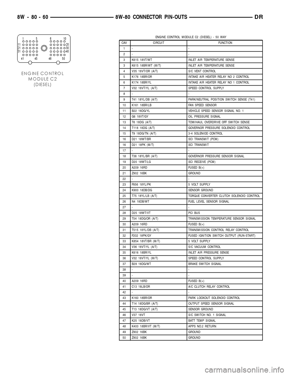
ENGINE CONTROL MODULE C2 (DIESEL) - 50 WAY
CAV CIRCUIT FUNCTION
1- -
2- -
3 K615 18VT/WT INLET AIR TEMPERATURE SENSE
3 K615 18BR/WT (M/T) INLET AIR TEMPERATURE SENSE
4 V35 18VT/OR (A/T) S/C VENT CONTROL
5 K176 18BR/OR INTAKE AIR HEATER RELAY NO 2 CONTROL
6 K174 18BR/YL INTAKE AIR HEATER RELAY NO 1 CONTROL
7 V32 18VT/YL (A/T) SPEED CONTROL SUPPLY
8- -
9 T41 18YL/DB (A/T) PARK/NEUTRAL POSITION SWITCH SENSE (T41)
10 K161 18BR/LB FAN SPEED SENSOR
11 B22 18DG/YL VEHICLE SPEED SENSOR SIGNAL NO. 1
12 G6 18VT/GY OIL PRESSURE SIGNAL
13 T6 18DG (A/T) TOW/HAUL OVERDRIVE OFF SWITCH SENSE
14 T118 18DG (A/T) GOVERNOR PRESSURE SOLENOID CONTROL
15 T9 18DG/TN (A/T) 3-4 SOLENIOD CONTROL
16 D21 18WT/BR SCI TRANSMIT (PCM)
16 D21 18PK (M/T) SCI TRANSMIT
17 - -
18 T38 18YL/BR (A/T) GOVERNOR PRESSURE SENSOR SIGNAL
19 D20 18WT/LG SCI RECEIVE (PCM)
20 A209 16RD FUSED B(+)
21 Z902 16BK GROUND
22 - -
23 F856 18YL/PK 5 VOLT SUPPLY
24 K900 18DB/DG SENSOR GROUND
25 T75 18YL/LB (A/T) TORQUE CONVERTER CLUTCH SOLENOID CONTROL
26 N4 18DB/WT FUEL LEVEL SENSOR SIGNAL
27 - -
28 D25 18WT/VT PCI BUS
29 T54 18DG/OR (A/T) TRANSMISSION TEMPERATURE SENSOR SIGNAL
30 A209 16RD FUSED B(+)
31 T515 18YL/DB (A/T) TRANSMISSION CONTROL RELAY CONTROL
32 F202 18PK/GY FUSED IGNITION SWITCH OUTPUT (RUN-START)
33 K854 18VT/BR (M/T) 5 VOLT SUPPLY
34 V36 18VT/YL (A/T) S/C VACUUM CONTROL
35 K616 18BR/YL INLET AIR PRESSURE SENSE
36 V32 18VT/YL (M/T) SPEED CONTROL SUPPLY
37 B29 18DG/WT BRAKE SWITCH SIGNAL
38 - -
39 - -
40 A209 16RD FUSED B(+)
41 C13 18LB/OR A/C CLUTCH RELAY CONTROL
42 - -
43 K160 18BR/OR PARK LOCKOUT SOLENOID CONTROL
44 T14 18DG/BR (A/T) OUTPUT SPEED SENSOR SIGNAL
45 T13 18DG/VT (A/T) SENSOR GROUND
46 V37 18VT S/C SWITCH NO. 1 SIGNAL
47 K25 18DB/VT BATT TEMP SIGNAL
48 K400 18BR/VT (M/T) APPS NO.2 RETURN
49 Z902 16BK GROUND
50 Z902 16BK GROUND
8W - 80 - 60 8W-80 CONNECTOR PIN-OUTSDR
Page 1158 of 2627

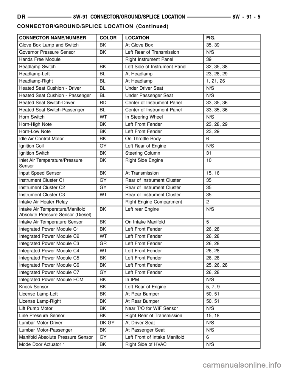
CONNECTOR NAME/NUMBER COLOR LOCATION FIG.
Glove Box Lamp and Switch BK At Glove Box 35, 39
Governor Pressure Sensor BK Left Rear of Transmission N/S
Hands Free Module Right Instrument Panel 39
Headlamp Switch BK Left Side of Instrument Panel 32, 35, 38
Headlamp-Left BL At Headlamp 23, 28, 29
Headlamp-Right BL At Headlamp 1, 21, 26
Heated Seat Cushion - Driver BL Under Driver Seat N/S
Heated Seat Cushion - Passenger BL Under Passenger Seat N/S
Heated Seat Switch-Driver RD Center of Instrument Panel 33, 35, 36
Heated Seat Switch-Passenger BL Center of Instrument Panel 33, 35, 36
Horn Switch WT In Steering Wheel N/S
Horn-High Note BK Left Front Fender 23, 28, 29
Horn-Low Note BK Left Front Fender 23, 29
Idle Air Control Motor BK On Throttle Body 6
Ignition Coil GY Left Rear of Engine N/S
Ignition Switch BK Steering Column 31
Inlet Air Temperature/Pressure
SensorBK Right Side Engine 10
Input Speed Sensor BK At Transmission 15, 16
Instrument Cluster C1 GY Rear of Instrument Cluster 35
Instrument Cluster C2 GY Rear of Instrument Cluster 35
Instrument Cluster C3 WT Rear of Instrument Cluster 35
Intake Air Heater Relay Right Engine Compartment 2
Intake Air Temperature/Manifold
Absolute Pressure Sensor (Diesel)BK Left rear Engine N/S
Intake Air Temperature Sensor BK On Intake Manifold 5
Integrated Power Module C1 BK Left Front Fender 26, 28
Integrated Power Module C2 WT Left Front Fender 26, 28
Integrated Power Module C3 GR Left Front Fender 26, 28
Integrated Power Module C4 WT Left Front Fender 26, 28
Integrated Power Module C5 BK Left Front Fender 26, 28
Integrated Power Module C6 BK Left Front Fender 25, 26, 28
Integrated Power Module C7 GY Left Front Fender 26, 28
Integrated Power Module FCM BK In IPM N/S
Knock Sensor BK Left Rear of Engine 5, 7, 9
License Lamp-Left BK At Rear Bumper 50, 51
License Lamp-Right BK At Rear Bumper 50, 51
Lift Pump Motor BK Near T/O for WIF Sensor N/S
Line Pressure Sensor BK Right Rear of Transmission 15, 18
Lumbar Motor-Driver DK GY At Driver Seat N/S
Lumbar Motor-Passenger BK At Passenger Seat N/S
Manifold Absolute Pressure Sensor GY Left Front of Intake Manifold 6
Mode Door Actuator 1 BK Right Side of HVAC N/S
DR8W-91 CONNECTOR/GROUND/SPLICE LOCATION 8W - 91 - 5
CONNECTOR/GROUND/SPLICE LOCATION (Continued)
Page 1232 of 2627

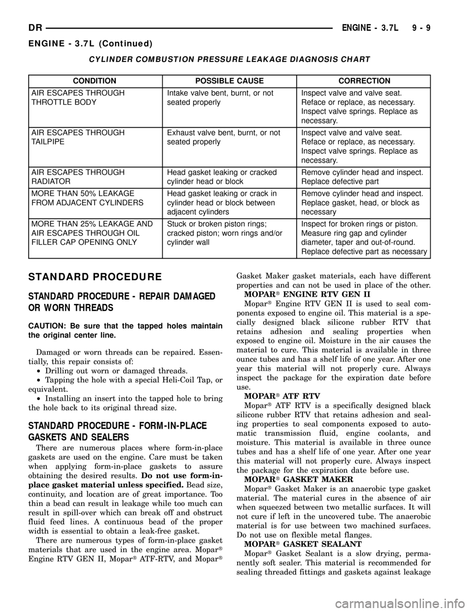
CYLINDER COMBUSTION PRESSURE LEAKAGE DIAGNOSIS CHART
CONDITION POSSIBLE CAUSE CORRECTION
AIR ESCAPES THROUGH
THROTTLE BODYIntake valve bent, burnt, or not
seated properlyInspect valve and valve seat.
Reface or replace, as necessary.
Inspect valve springs. Replace as
necessary.
AIR ESCAPES THROUGH
TAILPIPEExhaust valve bent, burnt, or not
seated properlyInspect valve and valve seat.
Reface or replace, as necessary.
Inspect valve springs. Replace as
necessary.
AIR ESCAPES THROUGH
RADIATORHead gasket leaking or cracked
cylinder head or blockRemove cylinder head and inspect.
Replace defective part
MORE THAN 50% LEAKAGE
FROM ADJACENT CYLINDERSHead gasket leaking or crack in
cylinder head or block between
adjacent cylindersRemove cylinder head and inspect.
Replace gasket, head, or block as
necessary
MORE THAN 25% LEAKAGE AND
AIR ESCAPES THROUGH OIL
FILLER CAP OPENING ONLYStuck or broken piston rings;
cracked piston; worn rings and/or
cylinder wallInspect for broken rings or piston.
Measure ring gap and cylinder
diameter, taper and out-of-round.
Replace defective part as necessary
STANDARD PROCEDURE
STANDARD PROCEDURE - REPAIR DAMAGED
OR WORN THREADS
CAUTION: Be sure that the tapped holes maintain
the original center line.
Damaged or worn threads can be repaired. Essen-
tially, this repair consists of:
²Drilling out worn or damaged threads.
²Tapping the hole with a special Heli-Coil Tap, or
equivalent.
²Installing an insert into the tapped hole to bring
the hole back to its original thread size.
STANDARD PROCEDURE - FORM-IN-PLACE
GASKETS AND SEALERS
There are numerous places where form-in-place
gaskets are used on the engine. Care must be taken
when applying form-in-place gaskets to assure
obtaining the desired results.Do not use form-in-
place gasket material unless specified.Bead size,
continuity, and location are of great importance. Too
thin a bead can result in leakage while too much can
result in spill-over which can break off and obstruct
fluid feed lines. A continuous bead of the proper
width is essential to obtain a leak-free gasket.
There are numerous types of form-in-place gasket
materials that are used in the engine area. Mopart
Engine RTV GEN II, MopartATF-RTV, and MopartGasket Maker gasket materials, each have different
properties and can not be used in place of the other.
MOPARtENGINE RTV GEN II
MopartEngine RTV GEN II is used to seal com-
ponents exposed to engine oil. This material is a spe-
cially designed black silicone rubber RTV that
retains adhesion and sealing properties when
exposed to engine oil. Moisture in the air causes the
material to cure. This material is available in three
ounce tubes and has a shelf life of one year. After one
year this material will not properly cure. Always
inspect the package for the expiration date before
use.
MOPARtATF RTV
MopartATF RTV is a specifically designed black
silicone rubber RTV that retains adhesion and seal-
ing properties to seal components exposed to auto-
matic transmission fluid, engine coolants, and
moisture. This material is available in three ounce
tubes and has a shelf life of one year. After one year
this material will not properly cure. Always inspect
the package for the expiration date before use.
MOPARtGASKET MAKER
MopartGasket Maker is an anaerobic type gasket
material. The material cures in the absence of air
when squeezed between two metallic surfaces. It will
not cure if left in the uncovered tube. The anaerobic
material is for use between two machined surfaces.
Do not use on flexible metal flanges.
MOPARtGASKET SEALANT
MopartGasket Sealant is a slow drying, perma-
nently soft sealer. This material is recommended for
sealing threaded fittings and gaskets against leakage
DRENGINE - 3.7L 9 - 9
ENGINE - 3.7L (Continued)
Page 1234 of 2627

(12) Disconnect heater hoses from heater core and
remove hose assembly.
(13) Disconnect throttle and speed control cables.
(14) Remove upper radiator hose from engine.
(15) Remove lower radiator hose from engine.
(16) Remove radiator/cooling module assembly.
(17) Disconnect the engine to body ground straps
at the left side of cowl.
(18) Disconnect the engine wiring harness at the
following points:
²Intake air temperature (IAT) sensor
²Fuel Injectors
²Throttle Position (TPS) Switch
²Idle Air Control (IAC) Motor
²Engine Oil Pressure Switch
²Engine Coolant Temperature (ECT) Sensor
²Manifold Absolute Pressure MAP) Sensor
²Camshaft Position (CMP) Sensor
²Coil Over Plugs
²Crankshaft Position Sensor
(19) Remove coil over plugs.
(20) Release fuel rail pressure.
(21) Remove fuel rail and secure away from
engine.
NOTE: It is not necessary to release the quick con-
nect fitting from the fuel supply line for engine
removal.
(22) Remove the PCV hose.
(23) Remove the breather hoses.
(24) Remove the vacuum hose for the power brake
booster.
(25) Disconnect knock sensors.
(26) Remove engine oil dipstick tube.
(27) Remove intake manifold.
(28) Install engine lifting fixture,special tool#8247,
using original fasteners from the removed intake
manifold, and fuel rail. Torque to factory specifica-
tions.
NOTE: Recheck bolt torque for engine lift plate
before removing engine.
(29) Secure the left and right engine wiring har-
nesses away from engine.
(30) Raise vehicle.
(31) Disconnect oxygen sensor wiring.
(32) Disconnect crankshaft postion sensor.
(33) Disconnect the engine block heater power
cable, if equipped.
(34) Disconnect the front propshaft at the front
differential and secure out of way.
NOTE: It is necessary to disconnect the front prop-
shaft for access to the starter and left side exhaust
flange.(35) Remove the starter.
(36) Remove the ground straps from the left and
right side of the block.
(37) Disconnect the right and left exhaust pipes at
the manifolds and from the crossover, and remove
from the vehicle.
NOTE: The exhaust clamps at the manifolds cannot
be reused. New clamps must be used or leaks may
occur.
(38) Remove the structural cover.
(39) Remove torque convertor bolts, and mark
location for reassembly.
(40) Remove transmission bellhousing to engine
bolts.
(41) Remove left and right engine mount thru
bolts.
(42) Lower the vehicle.
(43) Support the transmission with a suitable jack.
(44) Connect a suitable engine hoist to the engine
lift plate.
(45) Remove engine from vehicle.
INSTALLATION
(1) Position the engine in the vehicle.
(2) Install both left and right side engine mounts
onto engine.
(3) Raise the vehicle.
(4) Install the transmission bellhousing to engine
mounting bolts. Tighten the bolts to 41 N´m (30ft.
lbs.).
(5) Tighten the engine mount thru bolts.
(6) Install the torque convertor bolts.
(7) Connect the ground straps on the left and right
side of the engine.
(8) Install the starter.
(9) Connect the crankshaft position sensor.
(10) Install the engine block heater power cable, if
equipped.
CAUTION: The structural cover requires a specific
torque sequence. Failure to follow this sequence
may cause severe damage to the cover.
(11) Install the structural cover.
NOTE: New clamps must be used on exhaust man-
ifold flanges. Failure to use new clamps may result
in exhaust leaks.
(12) Install the left and right exhaust pipes.
(13) Connect the left and right oxygen sensors.
(14) Lower vehicle.
(15) Remove the engine lift plate.
(16) Connect the knock sensors.
DRENGINE - 3.7L 9 - 11
ENGINE - 3.7L (Continued)
Page 1239 of 2627

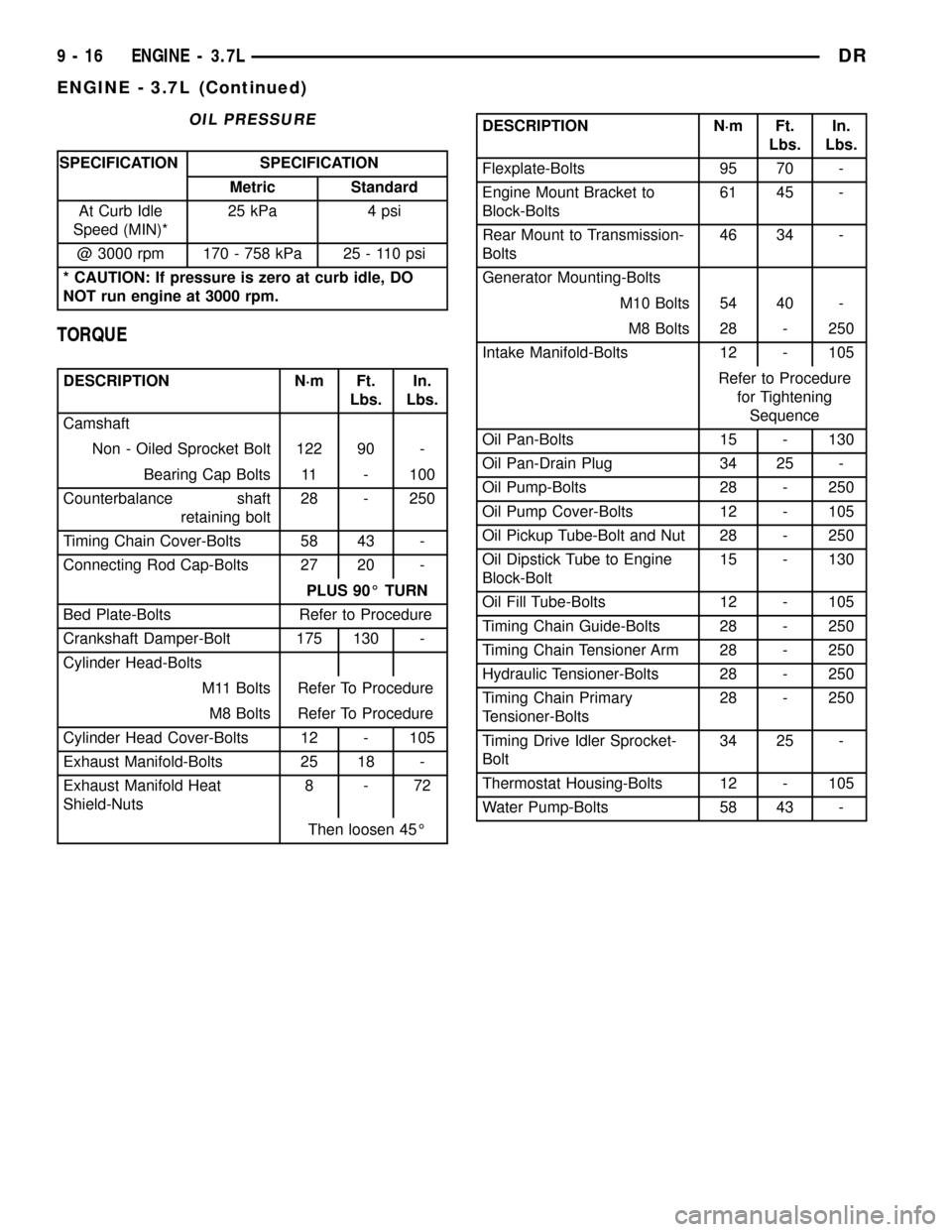
OIL PRESSURE
SPECIFICATION SPECIFICATION
Metric Standard
At Curb Idle
Speed (MIN)*25 kPa 4 psi
@ 3000 rpm 170 - 758 kPa 25 - 110 psi
* CAUTION: If pressure is zero at curb idle, DO
NOT run engine at 3000 rpm.
TORQUE
DESCRIPTION N´m Ft.
Lbs.In.
Lbs.
Camshaft
Non - Oiled Sprocket Bolt 122 90 -
Bearing Cap Bolts 11 - 100
Counterbalance shaft
retaining bolt28 - 250
Timing Chain Cover-Bolts 58 43 -
Connecting Rod Cap-Bolts 27 20 -
PLUS 90É TURN
Bed Plate-Bolts Refer to Procedure
Crankshaft Damper-Bolt 175 130 -
Cylinder Head-Bolts
M11 Bolts Refer To Procedure
M8 Bolts Refer To Procedure
Cylinder Head Cover-Bolts 12 - 105
Exhaust Manifold-Bolts 25 18 -
Exhaust Manifold Heat
Shield-Nuts8-72
Then loosen 45É
DESCRIPTION N´m Ft.
Lbs.In.
Lbs.
Flexplate-Bolts 95 70 -
Engine Mount Bracket to
Block-Bolts61 45 -
Rear Mount to Transmission-
Bolts46 34 -
Generator Mounting-Bolts
M10 Bolts 54 40 -
M8 Bolts 28 - 250
Intake Manifold-Bolts 12 - 105
Refer to Procedure
for Tightening
Sequence
Oil Pan-Bolts 15 - 130
Oil Pan-Drain Plug 34 25 -
Oil Pump-Bolts 28 - 250
Oil Pump Cover-Bolts 12 - 105
Oil Pickup Tube-Bolt and Nut 28 - 250
Oil Dipstick Tube to Engine
Block-Bolt15 - 130
Oil Fill Tube-Bolts 12 - 105
Timing Chain Guide-Bolts 28 - 250
Timing Chain Tensioner Arm 28 - 250
Hydraulic Tensioner-Bolts 28 - 250
Timing Chain Primary
Tensioner-Bolts28 - 250
Timing Drive Idler Sprocket-
Bolt34 25 -
Thermostat Housing-Bolts 12 - 105
Water Pump-Bolts 58 43 -
9 - 16 ENGINE - 3.7LDR
ENGINE - 3.7L (Continued)
Page 1262 of 2627

for this job. In addition to deglazing, it will reduce
taper and out-of-round, as well as removing light
scuffing, scoring and scratches. Usually, a few strokes
will clean up a bore and maintain the required lim-
its.
CAUTION: DO NOT use rigid type hones to remove
cylinder wall glaze.
(2) Deglazing of the cylinder walls may be done if
the cylinder bore is straight and round. Use a cylin-
der surfacing hone, Honing Tool C-3501, equipped
with 280 grit stones (C-3501-3810). about 20-60
strokes, depending on the bore condition, will be suf-
ficient to provide a satisfactory surface. Using honing
oil C-3501-3880, or a light honing oil, available from
major oil distributors.
CAUTION: DO NOT use engine or transmission oil,
mineral spirits, or kerosene.
(3) Honing should be done by moving the hone up
and down fast enough to get a crosshatch pattern.
The hone marks should INTERSECT at 50É to 60É
for proper seating of rings (Fig. 29).
(4) A controlled hone motor speed between 200 and
300 RPM is necessary to obtain the proper cross-
hatch angle. The number of up and down strokes per
minute can be regulated to get the desired 50É to 60É
angle. Faster up and down strokes increase the cross-
hatch angle.(5) After honing, it is necessary that the block be
cleaned to remove all traces of abrasive. Use a brush
to wash parts with a solution of hot water and deter-
gent. Dry parts thoroughly. Use a clean, white, lint-
free cloth to check that the bore is clean. Oil the
bores after cleaning to prevent rusting.
CLEANING
Thoroughly clean the oil pan and engine block gas-
ket surfaces.
Use compressed air to clean out:
²The galley at the oil filter adaptor hole.
²The front and rear oil galley holes.
²The feed holes for the crankshaft main bearings.
Once the block has been completely cleaned, apply
Loctite PST pipe sealant with Teflon 592 to the
threads of the front and rear oil galley plugs. Tighten
the 1/4 inch NPT plugs to 20 N´m (177 in. lbs.)
torque. Tighten the 3/8 inch NPT plugs to 27 N´m
(240 in. lbs.) torque.
INSPECTION
(1) It is mandatory to use a dial bore gauge to
measure each cylinder bore diameter. To correctly
select the proper size piston, a cylinder bore gauge,
capable of reading in 0.003 mm (.0001 in.) INCRE-
MENTS is required. If a bore gauge is not available,
do not use an inside micrometer (Fig. 30).
Fig. 29 CYLINDER BORE CROSSHATCH PATTERN
1 - CROSSHATCH PATTERN
2 - INTERSECT ANGLE
Fig. 30 BORE GAUGE-TYPICAL
1 - FRONT
2 - BORE GAUGE
3 - CYLINDER BORE
4 - 38 MM (1.5 in)
DRENGINE - 3.7L 9 - 39
ENGINE BLOCK (Continued)
Page 1269 of 2627

CRANKSHAFT OIL SEAL - FRONT
REMOVAL
(1) Disconnect negative cable from battery.
(2) Remove accessory drive belt (Refer to 7 -
COOLING/ACCESSORY DRIVE/DRIVE BELTS -
REMOVAL).
(3) Remove A/C compressor mouning fasteners and
set aside.
(4) Drain cooling system (Refer to 7 - COOLING -
STANDARD PROCEDURE).
(5) Remove upper radiator hose.
(6) Disconnect electrical connector for fan mounted
inside radiator shroud.
(7) Remove radiator shroud attaching fasteners.
NOTE: Transmission cooler line snaps into shroud
lower right hand corner.
(8)
Remove radiator cooling fan and shroud (Refer to
7 - COOLING/ENGINE/RADIATOR FAN - REMOVAL).
(9) Remove crankshaft damper bolt.
(10) Remove damper using Special Tools 8513
Insert and 1026 Three Jaw Puller (Fig. 37).
(11) Using Special Tool 8511, remove crankshaft
front seal (Fig. 38).
INSTALLATION
CAUTION: To prevent severe damage to the Crank-
shaft, Damper or Special Tool 8512, thoroughlyclean the damper bore and the crankshaft nose
before installing Damper.
(1) Using Special Tool 8348 and 8512, install
crankshaft front seal (Fig. 39).
(2) Install vibration damper (Refer to 9 - ENGINE/
ENGINE BLOCK/VIBRATION DAMPER - INSTAL-
LATION).
Fig. 37 Crankshaft Damper Removal
1 - SPECIAL TOOL 8513 INSERT
2 - SPECIAL TOOL 1026
Fig. 39 Crankshaft Front Seal Installation
1 - TIMING CHAIN COVER
2 - SPECIAL TOOL 8348
3 - SPECIAL TOOL 8512
Fig. 38 Crankshaft Front Seal Removal
1 - SPECIAL TOOL 8511
9 - 46 ENGINE - 3.7LDR