1998 DODGE RAM 1500 height
[x] Cancel search: heightPage 1347 of 2627

REMOVAL
NOTE: The cylinder heads must be removed in
order to perform this procedure.
(1) Remove rocker arms and lash adjusters(Refer
to 9 - ENGINE/CYLINDER HEAD/ROCKER ARM /
ADJUSTER ASSY - REMOVAL). (Fig. 41).
(2) Remove the camshaft bearing caps and the
camshaft.
NOTE: All six valve springs and valves are removed
in the same manner; this procedure only covers
one valve and valve spring.
(3) Using Special Tool C-3422±B or C-3422±C
Valve Spring Compressor and Special tool 8519
Adapter, compress the valve spring.
NOTE: It may be necessary to tap the top of the
valve spring to loosen the spring retainers locks
enough to be removed.
(4) Remove the two spring retainer lock halves.
NOTE: the valve spring is under tension use care
when releasing the valve spring compressor.
(5) Remove the valve spring compressor.
(6) Remove the spring retainer, and the spring.NOTE: Check for sharp edges on the keeper
grooves. Remove any burrs from the valve stem
before removing the valve from the cylinder head.
(7) Remove the valve from the cylinder head.
NOTE: The valve stem seals are common between
intake and exhaust.
(8) Remove the valve stem seal. Mark the valve for
proper installation.
TESTING VALVE SPRINGS
NOTE: Whenever the valves are removed from the
cylinder head it is recommended that the valve
springs be inspected and tested for reuse.
Inspect the valve springs for physical signs of wear
or damage. Turn table of tool C-647 until surface is
in line with the 40.12 mm (1.579 in.) mark on the
threaded stud and the zero mark on the front. Place
spring over the stud on the table and lift compress-
ing lever to set tone device. Pull on torque wrench
until a Ping is heard. Take reading on torque wrench
at this instant. Multiply this reading by two. This
will give the spring load at test length. Fractional
measurements are indicated on the table for finer
adjustments. Refer to Specifications Section to obtain
specified height and allowable tensions. Replace any
springs that do not meet specifications (Fig. 42).
INSTALLATION
(1) coat the valve stem with clean engine oil and
insert it into the cylinder head.
(2) Install the valve stem seal. make sure the seal
is fully seated and that the garter spring at the top
of the seal is intact.
Fig. 41 Rocker Arm Removal
1 - CAMSHAFT
2 - SPECIAL TOOL 8516
Fig. 42 Testing Valve Springs
1 - SPECIAL TOOL C-647
9 - 124 ENGINE - 4.7LDR
INTAKE/EXHAUST VALVES & SEATS (Continued)
Page 1418 of 2627
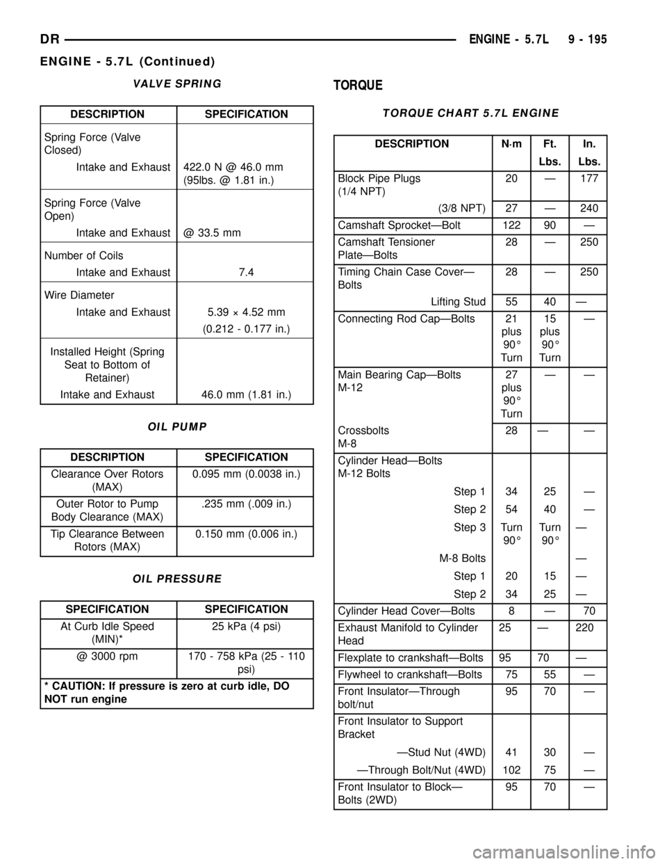
VALVE SPRING
DESCRIPTION SPECIFICATION
Spring Force (Valve
Closed)
Intake and Exhaust 422.0 N @ 46.0 mm
(95lbs. @ 1.81 in.)
Spring Force (Valve
Open)
Intake and Exhaust @ 33.5 mm
Number of Coils
Intake and Exhaust 7.4
Wire Diameter
Intake and Exhaust 5.39 ý 4.52 mm
(0.212 - 0.177 in.)
Installed Height (Spring
Seat to Bottom of
Retainer)
Intake and Exhaust 46.0 mm (1.81 in.)
OIL PUMP
DESCRIPTION SPECIFICATION
Clearance Over Rotors
(MAX)0.095 mm (0.0038 in.)
Outer Rotor to Pump
Body Clearance (MAX).235 mm (.009 in.)
Tip Clearance Between
Rotors (MAX)0.150 mm (0.006 in.)
OIL PRESSURE
SPECIFICATION SPECIFICATION
At Curb Idle Speed
(MIN)*25 kPa (4 psi)
@ 3000 rpm 170 - 758 kPa (25 - 110
psi)
* CAUTION: If pressure is zero at curb idle, DO
NOT run engine
TORQUE
TORQUE CHART 5.7L ENGINE
DESCRIPTION N´m Ft. In.
Lbs. Lbs.
Block Pipe Plugs
(1/4 NPT)20 Ð 177
(3/8 NPT) 27 Ð 240
Camshaft SprocketÐBolt 122 90 Ð
Camshaft Tensioner
PlateÐBolts28 Ð 250
Timing Chain Case CoverÐ
Bolts28 Ð 250
Lifting Stud 55 40 Ð
Connecting Rod CapÐBolts 21
plus
90É
Turn15
plus
90É
TurnÐ
Main Bearing CapÐBolts
M-1227
plus
90É
TurnÐÐ
Crossbolts
M-828 Ð Ð
Cylinder HeadÐBolts
M-12 Bolts
Step 1 34 25 Ð
Step 2 54 40 Ð
Step 3 Turn
90ÉTurn
90ÉÐ
M-8 Bolts Ð
Step 1 20 15 Ð
Step 2 34 25 Ð
Cylinder Head CoverÐBolts 8 Ð 70
Exhaust Manifold to Cylinder
Head25 Ð 220
Flexplate to crankshaftÐBolts 95 70 Ð
Flywheel to crankshaftÐBolts 75 55 Ð
Front InsulatorÐThrough
bolt/nut95 70 Ð
Front Insulator to Support
Bracket
ÐStud Nut (4WD) 41 30 Ð
ÐThrough Bolt/Nut (4WD) 102 75 Ð
Front Insulator to BlockÐ
Bolts (2WD)95 70 Ð
DRENGINE - 5.7L 9 - 195
ENGINE - 5.7L (Continued)
Page 1425 of 2627
INTAKE/EXHAUST VALVES &
SEATS
DESCRIPTION
DESCRIPTION - VALVE GUIDES
The valve guides are made of powered metal and
are pressed into the cylinder head. The guides are
not replaceable or serviceable, and valve guide ream-
ing is not recommended. If the guides are worn
beyond acceptable limits, replace the cylinder heads.
DESCRIPTION
Both the intake and exhaust valves are made of
steel. The intake valve is 50.93 mm (2.00 inches) in
diameter and the exhaust valve is 39.53 mm (1.55
inches) in diameter. All valves use three bead lock
keepers to retain the springs and promote valve rota-
tion.
STANDARD PROCEDURE - REFACING
NOTE: Valve seats that are worn or burned can be
reworked, provided that correct angle and seat
width are maintained. Otherwise the cylinder head
must be replaced.
NOTE: When refacing valves and valve seats, it is
important that the correct size valve guide pilot be
used for reseating stones. A true and complete sur-
face must be obtained.
(1) Using a suitable dial indicator measure the
center of the valve seat Total run out must not
exceed 0.051 mm (0.002 in).
(2) Apply a small amount of Prussian blue to the
valve seat, insert the valve into the cylinder head,
while applying light pressure on the valve rotate the
valve. Remove the valve and examine the valve face.
If the blue is transferred below the top edge of the
valve face, lower the valve seat using a 15 degree
stone. If the blue is transferred to the bottom edge of
the valve face, raise the valve seat using a 65 degree
stone.
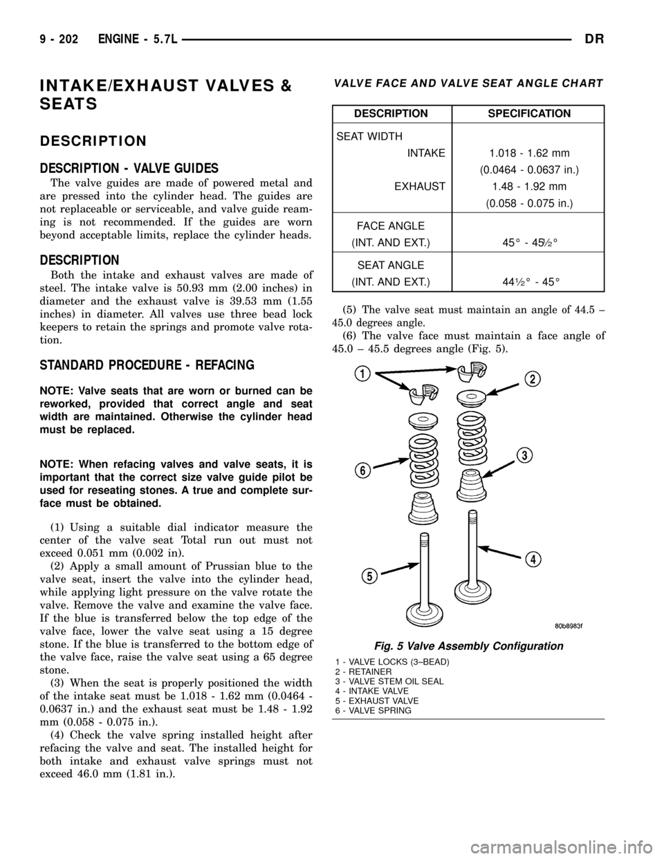
(3) When the seat is properly positioned the width
of the intake seat must be 1.018 - 1.62 mm (0.0464 -
0.0637 in.) and the exhaust seat must be 1.48 - 1.92
mm (0.058 - 0.075 in.).
(4) Check the valve spring installed height after
refacing the valve and seat. The installed height for
both intake and exhaust valve springs must not
exceed 46.0 mm (1.81 in.).
VALVE FACE AND VALVE SEAT ANGLE CHART
DESCRIPTION SPECIFICATION
SEAT WIDTH
INTAKE 1.018 - 1.62 mm
(0.0464 - 0.0637 in.)
EXHAUST 1.48 - 1.92 mm
(0.058 - 0.075 in.)
FACE ANGLE
(INT. AND EXT.) 45É - 45
1¤2É
SEAT ANGLE
(INT. AND EXT.) 44
1¤2É - 45É
(5)
The valve seat must maintain an angle of 44.5 ±
45.0 degrees angle.
(6) The valve face must maintain a face angle of
45.0 ± 45.5 degrees angle (Fig. 5).
Fig. 5 Valve Assembly Configuration
1 - VALVE LOCKS (3±BEAD)
2 - RETAINER
3 - VALVE STEM OIL SEAL
4 - INTAKE VALVE
5 - EXHAUST VALVE
6 - VALVE SPRING
9 - 202 ENGINE - 5.7LDR
Page 1426 of 2627

REMOVAL
(1) Remove the cylinder head (Refer to 9 -
ENGINE/CYLINDER HEAD - REMOVAL).
(2) Compress valve springs using Valve Spring
Compressor Tool special tool # C-3422and adapter
8464.
(3) Remove valve retaining locks, valve spring
retainers, valve stem seals and valve springs.
(4) Before removing valves, remove any burrs from
valve stem lock grooves to prevent damage to the
valve guides. Identify valves to ensure installation in
original location.
INSTALLATION
(1) Clean valves thoroughly. Discard burned,
warped and cracked valves.
(2) Remove carbon and varnish deposits from
inside of valve guides with a reliable guide cleaner.
(3) Measure valve stems for wear. If wear exceeds
0.051 mm (0.002 inch), replace the valve.
(4) Coat valve stems with lubrication oil and insert
them in cylinder head.
(5) If valves or seats are reground, check valve
stem height. If valve is too long, replace cylinder
head.
(6) Install new seals on all valve guides. Install
valve springs and valve retainers.
(7) Compress valve springs with Valve Spring
Compressor Tool special tool # C- 3422and adapter
8464, install locks and release tool. If valves and/or
seats are ground, measure the installed height of
springs. Make sure the measurement is taken from
bottom of spring seat in cylinder head to the bottom
surface of spring retainer.
(8) Install cylinder head (Refer to 9 - ENGINE/
CYLINDER HEAD - INSTALLATION).
ROCKER ARM / ADJUSTER
ASSY
REMOVAL
(1) Remove cylinder head cover.(Refer to 9 -
ENGINE/CYLINDER HEAD/CYLINDER HEAD
COVER(S) - REMOVAL)
(2) Loosen the rocker shafts using the following
sequence:Center, center-left, center-right, left,
right,.
CAUTION: The rocker shaft assemblies are not
interchangeable between intake and exhaust. The
intake rocker arms are marked with an ªIº.
(3) Remove the rocker shafts. Note location for
reassembly.CAUTION: The longer push rods are for the exhaust
side, and the shorter push rods are for intake side.
(4) Remove the pushrods. Note pushrod location
for reassembly.
INSTALLATION
CAUTION: The longer push rods are for the exhaust
side, and the shorter push rods are for intake side.
(1) Install the push rods in the same order as
removed.
CAUTION: Verify that pushrod is installed into
rocker arm and lifter correctly while installing
rocker shaft assembly. Recheck after rocker shaft
has been torqued to specification.
CAUTION: The rocker shaft assemblies are not
interchangeable between intake and exhaust. The
intake rocker arms are marked with the letter ªIº.
(2) Install rocker shaft assemblies in the same
order as removed.
CAUTION: Ensure that hold downs and rocker arms
are not overlapped when torquing bolts.
(3) Tighten the rocker shaft bolts to 22 N´m (195
in. lbs.) torque,using the following sequence:Center,
center-right, center-left, right, left.
CAUTION: DO NOT rotate or crank the engine dur-
ing or immediately after rocker arm installation.
Allow the hydraulic roller tappets adequate time to
bleed down (about 5 minutes).
(4) Install cylinder head cover (Refer to 9 -
ENGINE/CYLINDER HEAD/CYLINDER HEAD
COVER(S) - INSTALLATION).
VALVE STEM SEALS
DESCRIPTION
The valve guide seals are made of rubber and
incorporate an integral steel valve spring seat. The
integral garter spring maintains consistent lubrica-
tion control to the valve stems.
DRENGINE - 5.7L 9 - 203
INTAKE/EXHAUST VALVES & SEATS (Continued)
Page 1517 of 2627

OIL PRESSURE RELIEF VALVE
REMOVAL
(1) Disconnect the battery negative cables.
(2) Remove the threaded plug, spring and plunger
(Fig. 108). Insert a finger or a seal pick to lift the
plunger from the bore.
NOTE: If the plunger is stuck in the bore, it will be
necessary to remove the filter head.
CLEANING
(1) Clean the regulator spring and plunger with a
suitable solvent and blow dry with compressed air. If
the plunger bore requires cleaning, it is necessary to
remove the oil filter head to avoid getting debris into
the engine.
INSPECTION
Inspect the plunger and plunger bore for cracks
and excessive wear. Polished surfaces are acceptable.
Verify that the plunger moves freely in the bore.
Check the spring for height and load limitations
(Fig. 109). Replace the spring if out of limits shown
in the figure.
INSTALLATION
(1) Install the plunger, spring, and plug as shown
in (Fig. 108). Tighten the plug to 80 N´m (59 ft. lbs.)
torque.
(2) Connect the battery negative cables.
(3) Start the engine and verify that it has oil pres-
sure.
OIL PRESSURE SWITCH
REMOVAL
(1) Disconnect the battery negative cables.
(2) Disconnect the oil pressure switch connector.
(3) Using a suitable socket, remove the oil pres-
sure switch from the block (counter-clockwise).
INSTALLATION
(1) If the switch is not being replaced, replace and
lubricate the o-ring.
(2) Install the oil pressure switch and tighten to
18 N´m (159 in. lbs.) torque.
(3) Connect oil pressure switch connector.
(4) Connect the battery negative cables.
(5) Start engine and check for oil leaks at the
switch.
OIL PUMP
REMOVAL
(1) Disconnect the battery negative cables.
(2) Remove fan/drive assembly (Refer to 7 - COOL-
ING/ENGINE/RADIATOR FAN - REMOVAL).
(3) Remove the accessory drive belt (Refer to 7 -
COOLING/ACCESSORY DRIVE/DRIVE BELTS -
REMOVAL).
(4) Remove the fan support/hub assembly.
(5) Remove crankshaft damper (Refer to 9 -
ENGINE/ENGINE BLOCK/VIBRATION DAMPER -
REMOVAL) and speed indicator ring.
(6) Remove power steering pump.
(7) Remove accessory drive belt tensioner.
(8) Remove the gear housing cover (Refer to 9 -
ENGINE/VALVE TIMING/GEAR HOUSING COVER
- REMOVAL).
Fig. 108 Oil Pressure Regulator
1 - OIL FILTER
2 - PLUG
3 - GASKET
4 - SPRING
5 - VALVE
Fig. 109 Oil Pressure Regulator Spring Check
9 - 294 ENGINE 5.9L DIESELDR
Page 1553 of 2627

SERVICE SLEEVE ASSEMBLY
NOTE: Two sleeve halves are included with each
kit. Modifications as follow, are necessary to create
the correct sleeve assembly for each application.
(1) On 4X2 models, the9lower9sleeve is made by
cutting off the tab and cutting out a notch in the bot-
tom sleeve portion. Round the corners of the cut out
to keep stress cracks from forming. On 4X4 models
the9lower9sleeve is used as provided. (Fig. 15)
(2) On both 4X2 and 4X4 models cut off the front
tab on the upper sleeve portion. (Fig. 16)(3) The sleeve halves are shipped slightly over-
sized to allow custom fitting to each replacement
frame rail tip. It is necessary to grind the mating
surfaces to achieve the desired snug fit into the
replacement tip (rail tube has increasing height rear-
ward of the cut line). Once the two sleeve halves are
fitted, bevel the edges 25É - 30É.
NOTE: Scribing a line 2 mm from the cut edge and
then grinding back to the mark will simplify the
bevel creation process and accuracy.
(4) Remove any burrs at the beveled edges.
(5) Using the Weld Process Specifications table
(Refer to 13 - FRAME & BUMPERS/FRAME - SPEC-
IFICATIONS - WELDING), weld the two halves of
the repair sleeve together. (Fig. 17)
(6) Clean the welds of any flux and other impuri-
ties and grind smooth before proceeding with the
installation of the sleeve.
(7) Find the centerline of the sleeve and scribe a
centerline mark. Mark two additional lines 2 mm
(0.08 in.) on either side of the centerline mark to help
ensure the required 4 mm-6mm(0.16 in. - 0.24 in.)
weld root gap. (Fig. 17)
Fig. 15 4X2 LOWER SLEEVE CUT LOCATION
1 - SERVICE SLEEVE LOWER HALF
2 - CUT DIMENSION 27 mm (1.06 in.)
3 - CUT DIMENSION 36.1 mm (1.42 in)
4 - 4X2 CUTOUT
5 - FRONT TAB CUT LINE (4X2 ONLY)
Fig. 16 UPPER SLEEVE CUT LOCATION
1 - SERVICE SLEEVE UPPER HALF
2 - CUT LOCATION
Fig. 17 SERVICE SLEEVE ASSEMBLY
1 - CENTERLINE SCRIBE MARK
2 - WELD SEAM
3 - REAR TAB (4X4 ONLY)
4 - SCRIBE LINE LOCATION 2 mm (0.08 in.)
5 - FRONT TAB (4X4 ONLY)
13 - 10 FRAMES & BUMPERSDR
FRAME (Continued)
Page 1559 of 2627
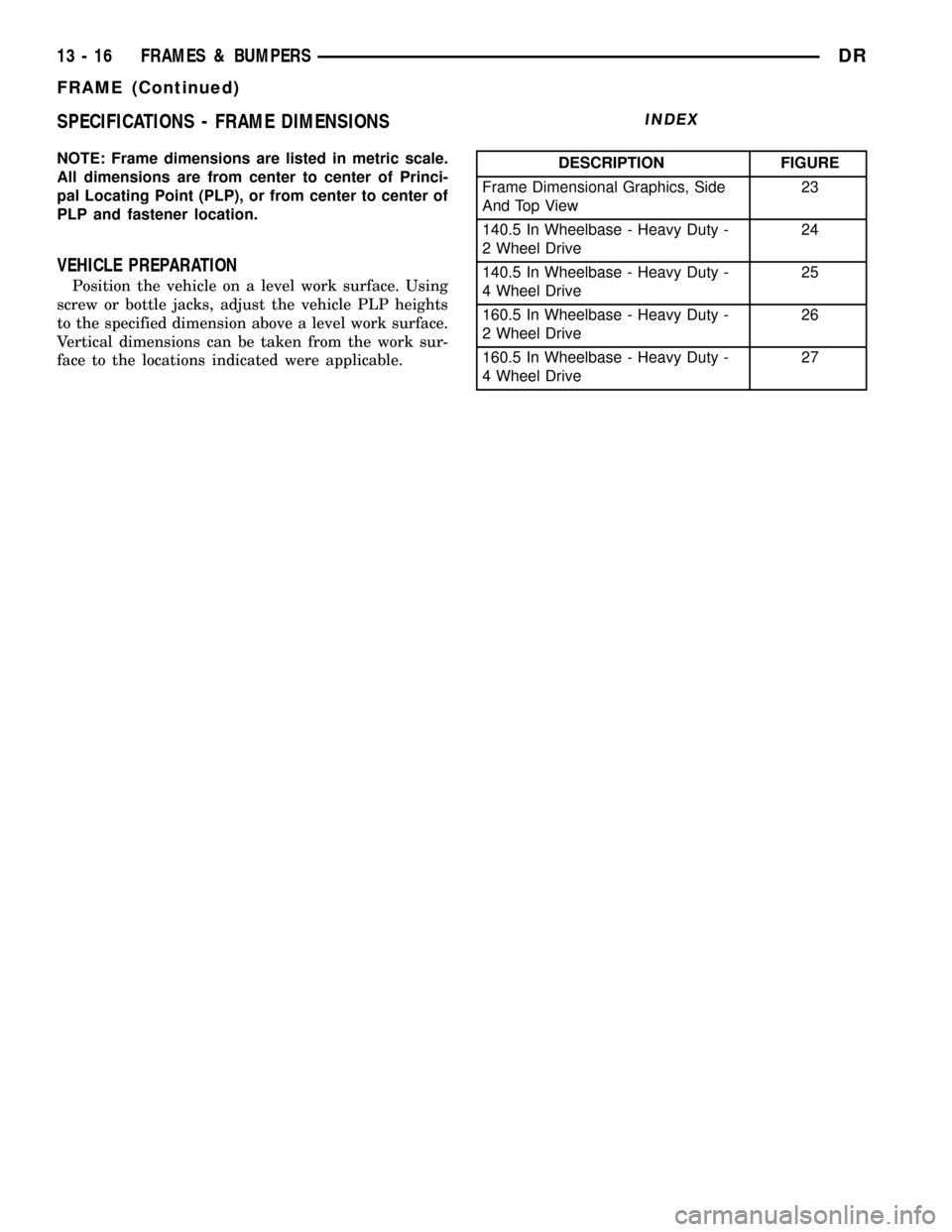
SPECIFICATIONS - FRAME DIMENSIONS
NOTE: Frame dimensions are listed in metric scale.
All dimensions are from center to center of Princi-
pal Locating Point (PLP), or from center to center of
PLP and fastener location.
VEHICLE PREPARATION
Position the vehicle on a level work surface. Using
screw or bottle jacks, adjust the vehicle PLP heights
to the specified dimension above a level work surface.
Vertical dimensions can be taken from the work sur-
face to the locations indicated were applicable.
INDEX
DESCRIPTION FIGURE
Frame Dimensional Graphics, Side
And Top View23
140.5 In Wheelbase - Heavy Duty -
2 Wheel Drive24
140.5 In Wheelbase - Heavy Duty -
4 Wheel Drive25
160.5 In Wheelbase - Heavy Duty -
2 Wheel Drive26
160.5 In Wheelbase - Heavy Duty -
4 Wheel Drive27
13 - 16 FRAMES & BUMPERSDR
FRAME (Continued)
Page 1597 of 2627

REMOVAL
The fuel pump relay is located in the Power Distri-
bution Center (PDC) (Fig. 13). Refer to label on PDC
cover for relay location.
(1) Remove PDC cover.
(2) Remove relay from PDC.
(3) Check condition of relay terminals and PDC
connector terminals for damage or corrosion. Repair
if necessary before installing relay.
(4) Check for pin height (pin height should be the
same for all terminals within the PDC connector).
Repair if necessary before installing relay.
INSTALLATION
The fuel pump relay is located in the Power Distri-
bution Center (PDC). Refer to label on PDC cover for
relay location.
(1) Install relay to PDC.
(2) Install cover to PDC.
IDLE AIR CONTROL MOTOR
DESCRIPTION
A separate IAC motor is not used with the 5.7L V-8
engine.
The IAC stepper motor is mounted to the throttle
body, and regulates the amount of air bypassing the
control of the throttle plate. As engine loads and
ambient temperatures change, engine rpm changes.
A pintle on the IAC stepper motor protrudes into apassage in the throttle body, controlling air flow
through the passage. The IAC is controlled by the
Powertrain Control Module (PCM) to maintain the
target engine idle speed.
OPERATION
A separate IAC motor is not used with the 5.7L V-8
engine.
At idle, engine speed can be increased by retract-
ing the IAC motor pintle and allowing more air to
pass through the port, or it can be decreased by
restricting the passage with the pintle and diminish-
ing the amount of air bypassing the throttle plate.
The IAC is called a stepper motor because it is
moved (rotated) in steps, or increments. Opening the
IAC opens an air passage around the throttle blade
which increases RPM.
The PCM uses the IAC motor to control idle speed
(along with timing) and to reach a desired MAP dur-
ing decel (keep engine from stalling).
The IAC motor has 4 wires with 4 circuits. Two of
the wires are for 12 volts and ground to supply elec-
trical current to the motor windings to operate the
stepper motor in one direction. The other 2 wires are
also for 12 volts and ground to supply electrical cur-
rent to operate the stepper motor in the opposite
direction.
To make the IAC go in the opposite direction, the
PCM just reverses polarity on both windings. If only
1 wire is open, the IAC can only be moved 1 step
(increment) in either direction. To keep the IAC
motor in position when no movement is needed, the
PCM will energize both windings at the same time.
This locks the IAC motor in place.
In the IAC motor system, the PCM will count
every step that the motor is moved. This allows the
PCM to determine the motor pintle position. If the
memory is cleared, the PCM no longer knows the
position of the pintle. So at the first key ON, the
PCM drives the IAC motor closed, regardless of
where it was before. This zeros the counter. From
this point the PCM will back out the IAC motor and
keep track of its position again.
When engine rpm is above idle speed, the IAC is
used for the following:
²Off-idle dashpot (throttle blade will close quickly
but idle speed will not stop quickly)
²Deceleration air flow control
²A/C compressor load control (also opens the pas-
sage slightly before the compressor is engaged so
that the engine rpm does not dip down when the
compressor engages)
²Power steering load control
The PCM can control polarity of the circuit to con-
trol direction of the stepper motor.
Fig. 13 PDC LOCATION
1 - BATTERY
2 - INTEGRATED POWER MODULE (IPM)
14 - 28 FUEL INJECTION - GASDR
FUEL PUMP RELAY (Continued)