1998 DODGE RAM 1500 lock
[x] Cancel search: lockPage 1604 of 2627
(4) Install MAP sensor mounting bolts (screws).
Refer to Torque Specifications.
(5) Connect electrical connector.
5.7L V-8
The Manifold Absolute Pressure (MAP) sensor is
mounted to the front of the intake manifold air ple-
num box (Fig. 24).
(1) Clean MAP sensor mounting hole at intake
manifold.
(2) Check MAP sensor o-ring seal for cuts or tears.
(3) Position sensor into manifold.
(4) Rotate sensor 1/4 turn clockwise for installa-
tion.
(5) Connect electrical connector.
OXYGEN SENSOR
DESCRIPTION
The Oxygen Sensors (O2S) are attached to, and
protrude into the vehicle exhaust system. Depending
on the engine or emission package, the vehicle may
use a total of either 2 or 4 sensors.
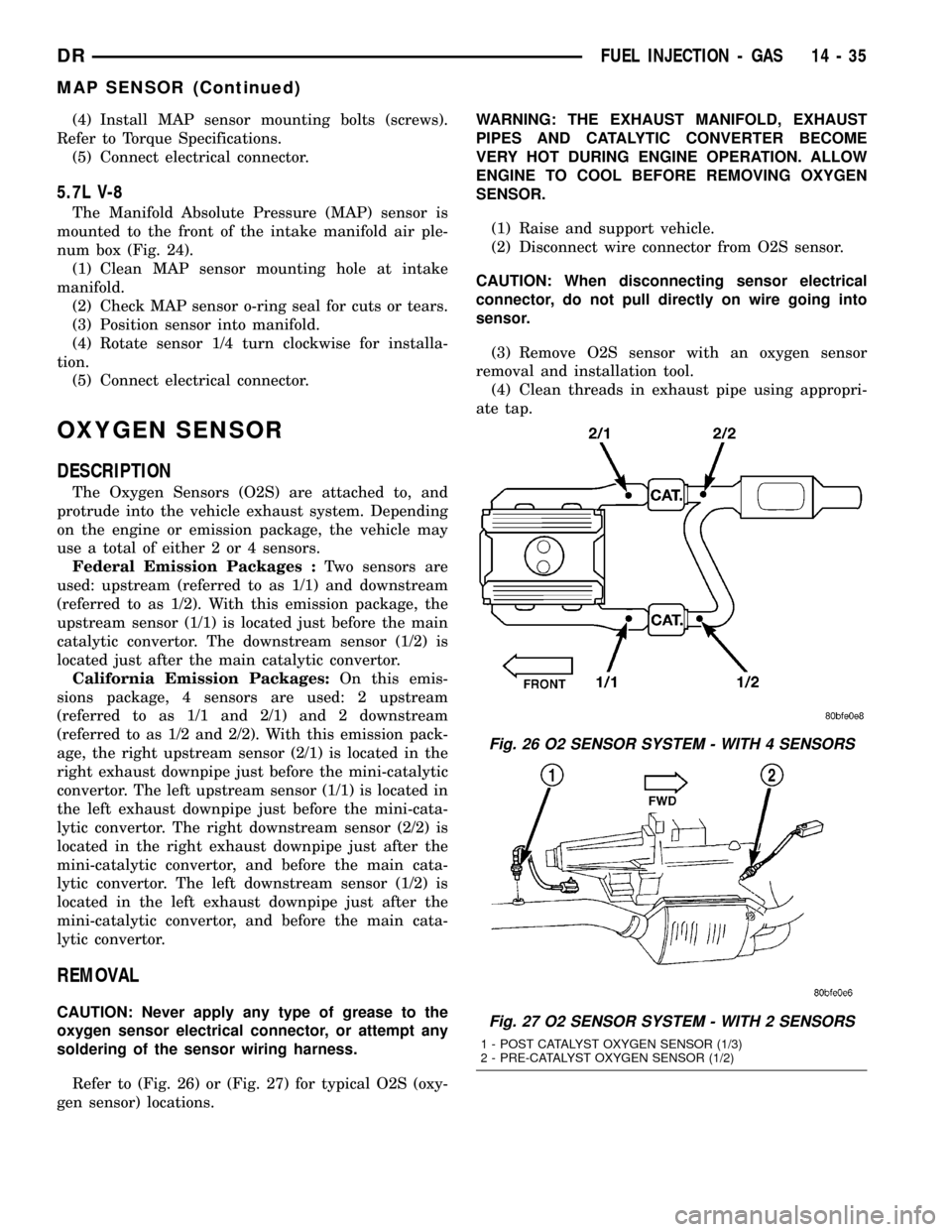
Federal Emission Packages :Two sensors are
used: upstream (referred to as 1/1) and downstream
(referred to as 1/2). With this emission package, the
upstream sensor (1/1) is located just before the main
catalytic convertor. The downstream sensor (1/2) is
located just after the main catalytic convertor.
California Emission Packages:On this emis-
sions package, 4 sensors are used: 2 upstream
(referred to as 1/1 and 2/1) and 2 downstream
(referred to as 1/2 and 2/2). With this emission pack-
age, the right upstream sensor (2/1) is located in the
right exhaust downpipe just before the mini-catalytic
convertor. The left upstream sensor (1/1) is located in
the left exhaust downpipe just before the mini-cata-
lytic convertor. The right downstream sensor (2/2) is
located in the right exhaust downpipe just after the
mini-catalytic convertor, and before the main cata-
lytic convertor. The left downstream sensor (1/2) is
located in the left exhaust downpipe just after the
mini-catalytic convertor, and before the main cata-
lytic convertor.
REMOVAL
CAUTION: Never apply any type of grease to the
oxygen sensor electrical connector, or attempt any
soldering of the sensor wiring harness.
Refer to (Fig. 26) or (Fig. 27) for typical O2S (oxy-
gen sensor) locations.WARNING: THE EXHAUST MANIFOLD, EXHAUST
PIPES AND CATALYTIC CONVERTER BECOME
VERY HOT DURING ENGINE OPERATION. ALLOW
ENGINE TO COOL BEFORE REMOVING OXYGEN
SENSOR.
(1) Raise and support vehicle.
(2) Disconnect wire connector from O2S sensor.
CAUTION: When disconnecting sensor electrical
connector, do not pull directly on wire going into
sensor.
(3) Remove O2S sensor with an oxygen sensor
removal and installation tool.
(4) Clean threads in exhaust pipe using appropri-
ate tap.
Fig. 26 O2 SENSOR SYSTEM - WITH 4 SENSORS
Fig. 27 O2 SENSOR SYSTEM - WITH 2 SENSORS
1 - POST CATALYST OXYGEN SENSOR (1/3)
2 - PRE-CATALYST OXYGEN SENSOR (1/2)
DRFUEL INJECTION - GAS 14 - 35
MAP SENSOR (Continued)
Page 1617 of 2627
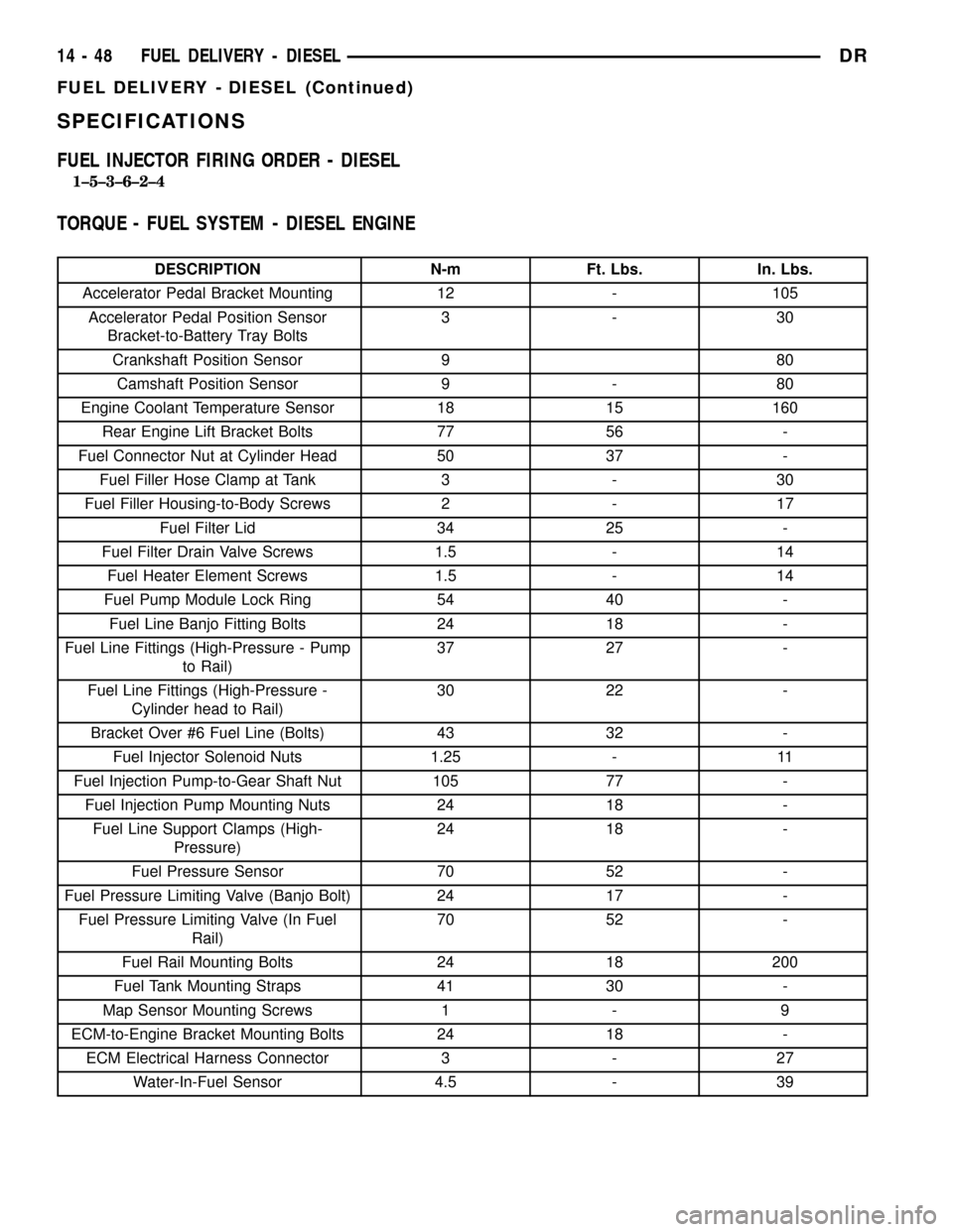
SPECIFICATIONS
FUEL INJECTOR FIRING ORDER - DIESEL
1±5±3±6±2±4
TORQUE - FUEL SYSTEM - DIESEL ENGINE
DESCRIPTION N-m Ft. Lbs. In. Lbs.
Accelerator Pedal Bracket Mounting 12 - 105
Accelerator Pedal Position Sensor
Bracket-to-Battery Tray Bolts3-30
Crankshaft Position Sensor 9 80
Camshaft Position Sensor 9 - 80
Engine Coolant Temperature Sensor 18 15 160
Rear Engine Lift Bracket Bolts 77 56 -
Fuel Connector Nut at Cylinder Head 50 37 -
Fuel Filler Hose Clamp at Tank 3 - 30
Fuel Filler Housing-to-Body Screws 2 - 17
Fuel Filter Lid 34 25 -
Fuel Filter Drain Valve Screws 1.5 - 14
Fuel Heater Element Screws 1.5 - 14
Fuel Pump Module Lock Ring 54 40 -
Fuel Line Banjo Fitting Bolts 24 18 -
Fuel Line Fittings (High-Pressure - Pump
to Rail)37 27 -
Fuel Line Fittings (High-Pressure -
Cylinder head to Rail)30 22 -
Bracket Over #6 Fuel Line (Bolts) 43 32 -
Fuel Injector Solenoid Nuts 1.25 - 11
Fuel Injection Pump-to-Gear Shaft Nut 105 77 -
Fuel Injection Pump Mounting Nuts 24 18 -
Fuel Line Support Clamps (High-
Pressure)24 18 -
Fuel Pressure Sensor 70 52 -
Fuel Pressure Limiting Valve (Banjo Bolt) 24 17 -
Fuel Pressure Limiting Valve (In Fuel
Rail)70 52 -
Fuel Rail Mounting Bolts 24 18 200
Fuel Tank Mounting Straps 41 30 -
Map Sensor Mounting Screws 1 - 9
ECM-to-Engine Bracket Mounting Bolts 24 18 -
ECM Electrical Harness Connector 3 - 27
Water-In-Fuel Sensor 4.5 - 39
14 - 48 FUEL DELIVERY - DIESELDR
FUEL DELIVERY - DIESEL (Continued)
Page 1619 of 2627
FUEL FILTER / WATER
SEPARATOR
DESCRIPTION
The fuel filter/water separator assembly is located
on left side of engine above the starter motor. The
assembly also includes the fuel heater, Water-In-Fuel
(WIF) sensor, and fuel transfer pump.
OPERATION
The fuel filter/water separator protects the fuel
injection pump by removing water and contaminants
from the fuel. The construction of the filter/separator
allows fuel to pass through it, but helps prevent
moisture (water) from doing so. Moisture collects at
the bottom of the canister.
Refer to the maintenance schedules in the owners
manual for the recommended fuel filter replacement
intervals.
For draining of water from canister, refer to Fuel
Filter/Water Separator Removal/Installation section.
A Water-In-Fuel (WIF) sensor is attached to the
side of fuel filter housing. Refer to Water-In-Fuel
Sensor Description/Operation.
The fuel heater is installed into the top of the fil-
ter/separator housing. Refer to Fuel Heater Descrip-
tion/Operation.
REMOVAL
Refer to maintenance schedules in this manual, or
the owners manual for recommended fuel filter
replacement intervals.
Draining water from fuel filter/water separa-
tor housing:
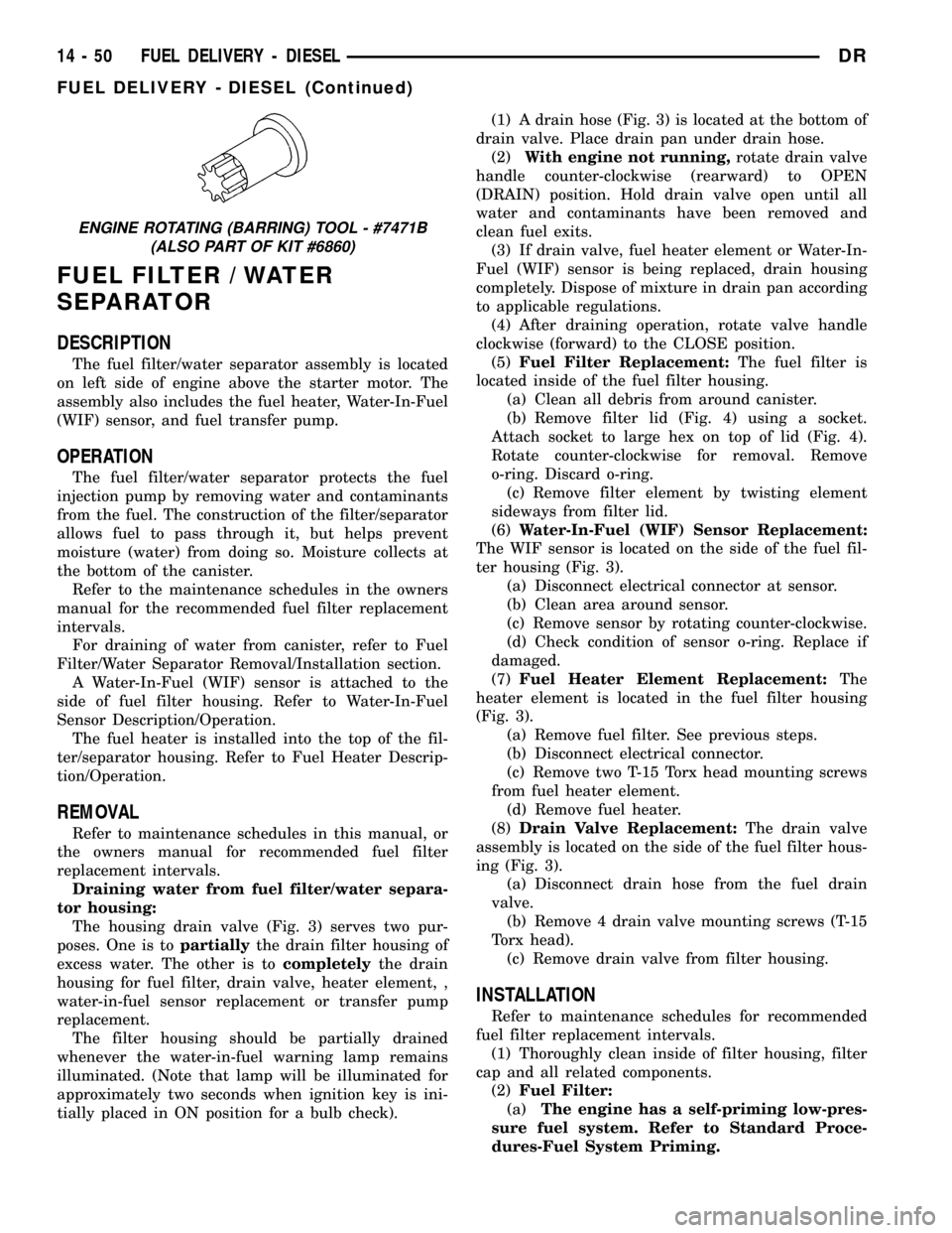
The housing drain valve (Fig. 3) serves two pur-
poses. One is topartiallythe drain filter housing of
excess water. The other is tocompletelythe drain
housing for fuel filter, drain valve, heater element, ,
water-in-fuel sensor replacement or transfer pump
replacement.
The filter housing should be partially drained
whenever the water-in-fuel warning lamp remains
illuminated. (Note that lamp will be illuminated for
approximately two seconds when ignition key is ini-
tially placed in ON position for a bulb check).(1) A drain hose (Fig. 3) is located at the bottom of
drain valve. Place drain pan under drain hose.
(2)With engine not running,rotate drain valve
handle counter-clockwise (rearward) to OPEN
(DRAIN) position. Hold drain valve open until all
water and contaminants have been removed and
clean fuel exits.
(3) If drain valve, fuel heater element or Water-In-
Fuel (WIF) sensor is being replaced, drain housing
completely. Dispose of mixture in drain pan according
to applicable regulations.
(4) After draining operation, rotate valve handle
clockwise (forward) to the CLOSE position.
(5)Fuel Filter Replacement:The fuel filter is
located inside of the fuel filter housing.
(a) Clean all debris from around canister.
(b) Remove filter lid (Fig. 4) using a socket.
Attach socket to large hex on top of lid (Fig. 4).
Rotate counter-clockwise for removal. Remove
o-ring. Discard o-ring.
(c) Remove filter element by twisting element
sideways from filter lid.
(6)Water-In-Fuel (WIF) Sensor Replacement:
The WIF sensor is located on the side of the fuel fil-
ter housing (Fig. 3).
(a) Disconnect electrical connector at sensor.
(b) Clean area around sensor.
(c) Remove sensor by rotating counter-clockwise.
(d) Check condition of sensor o-ring. Replace if
damaged.
(7)Fuel Heater Element Replacement:The
heater element is located in the fuel filter housing
(Fig. 3).
(a) Remove fuel filter. See previous steps.
(b) Disconnect electrical connector.
(c) Remove two T-15 Torx head mounting screws
from fuel heater element.
(d) Remove fuel heater.
(8)Drain Valve Replacement:The drain valve
assembly is located on the side of the fuel filter hous-
ing (Fig. 3).
(a) Disconnect drain hose from the fuel drain
valve.
(b) Remove 4 drain valve mounting screws (T-15
Torx head).
(c) Remove drain valve from filter housing.
INSTALLATION
Refer to maintenance schedules for recommended
fuel filter replacement intervals.
(1) Thoroughly clean inside of filter housing, filter
cap and all related components.
(2)Fuel Filter:
(a)The engine has a self-priming low-pres-
sure fuel system. Refer to Standard Proce-
dures-Fuel System Priming.
ENGINE ROTATING (BARRING) TOOL - #7471B
(ALSO PART OF KIT #6860)
14 - 50 FUEL DELIVERY - DIESELDR
FUEL DELIVERY - DIESEL (Continued)
Page 1620 of 2627

(b) Install new o-ring to canister lid and lubri-
cate o-ring with clean engine oil.
(c) Position new element to canister lid. Place
this assembly into canister by rotating clockwise.
(d) Tighten cap to 34 N´m (25 ft. lbs.) torque. Do
not overtighten cap.
(3)Water-In-Fuel (WIF) Sensor:
(a) Install new o-ring seal to WIF sensor.
(b) Apply a light film of clean oil to o-ring seal.
(c) Install sensor into housing.
(d) Tighten sensor to 2.5 N´m (25 in. lbs.) torque.
(e) Connect electrical connector to WIF sensor.
(4)Fuel Heater Element:
(a) Install fuel heater into fuel filter housing.
(b) Install fuel heater thermostat into fuel filter
housing.
(c) Install fuel heater mounting screws and
tighten to 1-1.5 N´m (13 in. lbs.) torque.
(d) Connect electrical connector to fuel heater
thermostat.
(e) Install new filter cover O-ring onto fuel filter
housing cover and lubricate with clean engine oil.
(f) Tighten fuel filter housing cover (lid) to 34
N´m (25 ft. lbs.).
(5)Drain Valve:
(a) Install 2 new o-rings to valve and filter hous-
ing.
(b) Lubricate with silicon grease.
(c) Install fuel drain valve.
(d) Install 4 mounting screws and tighten to
1±1.5 N´m (8±13 in. lbs.) torque.
(e) Connect drain hose to drain valve.
(6) Start engine and check for leaks.
FUEL HEATER
DESCRIPTION
The fuel heater assembly is located on the side of
the fuel filter housing (Fig. 3).
The heater/element assembly is equipped with a
temperature sensor (thermostat) that senses fuel
temperature. This sensor is attached to the fuel heat-
er/element assembly.
OPERATION
The fuel heater is used to prevent diesel fuel from
waxing during cold weather operation.
When the temperature is below 45 8 degrees F,
the temperature sensor allows current to flow to the
heater element warming the fuel. When the temper-
ature is above 75 8 degrees F, the sensor stops cur-
rent flow to the heater element.
Battery voltage to operate the fuel heater element
is supplied from the ignition switch and through the
fuel heater relay. Also refer to Fuel Heater Relay.
Fig. 3 FILTER HOUSING
1 - FILTER HOUSING
2 - FUEL HEATER AND THERMOSTAT
3 - FUEL HEATER MOUNTING SCREWS
4 - FUEL HEATER ELEC. CONNECTOR
5 - WIF SENSOR
6 - WIF SENSOR ELEC. CONNECTOR
7 - DRAIN HOSE
8 - DRAIN VALVE MOUNTING SCREWS
9 - DRAIN VALVE
Fig. 4 FILTER COVER (LID)
1 - FILTER COVER
2 - ATTACH SOCKET HERE
DRFUEL DELIVERY - DIESEL 14 - 51
FUEL FILTER / WATER SEPARATOR (Continued)
Page 1631 of 2627
FUEL TANK
DESCRIPTION - DIESEL
The fuel tank is similar to the tank used with gas-
oline powered models. The tank is equipped with a
separate fuel return line and a different fuel tank
module for diesel powered models. A fuel tank
mounted, electric fuel pump is not used with diesel
powered models. Refer to Fuel Tank Module for addi-
tional information.
REMOVAL - DIESEL
Fuel Tank Draining
Due to a one-way check valve installed into the
fuel fill opening fitting at the tank, the tank cannot
be drained conventionally at the fill cap.
(1) Raise vehicle.
(2) If vehicle is equipped with 4 doors and a 6 foot
(short) box, remove left-rear tire/wheel.
(3) Thoroughly clean area at top of fuel tank
around fuel tank module.
(4) Remove rubber cap from auxiliary fitting on
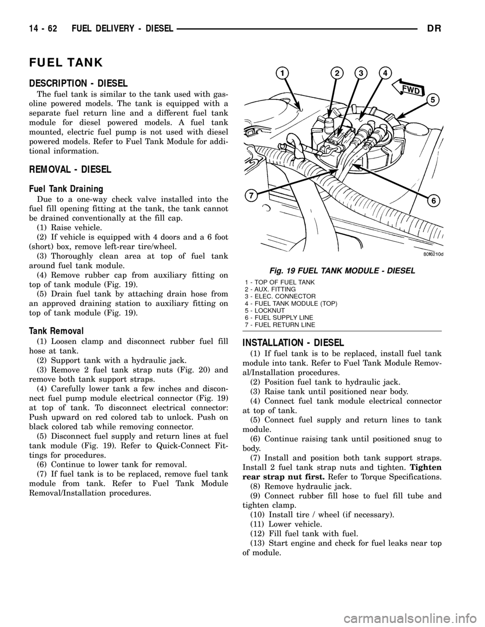
top of tank module (Fig. 19).
(5) Drain fuel tank by attaching drain hose from
an approved draining station to auxiliary fitting on
top of tank module (Fig. 19).
Tank Removal
(1) Loosen clamp and disconnect rubber fuel fill
hose at tank.
(2) Support tank with a hydraulic jack.
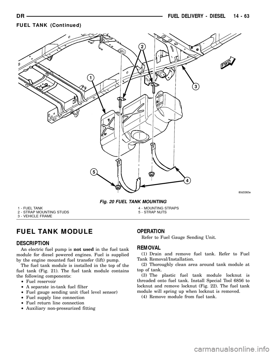
(3) Remove 2 fuel tank strap nuts (Fig. 20) and
remove both tank support straps.
(4) Carefully lower tank a few inches and discon-
nect fuel pump module electrical connector (Fig. 19)
at top of tank. To disconnect electrical connector:
Push upward on red colored tab to unlock. Push on
black colored tab while removing connector.
(5) Disconnect fuel supply and return lines at fuel
tank module (Fig. 19). Refer to Quick-Connect Fit-
tings for procedures.
(6) Continue to lower tank for removal.
(7) If fuel tank is to be replaced, remove fuel tank
module from tank. Refer to Fuel Tank Module
Removal/Installation procedures.INSTALLATION - DIESEL
(1) If fuel tank is to be replaced, install fuel tank
module into tank. Refer to Fuel Tank Module Remov-
al/Installation procedures.
(2) Position fuel tank to hydraulic jack.
(3) Raise tank until positioned near body.
(4) Connect fuel tank module electrical connector
at top of tank.
(5) Connect fuel supply and return lines to tank
module.
(6) Continue raising tank until positioned snug to
body.
(7) Install and position both tank support straps.
Install 2 fuel tank strap nuts and tighten.Tighten
rear strap nut first.Refer to Torque Specifications.
(8) Remove hydraulic jack.
(9) Connect rubber fill hose to fuel fill tube and
tighten clamp.
(10) Install tire / wheel (if necessary).
(11) Lower vehicle.
(12) Fill fuel tank with fuel.
(13) Start engine and check for fuel leaks near top
of module.
Fig. 19 FUEL TANK MODULE - DIESEL
1 - TOP OF FUEL TANK
2 - AUX. FITTING
3 - ELEC. CONNECTOR
4 - FUEL TANK MODULE (TOP)
5 - LOCKNUT
6 - FUEL SUPPLY LINE
7 - FUEL RETURN LINE
14 - 62 FUEL DELIVERY - DIESELDR
Page 1632 of 2627
FUEL TANK MODULE
DESCRIPTION
An electric fuel pump isnot usedin the fuel tank
module for diesel powered engines. Fuel is supplied
by the engine mounted fuel transfer (lift) pump.
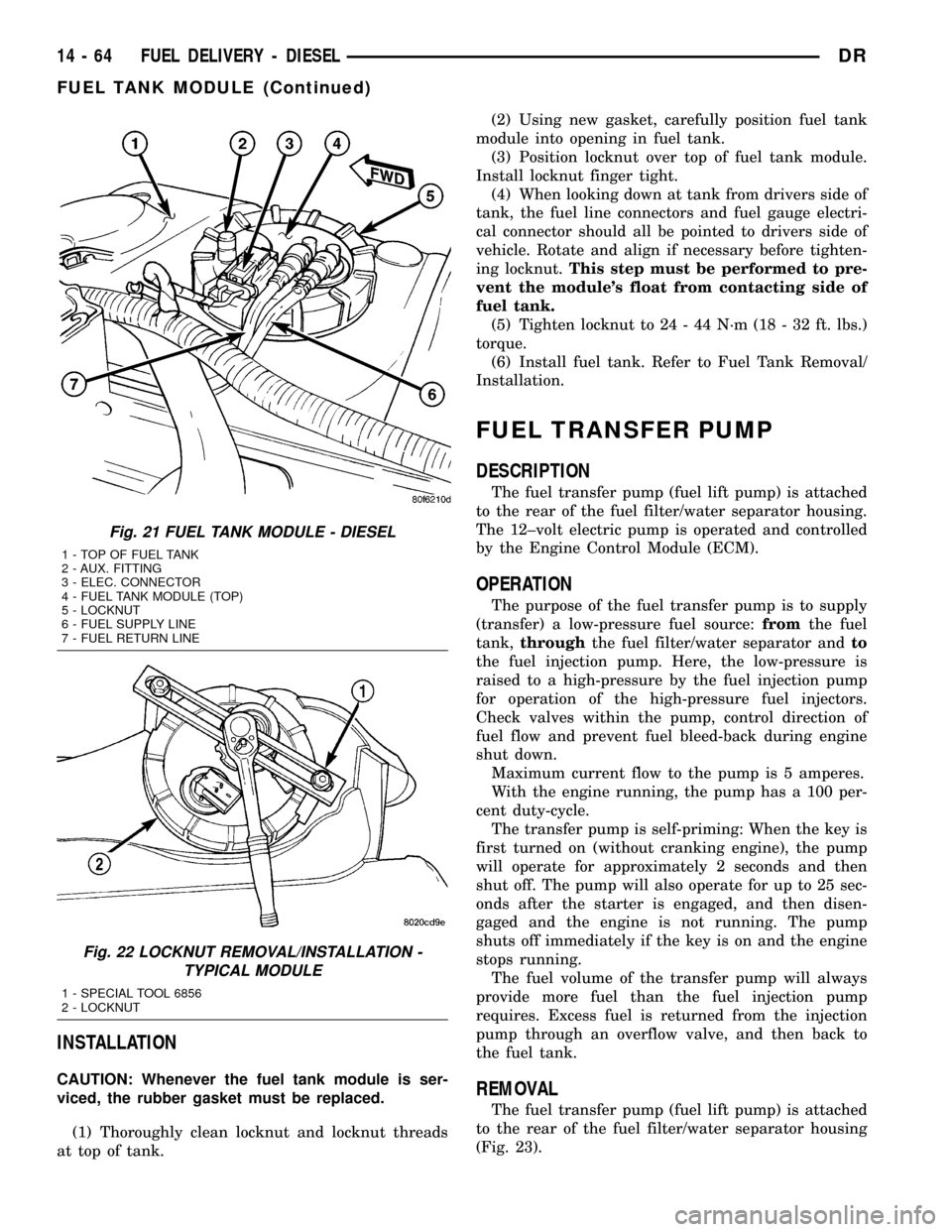
The fuel tank module is installed in the top of the
fuel tank (Fig. 21). The fuel tank module contains
the following components:
²Fuel reservoir
²A separate in-tank fuel filter
²Fuel gauge sending unit (fuel level sensor)
²Fuel supply line connection
²Fuel return line connection
²Auxiliary non-pressurized fitting
OPERATION
Refer to Fuel Gauge Sending Unit.
REMOVAL
(1) Drain and remove fuel tank. Refer to Fuel
Tank Removal/Installation.
(2) Thoroughly clean area around tank module at
top of tank.
(3) The plastic fuel tank module locknut is
threaded onto fuel tank. Install Special Tool 6856 to
locknut and remove locknut (Fig. 22). The fuel tank
module will spring up when locknut is removed.
(4) Remove module from fuel tank.
Fig. 20 FUEL TANK MOUNTING
1 - FUEL TANK
2 - STRAP MOUNTING STUDS
3 - VEHICLE FRAME4 - MOUNTING STRAPS
5 - STRAP NUTS
DRFUEL DELIVERY - DIESEL 14 - 63
FUEL TANK (Continued)
Page 1633 of 2627
INSTALLATION
CAUTION: Whenever the fuel tank module is ser-
viced, the rubber gasket must be replaced.
(1) Thoroughly clean locknut and locknut threads
at top of tank.(2) Using new gasket, carefully position fuel tank
module into opening in fuel tank.
(3) Position locknut over top of fuel tank module.
Install locknut finger tight.
(4) When looking down at tank from drivers side of
tank, the fuel line connectors and fuel gauge electri-
cal connector should all be pointed to drivers side of
vehicle. Rotate and align if necessary before tighten-
ing locknut.This step must be performed to pre-
vent the module's float from contacting side of
fuel tank.
(5) Tighten locknut to 24 - 44 N´m (18 - 32 ft. lbs.)
torque.
(6) Install fuel tank. Refer to Fuel Tank Removal/
Installation.
FUEL TRANSFER PUMP
DESCRIPTION
The fuel transfer pump (fuel lift pump) is attached
to the rear of the fuel filter/water separator housing.
The 12±volt electric pump is operated and controlled
by the Engine Control Module (ECM).
OPERATION
The purpose of the fuel transfer pump is to supply
(transfer) a low-pressure fuel source:fromthe fuel
tank,throughthe fuel filter/water separator andto
the fuel injection pump. Here, the low-pressure is
raised to a high-pressure by the fuel injection pump
for operation of the high-pressure fuel injectors.
Check valves within the pump, control direction of
fuel flow and prevent fuel bleed-back during engine
shut down.
Maximum current flow to the pump is 5 amperes.
With the engine running, the pump has a 100 per-
cent duty-cycle.
The transfer pump is self-priming: When the key is
first turned on (without cranking engine), the pump
will operate for approximately 2 seconds and then
shut off. The pump will also operate for up to 25 sec-
onds after the starter is engaged, and then disen-
gaged and the engine is not running. The pump
shuts off immediately if the key is on and the engine
stops running.
The fuel volume of the transfer pump will always
provide more fuel than the fuel injection pump
requires. Excess fuel is returned from the injection
pump through an overflow valve, and then back to
the fuel tank.
REMOVAL
The fuel transfer pump (fuel lift pump) is attached
to the rear of the fuel filter/water separator housing
(Fig. 23).
Fig. 21 FUEL TANK MODULE - DIESEL
1 - TOP OF FUEL TANK
2 - AUX. FITTING
3 - ELEC. CONNECTOR
4 - FUEL TANK MODULE (TOP)
5 - LOCKNUT
6 - FUEL SUPPLY LINE
7 - FUEL RETURN LINE
Fig. 22 LOCKNUT REMOVAL/INSTALLATION -
TYPICAL MODULE
1 - SPECIAL TOOL 6856
2 - LOCKNUT
14 - 64 FUEL DELIVERY - DIESELDR
FUEL TANK MODULE (Continued)
Page 1645 of 2627
(3) Remove valve cover. Refer to Engines for proce-
dures.
(4) Remove necessary high pressure fuel line con-
necting necessary fuel injector rail to high pressure
connector. Refer to Fuel Line Removal for procedures.
(5) A connector retainer (nut) (Fig. 15) is used on
each connector tube. Remove this nut(s) by unthread-
ing from cylinder head.
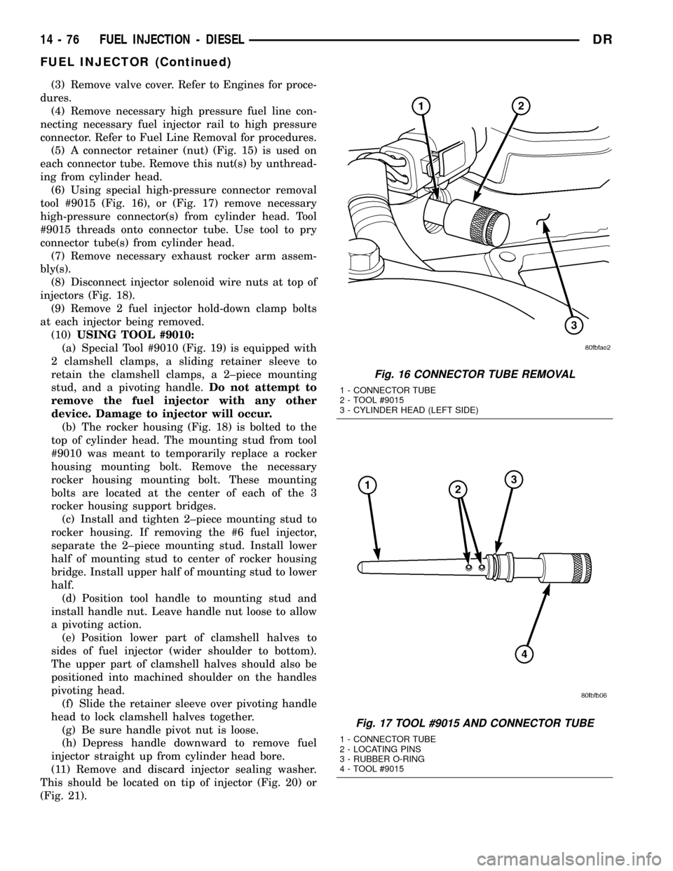
(6) Using special high-pressure connector removal
tool #9015 (Fig. 16), or (Fig. 17) remove necessary
high-pressure connector(s) from cylinder head. Tool
#9015 threads onto connector tube. Use tool to pry
connector tube(s) from cylinder head.
(7) Remove necessary exhaust rocker arm assem-
bly(s).
(8) Disconnect injector solenoid wire nuts at top of
injectors (Fig. 18).
(9) Remove 2 fuel injector hold-down clamp bolts
at each injector being removed.
(10)USING TOOL #9010:
(a) Special Tool #9010 (Fig. 19) is equipped with
2 clamshell clamps, a sliding retainer sleeve to
retain the clamshell clamps, a 2±piece mounting
stud, and a pivoting handle.Do not attempt to
remove the fuel injector with any other
device. Damage to injector will occur.
(b) The rocker housing (Fig. 18) is bolted to the
top of cylinder head. The mounting stud from tool
#9010 was meant to temporarily replace a rocker
housing mounting bolt. Remove the necessary
rocker housing mounting bolt. These mounting
bolts are located at the center of each of the 3
rocker housing support bridges.
(c) Install and tighten 2±piece mounting stud to
rocker housing. If removing the #6 fuel injector,
separate the 2±piece mounting stud. Install lower
half of mounting stud to center of rocker housing
bridge. Install upper half of mounting stud to lower
half.
(d) Position tool handle to mounting stud and
install handle nut. Leave handle nut loose to allow
a pivoting action.
(e) Position lower part of clamshell halves to
sides of fuel injector (wider shoulder to bottom).
The upper part of clamshell halves should also be
positioned into machined shoulder on the handles
pivoting head.
(f) Slide the retainer sleeve over pivoting handle
head to lock clamshell halves together.
(g) Be sure handle pivot nut is loose.
(h) Depress handle downward to remove fuel
injector straight up from cylinder head bore.
(11) Remove and discard injector sealing washer.
This should be located on tip of injector (Fig. 20) or
(Fig. 21).
Fig. 16 CONNECTOR TUBE REMOVAL
1 - CONNECTOR TUBE
2 - TOOL #9015
3 - CYLINDER HEAD (LEFT SIDE)
Fig. 17 TOOL #9015 AND CONNECTOR TUBE
1 - CONNECTOR TUBE
2 - LOCATING PINS
3 - RUBBER O-RING
4 - TOOL #9015
14 - 76 FUEL INJECTION - DIESELDR
FUEL INJECTOR (Continued)