1998 DODGE RAM 1500 wheel alignment
[x] Cancel search: wheel alignmentPage 1501 of 2627
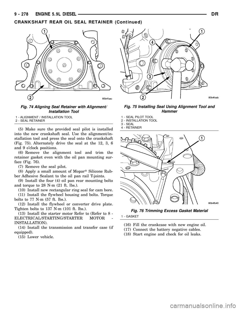
(5) Make sure the provided seal pilot is installed
into the new crankshaft seal. Use the alignment/in-
stallation tool and press the seal onto the crankshaft
(Fig. 75). Alternately drive the seal at the 12, 3, 6
and 9 o'clock positions.
(6) Remove the alignment tool and trim the
retainer gasket even with the oil pan mounting sur-
face (Fig. 76).
(7) Remove the seal pilot.
(8) Apply a small amount of MopartSilicone Rub-
ber Adhesive Sealant to the oil pan rail T-joints.
(9) Install the four (4) oil pan rear mounting bolts
and torque to 28 N´m (21 ft. lbs.).
(10) Install new rectangular ring seal for cam bore.
(11) Install the flywheel housing and bolts. Torque
bolts to 77 N´m (57 ft. lbs.).
(12) Install the flywheel or converter drive plate.
Tighten bolts to 137 N´m (101 ft. lbs.).
(13) Install the starter motor Refer to (Refer to 8 -
ELECTRICAL/STARTING/STARTER MOTOR -
INSTALLATION).
(14) Install the transmission and transfer case (if
equipped).
(15) Lower vehicle.(16) Fill the crankcase with new engine oil.
(17) Connect the battery negative cables.
(18) Start engine and check for oil leaks.
Fig. 74 Aligning Seal Retainer with Alignment/
Installation Tool
1 - ALIGNMENT / INSTALLATION TOOL
2 - SEAL RETAINER
Fig. 75 Installing Seal Using Alignment Tool and
Hammer
1 - SEAL PILOT TOOL
2 - INSTALLATION TOOL
3 - SEAL
4 - RETAINER
Fig. 76 Trimming Excess Gasket Material
1 - GASKET
9 - 278 ENGINE 5.9L DIESELDR
CRANKSHAFT REAR OIL SEAL RETAINER (Continued)
Page 1545 of 2627
FRONT AIR DAM
REMOVAL
(1) Remove the two outboard screws.
(2) Remove the three middle screws and remove
the air dam.
INSTALLATION
(1) Position the air dam onto the bumper and seat
the carrot type fasteners fully.
(2) Starting at the center screw install the three
middle screws.
(3) Install the two outboard screws.
FRONT BUMPER
REMOVAL
(1) Using a grease pencil or equivalent, mark the
position of the bumper on the frame rail tip to aid
installation.
(2) Disconnect the fog lamp electrical connector at
the left frame rail.
(3) Support the bumper with a suitable lifting
device.
(4) Remove the center bracket nuts and bolts and
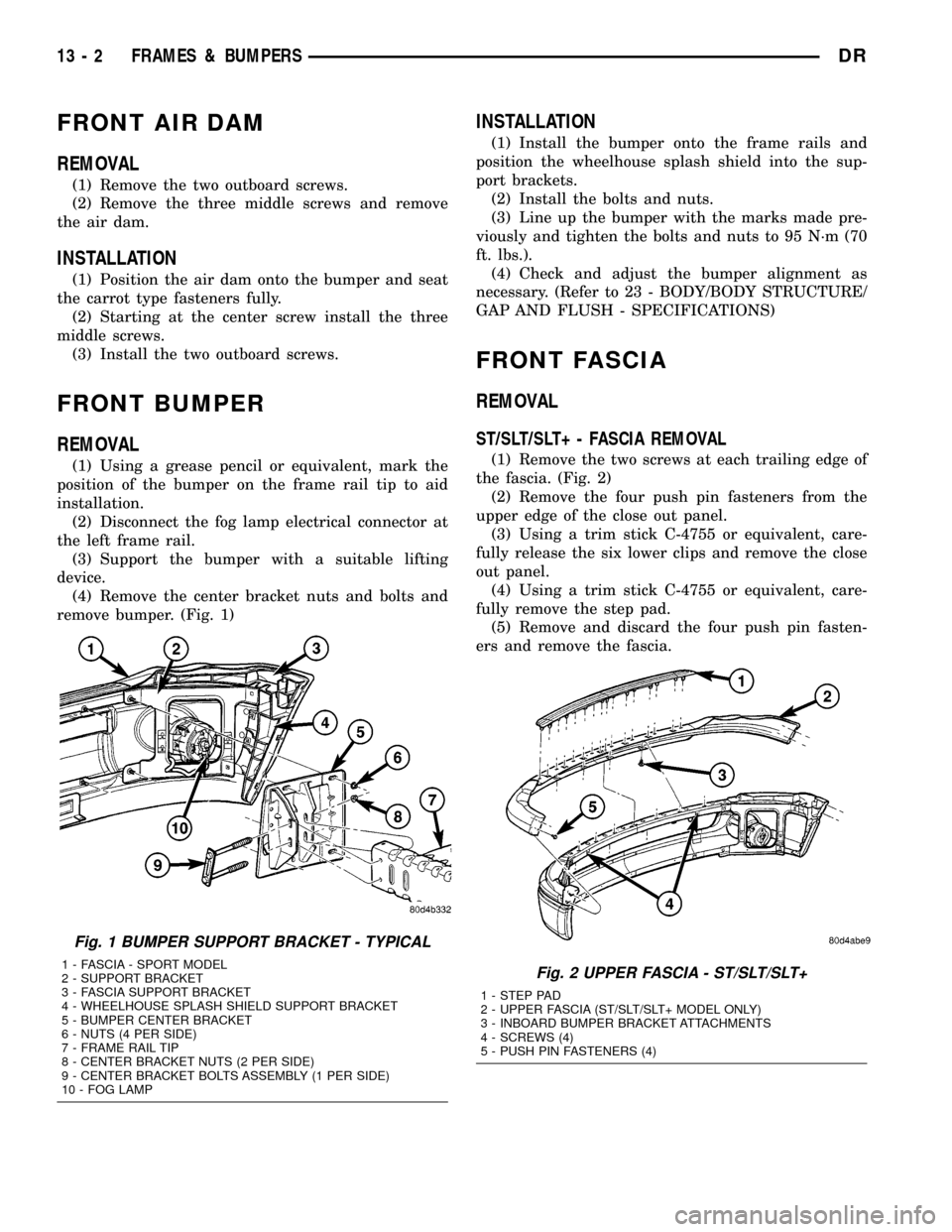
remove bumper. (Fig. 1)
INSTALLATION
(1) Install the bumper onto the frame rails and
position the wheelhouse splash shield into the sup-
port brackets.
(2) Install the bolts and nuts.
(3) Line up the bumper with the marks made pre-
viously and tighten the bolts and nuts to 95 N´m (70
ft. lbs.).
(4) Check and adjust the bumper alignment as
necessary. (Refer to 23 - BODY/BODY STRUCTURE/
GAP AND FLUSH - SPECIFICATIONS)
FRONT FASCIA
REMOVAL
ST/SLT/SLT+ - FASCIA REMOVAL
(1) Remove the two screws at each trailing edge of
the fascia. (Fig. 2)
(2) Remove the four push pin fasteners from the
upper edge of the close out panel.
(3) Using a trim stick C-4755 or equivalent, care-
fully release the six lower clips and remove the close
out panel.
(4) Using a trim stick C-4755 or equivalent, care-
fully remove the step pad.
(5) Remove and discard the four push pin fasten-
ers and remove the fascia.
Fig. 1 BUMPER SUPPORT BRACKET - TYPICAL
1 - FASCIA - SPORT MODEL
2 - SUPPORT BRACKET
3 - FASCIA SUPPORT BRACKET
4 - WHEELHOUSE SPLASH SHIELD SUPPORT BRACKET
5 - BUMPER CENTER BRACKET
6 - NUTS (4 PER SIDE)
7 - FRAME RAIL TIP
8 - CENTER BRACKET NUTS (2 PER SIDE)
9 - CENTER BRACKET BOLTS ASSEMBLY (1 PER SIDE)
10 - FOG LAMPFig. 2 UPPER FASCIA - ST/SLT/SLT+
1 - STEP PAD
2 - UPPER FASCIA (ST/SLT/SLT+ MODEL ONLY)
3 - INBOARD BUMPER BRACKET ATTACHMENTS
4 - SCREWS (4)
5 - PUSH PIN FASTENERS (4)
13 - 2 FRAMES & BUMPERSDR
Page 1552 of 2627
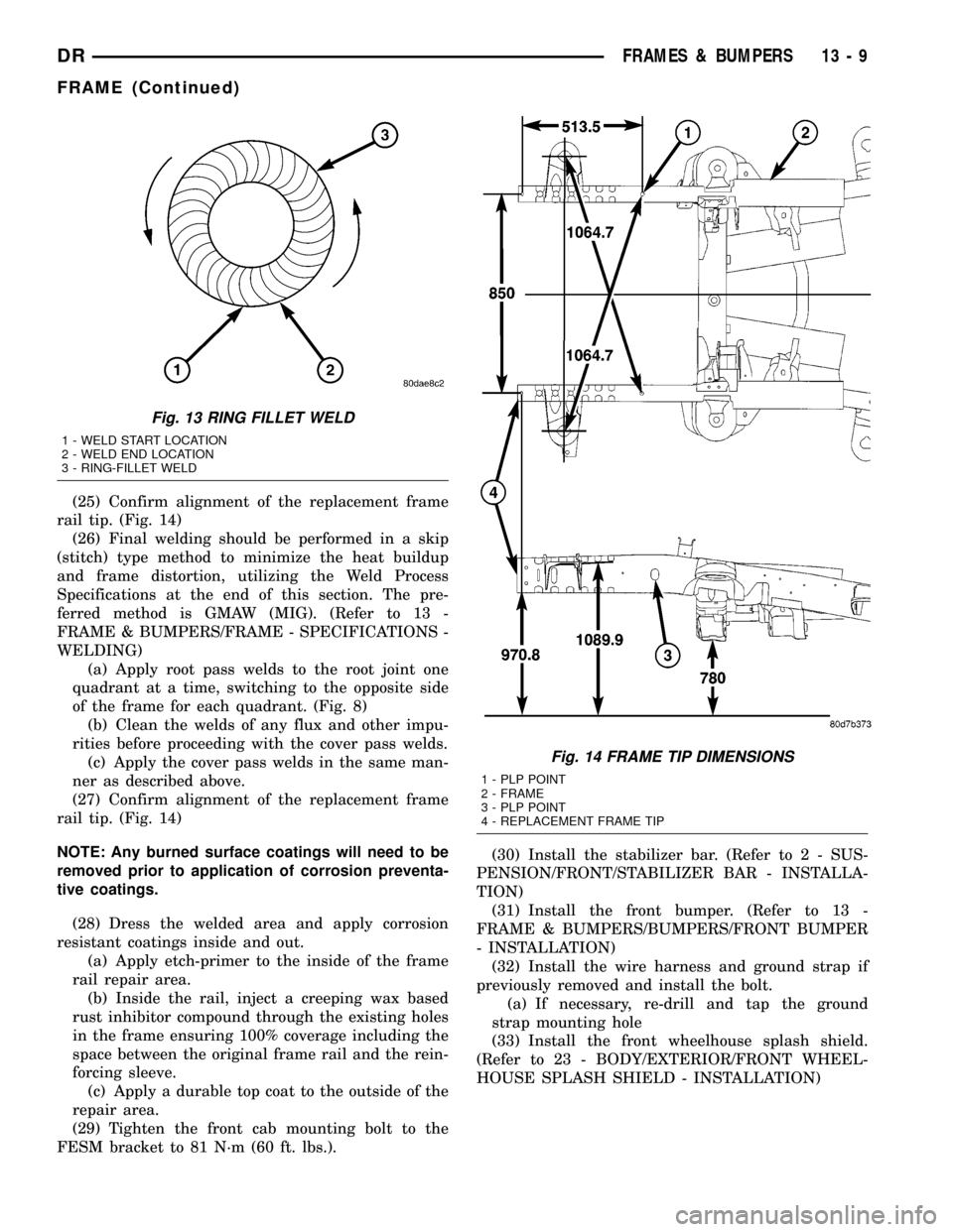
(25) Confirm alignment of the replacement frame
rail tip. (Fig. 14)
(26) Final welding should be performed in a skip
(stitch) type method to minimize the heat buildup
and frame distortion, utilizing the Weld Process
Specifications at the end of this section. The pre-
ferred method is GMAW (MIG). (Refer to 13 -
FRAME & BUMPERS/FRAME - SPECIFICATIONS -
WELDING)
(a) Apply root pass welds to the root joint one
quadrant at a time, switching to the opposite side
of the frame for each quadrant. (Fig. 8)
(b) Clean the welds of any flux and other impu-
rities before proceeding with the cover pass welds.
(c) Apply the cover pass welds in the same man-
ner as described above.
(27) Confirm alignment of the replacement frame
rail tip. (Fig. 14)
NOTE: Any burned surface coatings will need to be
removed prior to application of corrosion preventa-
tive coatings.
(28) Dress the welded area and apply corrosion
resistant coatings inside and out.
(a) Apply etch-primer to the inside of the frame
rail repair area.
(b) Inside the rail, inject a creeping wax based
rust inhibitor compound through the existing holes
in the frame ensuring 100% coverage including the
space between the original frame rail and the rein-
forcing sleeve.
(c) Apply a durable top coat to the outside of the
repair area.
(29) Tighten the front cab mounting bolt to the
FESM bracket to 81 N´m (60 ft. lbs.).(30) Install the stabilizer bar. (Refer to 2 - SUS-
PENSION/FRONT/STABILIZER BAR - INSTALLA-
TION)
(31) Install the front bumper. (Refer to 13 -
FRAME & BUMPERS/BUMPERS/FRONT BUMPER
- INSTALLATION)
(32) Install the wire harness and ground strap if
previously removed and install the bolt.
(a) If necessary, re-drill and tap the ground
strap mounting hole
(33) Install the front wheelhouse splash shield.
(Refer to 23 - BODY/EXTERIOR/FRONT WHEEL-
HOUSE SPLASH SHIELD - INSTALLATION)
Fig. 13 RING FILLET WELD
1 - WELD START LOCATION
2 - WELD END LOCATION
3 - RING-FILLET WELD
Fig. 14 FRAME TIP DIMENSIONS
1 - PLP POINT
2 - FRAME
3 - PLP POINT
4 - REPLACEMENT FRAME TIP
DRFRAMES & BUMPERS 13 - 9
FRAME (Continued)
Page 1658 of 2627
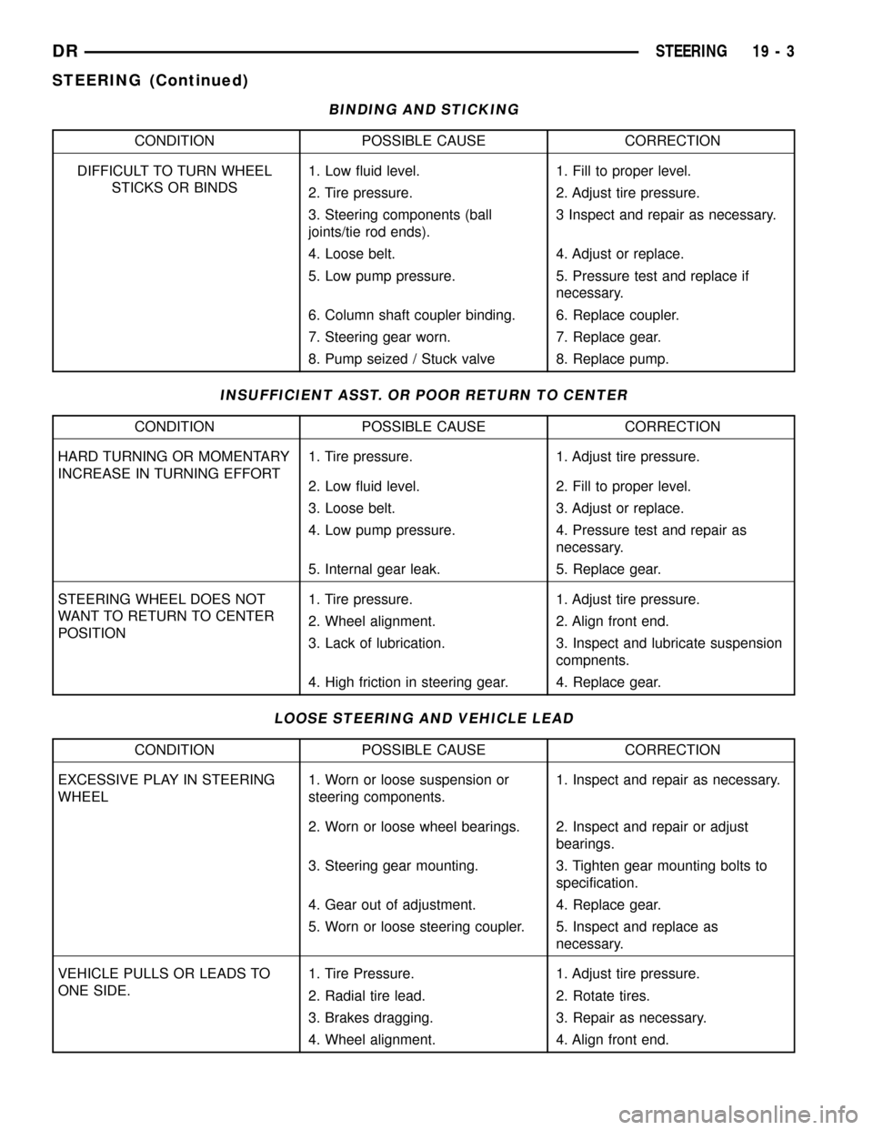
BINDING AND STICKING
CONDITION POSSIBLE CAUSE CORRECTION
DIFFICULT TO TURN WHEEL
STICKS OR BINDS1. Low fluid level. 1. Fill to proper level.
2. Tire pressure. 2. Adjust tire pressure.
3. Steering components (ball
joints/tie rod ends).3 Inspect and repair as necessary.
4. Loose belt. 4. Adjust or replace.
5. Low pump pressure. 5. Pressure test and replace if
necessary.
6. Column shaft coupler binding. 6. Replace coupler.
7. Steering gear worn. 7. Replace gear.
8. Pump seized / Stuck valve 8. Replace pump.
INSUFFICIENT ASST. OR POOR RETURN TO CENTER
CONDITION POSSIBLE CAUSE CORRECTION
HARD TURNING OR MOMENTARY
INCREASE IN TURNING EFFORT1. Tire pressure. 1. Adjust tire pressure.
2. Low fluid level. 2. Fill to proper level.
3. Loose belt. 3. Adjust or replace.
4. Low pump pressure. 4. Pressure test and repair as
necessary.
5. Internal gear leak. 5. Replace gear.
STEERING WHEEL DOES NOT
WANT TO RETURN TO CENTER
POSITION1. Tire pressure. 1. Adjust tire pressure.
2. Wheel alignment. 2. Align front end.
3. Lack of lubrication. 3. Inspect and lubricate suspension
compnents.
4. High friction in steering gear. 4. Replace gear.
LOOSE STEERING AND VEHICLE LEAD
CONDITION POSSIBLE CAUSE CORRECTION
EXCESSIVE PLAY IN STEERING
WHEEL1. Worn or loose suspension or
steering components.1. Inspect and repair as necessary.
2. Worn or loose wheel bearings. 2. Inspect and repair or adjust
bearings.
3. Steering gear mounting. 3. Tighten gear mounting bolts to
specification.
4. Gear out of adjustment. 4. Replace gear.
5. Worn or loose steering coupler. 5. Inspect and replace as
necessary.
VEHICLE PULLS OR LEADS TO
ONE SIDE.1. Tire Pressure. 1. Adjust tire pressure.
2. Radial tire lead. 2. Rotate tires.
3. Brakes dragging. 3. Repair as necessary.
4. Wheel alignment. 4. Align front end.
DRSTEERING 19 - 3
STEERING (Continued)
Page 1673 of 2627
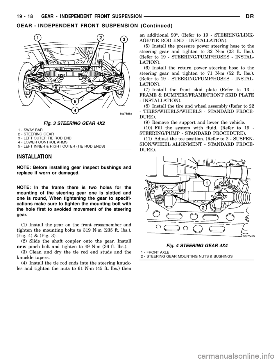
INSTALLATION
NOTE: Before installing gear inspect bushings and
replace if worn or damaged.
NOTE: In the frame there is two holes for the
mounting of the steering gear one is slotted and
one is round, When tightening the gear to specifi-
cations make sure to tighten the mounting bolt with
the hole first to avoided movement of the steering
gear.
(1) Install the gear on the front crossmember and
tighten the mounting bolts to 319 N´m (235 ft. lbs.).
(Fig. 4) & (Fig. 3).
(2) Slide the shaft coupler onto the gear. Install
newpinch bolt and tighten to 49 N´m (36 ft. lbs.).
(3) Clean and dry the tie rod end studs and the
knuckle tapers.
(4) Install the tie rod ends into the steering knuck-
les and tighten the nuts to 61 N´m (45 ft. lbs.) thenan additional 90É. (Refer to 19 - STEERING/LINK-
AGE/TIE ROD END - INSTALLATION).
(5) Install the pressure power steering hose to the
steering gear and tighten to 32 N´m (23 ft. lbs.).
(Refer to 19 - STEERING/PUMP/HOSES - INSTAL-
LATION).
(6) Install the return power steering hose to the
steering gear and tighten to 71 N´m (52 ft. lbs.).
(Refer to 19 - STEERING/PUMP/HOSES - INSTAL-
LATION).
(7) Install the front skid plate (Refer to 13 -
FRAME & BUMPERS/FRAME/FRONT SKID PLATE
- INSTALLATION).
(8) Install the tire and wheel assembly (Refer to 22
- TIRES/WHEELS/WHEELS - STANDARD PROCE-
DURE).
(9) Remove the support and lower the vehicle.
(10) Fill the system with fluid, (Refer to 19 -
STEERING/PUMP - STANDARD PROCEDURE).
(11) Adjust the toe position. (Refer to 2 - SUSPEN-
SION/WHEEL ALIGNMENT - STANDARD PROCE-
DURE).
Fig. 3 STEERING GEAR 4X2
1-SWAYBAR
2 - STEERING GEAR
3 - LEFT OUTER TIE ROD END
4 - LOWER CONTROL ARMS
5 - LEFT INNER & RIGHT OUTER (TIE ROD ENDS)
Fig. 4 STEERING GEAR 4X4
1 - FRONT AXLE
2 - STEERING GEAR MOUNTING NUTS & BUSHINGS
19 - 18 GEAR - INDEPENDENT FRONT SUSPENSIONDR
GEAR - INDEPENDENT FRONT SUSPENSION (Continued)
Page 1674 of 2627
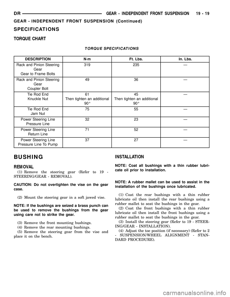
SPECIFICATIONS
TORQUE CHART
TORQUE SPECIFICATIONS
DESCRIPTION N´m Ft. Lbs. In. Lbs.
Rack and Pinion Steering
Gear
Gear to Frame Bolts319 235 Ð
Rack and Pinion Steering
Gear
Coupler Bolt49 36 Ð
Tie Rod End
Knuckle Nut61
Then tighten an additional
90É45
Then tighten an additional
90ÉÐ
Tie Rod End
Jam Nut75 55 Ð
Power Steering Line
Pressure Line32 23 Ð
Power Steering Line
Return Line71 52 Ð
Power Steering Line
Pressure Line To Pump37 27 Ð
BUSHING
REMOVAL
(1) Remove the steering gear (Refer to 19 -
STEERING/GEAR - REMOVAL).
CAUTION: Do not overtighten the vise on the gear
case.
(2) Mount the steering gear in a soft jawed vise.
NOTE: If the bushings are seized a brass punch can
be used to remove the bushings from the gear
using care not to strike the gear.
(3) Remove the front mounting bushings.
(4) Remove the rear mounting bushings.
(5) Remove the steering gear from the vise and
place it on the bench.
INSTALLATION
NOTE: Coat all bushings with a thin rubber lubri-
cate oil prior to installation.
NOTE: A rubber mallet can be used to assist in the
installation of the bushings once lubricated.
(1) Coat the rear bushings with a thin rubber
lubricate oil then install the rear bushings using a
rubber mallet to seat the bushings in the gear.
(2) Coat the front bushings with a thin rubber
lubricate oil then install the front bushings using a
rubber mallet to seat the bushings in the gear.
(3) Install the steering gear (Refer to 19 - STEER-
ING/GEAR - INSTALLATION).
(4) Adjust the toe position (if necessary) (Refer to 2
- SUSPENSION/WHEEL ALIGNMENT - STAN-
DARD PROCEDURE).
DRGEAR - INDEPENDENT FRONT SUSPENSION 19 - 19
GEAR - INDEPENDENT FRONT SUSPENSION (Continued)
Page 1676 of 2627
(4) Disconnect and cap the fluid hoses from steer-
ing gear (Refer to 19 - STEERING/PUMP/HOSES -
REMOVAL).
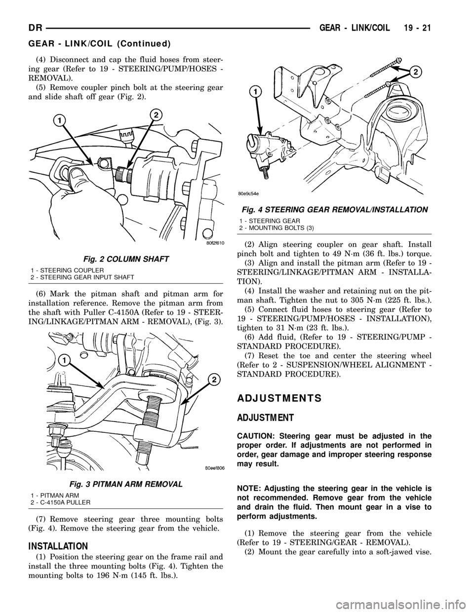
(5) Remove coupler pinch bolt at the steering gear
and slide shaft off gear (Fig. 2).
(6) Mark the pitman shaft and pitman arm for
installation reference. Remove the pitman arm from
the shaft with Puller C-4150A (Refer to 19 - STEER-
ING/LINKAGE/PITMAN ARM - REMOVAL), (Fig. 3).
(7) Remove steering gear three mounting bolts
(Fig. 4). Remove the steering gear from the vehicle.
INSTALLATION
(1) Position the steering gear on the frame rail and
install the three mounting bolts (Fig. 4). Tighten the
mounting bolts to 196 N´m (145 ft. lbs.).(2) Align steering coupler on gear shaft. Install
pinch bolt and tighten to 49 N´m (36 ft. lbs.) torque.
(3) Align and install the pitman arm (Refer to 19 -
STEERING/LINKAGE/PITMAN ARM - INSTALLA-
TION).
(4) Install the washer and retaining nut on the pit-
man shaft. Tighten the nut to 305 N´m (225 ft. lbs.).
(5) Connect fluid hoses to steering gear (Refer to
19 - STEERING/PUMP/HOSES - INSTALLATION),
tighten to 31 N´m (23 ft. lbs.).
(6) Add fluid, (Refer to 19 - STEERING/PUMP -
STANDARD PROCEDURE).
(7) Reset the toe and center the steering wheel
(Refer to 2 - SUSPENSION/WHEEL ALIGNMENT -
STANDARD PROCEDURE).
ADJUSTMENTS
ADJUSTMENT
CAUTION: Steering gear must be adjusted in the
proper order. If adjustments are not performed in
order, gear damage and improper steering response
may result.
NOTE: Adjusting the steering gear in the vehicle is
not recommended. Remove gear from the vehicle
and drain the fluid. Then mount gear in a vise to
perform adjustments.
(1) Remove the steering gear from the vehicle
(Refer to 19 - STEERING/GEAR - REMOVAL).
(2) Mount the gear carefully into a soft-jawed vise.
Fig. 2 COLUMN SHAFT
1 - STEERING COUPLER
2 - STEERING GEAR INPUT SHAFT
Fig. 3 PITMAN ARM REMOVAL
1 - PITMAN ARM
2 - C-4150A PULLER
Fig. 4 STEERING GEAR REMOVAL/INSTALLATION
1 - STEERING GEAR
2 - MOUNTING BOLTS (3)
DRGEAR - LINK/COIL 19 - 21
GEAR - LINK/COIL (Continued)
Page 1682 of 2627
(11) Install the pitman arm (Refer to 19 - STEER-
ING/LINKAGE/PITMAN ARM - INSTALLATION).
(12) Perform a wheel alignment (Refer to 2 - SUS-
PENSION/WHEEL ALIGNMENT - STANDARD
PROCEDURE).
STEERING GEAR INPUT
SHAFT SEAL
REMOVAL
(1) Remove the steering gear from the vehicle
(Refer to 19 - STEERING/GEAR - REMOVAL).
CAUTION: Do not overtighten the vise on the gear
case. This may affect the adjustment
(2) Mount the steering gear upside down over a
drain pan in a soft jawed vise.
(3) Place a drain pan under the gear and rotate
the input shaft back and forth several times lock-to-
lock to discharge the fluid from the steering gear
(4) Drain all the remaining fluid from the gear.
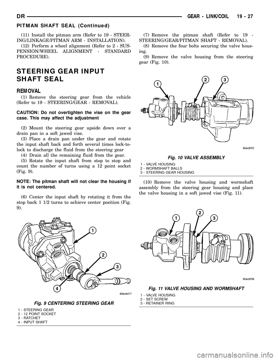
(5) Rotate the input shaft from stop to stop and
count the number of turns using a 12 point socket
(Fig. 9).
NOTE: The pitman shaft will not clear the housing if
it is not centered.
(6) Center the input shaft by rotating it from the
stop back 1 1/2 turns to achieve center position (Fig.
9).(7) Remove the pitman shaft (Refer to 19 -
STEERING/GEAR/PITMAN SHAFT - REMOVAL).
(8) Remove the four bolts securing the valve hous-
ing.
(9) Remove the valve housing from the steering
gear (Fig. 10).
(10) Remove the valve housing and wormshaft
assembly from the steering gear housing and place
the valve housing in a soft jawed vise (Fig. 11).
Fig. 9 CENTERING STEERING GEAR
1 - STEERING GEAR
2 - 12 POINT SOCKET
3 - RATCHET
4 - INPUT SHAFT
Fig. 10 VALVE ASSEMBLY
1 - VALVE HOUSING
2 - WORMSHAFT BALLS
3 - STEERING GEAR HOUSING
Fig. 11 VALVE HOUSING AND WORMSHAFT
1 - VALVE HOUSING
2 - SET SCREW
3 - RETAINER RING
DRGEAR - LINK/COIL 19 - 27
PITMAN SHAFT SEAL (Continued)