1998 DODGE RAM 1500 fuel cap
[x] Cancel search: fuel capPage 1624 of 2627
INSTALLATION
CAUTION: Cleanliness cannot be overemphasized
when handling or replacing diesel fuel system com-
ponents. This especially includes the fuel injectors,
high-pressure fuel lines and fuel injection pump.
Very tight tolerances are used with these parts. Dirt
contamination could cause rapid part wear and pos-
sible plugging of fuel injector nozzle tip holes. This
in turn could lead to possible engine misfire.
Always wash/clean any fuel system component
thoroughly before disassembly and then air dry.
Cap or cover any open part after disassembly.
Before assembly, examine each part for dirt, grease
or other contaminants and clean if necessary. When
installing new parts, lubricate them with clean
engine oil or clean diesel fuel only.
(1) Inspect pump mounting surfaces at pump and
mounting flange for nicks, cuts or damage. Inspect
o-ring surfaces for nicks, cuts or damage.
(2) Clean injection pump mounting flange at gear
housing. Also clean front of injection pump.
(3) Install new rubber o-ring into machined groove
(Fig. 12) at pump mounting area.
(4) Apply clean engine oilto injection pump
o-ring only.
The machined tapers on both injection pump
shaft and injection pump gear must be abso-
lutely dry, clean and free of any dirt or oil film.
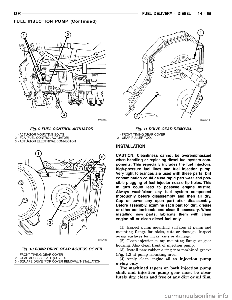
Fig. 9 FUEL CONTROL ACTUATOR
1 - ACTUATOR MOUNTING BOLTS
2 - FCA (FUEL CONTROL ACTUATOR)
3 - ACTUATOR ELECTRICAL CONNECTOR
Fig. 10 PUMP DRIVE GEAR ACCESS COVER
1 - FRONT TIMING GEAR COVER
2 - GEAR ACCESS PLATE (COVER)
3 - SQUARE DRIVE (FOR COVER REMOVAL/INSTALLATION)
Fig. 11 DRIVE GEAR REMOVAL
1 - FRONT TIMING GEAR COVER
2 - GEAR PULLER TOOL
DRFUEL DELIVERY - DIESEL 14 - 55
FUEL INJECTION PUMP (Continued)
Page 1627 of 2627
WARNING: USE EXTREME CAUTION WHEN
INSPECTING FOR HIGH-PRESSURE FUEL LEAKS.
INSPECT FOR HIGH-PRESSURE FUEL LEAKS WITH
A SHEET OF CARDBOARD. HIGH FUEL INJECTION
PRESSURE CAN CAUSE PERSONAL INJURY IF
CONTACT IS MADE WITH THE SKIN.
DIAGNOSIS AND TESTING - HIGH-PRESSURE
FUEL LINE LEAKS
High-pressure fuel line leaks can cause starting
problems and poor engine performance.
WARNING: DUE TO EXTREME FUEL PRESSURES
OF UP TO 160,000 kPa (23,206 PSI), USE EXTREME
CAUTION WHEN INSPECTING FOR HIGH-PRES-
SURE FUEL LEAKS. DO NOT GET YOUR HAND OR
A FINGER NEAR A SUSPECTED LEAK. INSPECT
FOR HIGH-PRESSURE FUEL LEAKS WITH A SHEET
OF CARDBOARD. HIGH FUEL INJECTION PRES-
SURE CAN CAUSE PERSONAL INJURY IF CON-
TACT IS MADE WITH THE SKIN.
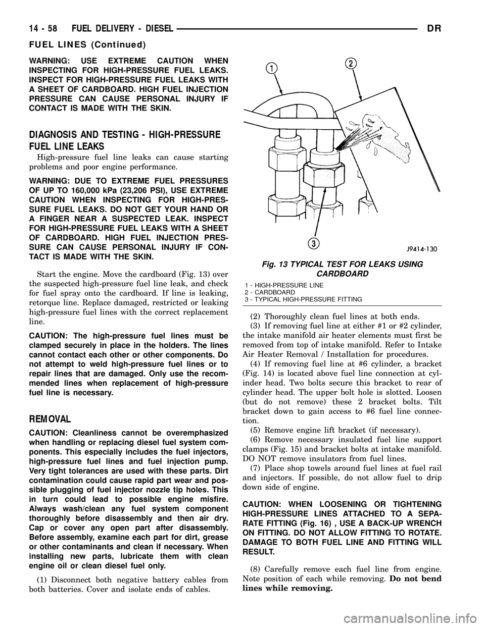
Start the engine. Move the cardboard (Fig. 13) over
the suspected high-pressure fuel line leak, and check
for fuel spray onto the cardboard. If line is leaking,
retorque line. Replace damaged, restricted or leaking
high-pressure fuel lines with the correct replacement
line.
CAUTION: The high-pressure fuel lines must be
clamped securely in place in the holders. The lines
cannot contact each other or other components. Do
not attempt to weld high-pressure fuel lines or to
repair lines that are damaged. Only use the recom-
mended lines when replacement of high-pressure
fuel line is necessary.
REMOVAL
CAUTION: Cleanliness cannot be overemphasized
when handling or replacing diesel fuel system com-
ponents. This especially includes the fuel injectors,
high-pressure fuel lines and fuel injection pump.
Very tight tolerances are used with these parts. Dirt
contamination could cause rapid part wear and pos-
sible plugging of fuel injector nozzle tip holes. This
in turn could lead to possible engine misfire.
Always wash/clean any fuel system component
thoroughly before disassembly and then air dry.
Cap or cover any open part after disassembly.
Before assembly, examine each part for dirt, grease
or other contaminants and clean if necessary. When
installing new parts, lubricate them with clean
engine oil or clean diesel fuel only.
(1) Disconnect both negative battery cables from
both batteries. Cover and isolate ends of cables.(2) Thoroughly clean fuel lines at both ends.
(3) If removing fuel line at either #1 or #2 cylinder,
the intake manifold air heater elements must first be
removed from top of intake manifold. Refer to Intake
Air Heater Removal / Installation for procedures.
(4) If removing fuel line at #6 cylinder, a bracket
(Fig. 14) is located above fuel line connection at cyl-
inder head. Two bolts secure this bracket to rear of
cylinder head. The upper bolt hole is slotted. Loosen
(but do not remove) these 2 bracket bolts. Tilt
bracket down to gain access to #6 fuel line connec-
tion.
(5) Remove engine lift bracket (if necessary).
(6) Remove necessary insulated fuel line support
clamps (Fig. 15) and bracket bolts at intake manifold.
DO NOT remove insulators from fuel lines.
(7) Place shop towels around fuel lines at fuel rail
and injectors. If possible, do not allow fuel to drip
down side of engine.
CAUTION: WHEN LOOSENING OR TIGHTENING
HIGH-PRESSURE LINES ATTACHED TO A SEPA-
RATE FITTING (Fig. 16) , USE A BACK-UP WRENCH
ON FITTING. DO NOT ALLOW FITTING TO ROTATE.
DAMAGE TO BOTH FUEL LINE AND FITTING WILL
RESULT.
(8) Carefully remove each fuel line from engine.
Note position of each while removing.Do not bend
lines while removing.
Fig. 13 TYPICAL TEST FOR LEAKS USING
CARDBOARD
1 - HIGH-PRESSURE LINE
2 - CARDBOARD
3 - TYPICAL HIGH-PRESSURE FITTING
14 - 58 FUEL DELIVERY - DIESELDR
FUEL LINES (Continued)
Page 1630 of 2627
INSTALLATION
(1) Inspect fuel pressure sensor sealing surface.
(2) Lubricate sensor threads with clean diesel fuel.
(3) Install sensor into fuel rail.
(4) To prevent leaks, sensormustbe tightened to
prescribed torque. Refer to Torque Specifications.
(5) Connect electrical connector to sensor.
(6) Start engine and check for fuel leaks.
FUEL PRESSURE LIMITING
VA LV E
DESCRIPTION
The fuel pressure limiting valve is located on the
top of the fuel rail.
OPERATION
Fuel pressure at the fuel rail is monitored by the
fuel rail pressure sensor. If fuel pressure becomes
excessive, the pressure limiting valve opens and
vents excess pressure into the fuel drain circuit.
REMOVAL
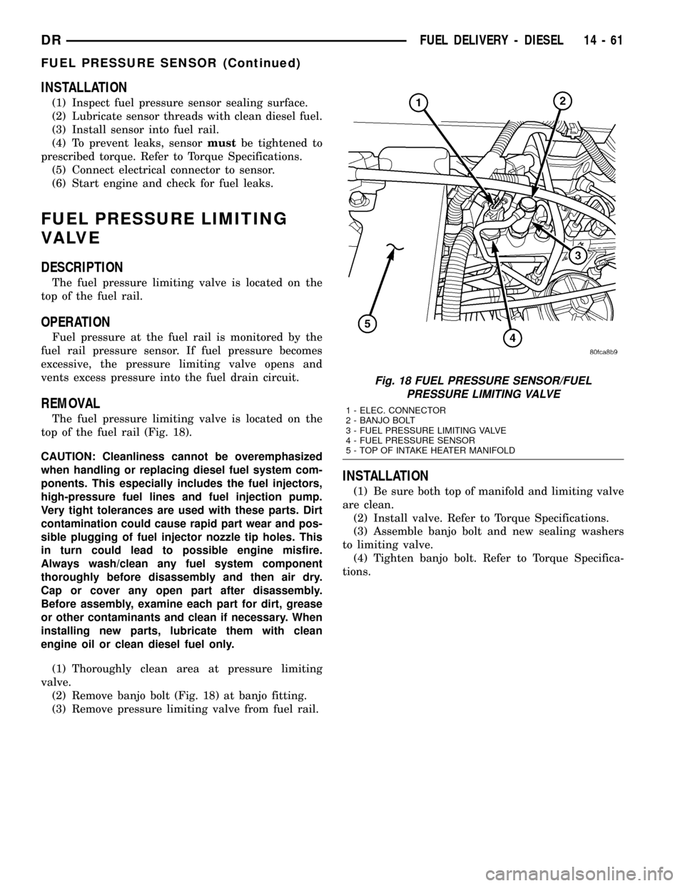
The fuel pressure limiting valve is located on the
top of the fuel rail (Fig. 18).
CAUTION: Cleanliness cannot be overemphasized
when handling or replacing diesel fuel system com-
ponents. This especially includes the fuel injectors,
high-pressure fuel lines and fuel injection pump.
Very tight tolerances are used with these parts. Dirt
contamination could cause rapid part wear and pos-
sible plugging of fuel injector nozzle tip holes. This
in turn could lead to possible engine misfire.
Always wash/clean any fuel system component
thoroughly before disassembly and then air dry.
Cap or cover any open part after disassembly.
Before assembly, examine each part for dirt, grease
or other contaminants and clean if necessary. When
installing new parts, lubricate them with clean
engine oil or clean diesel fuel only.
(1) Thoroughly clean area at pressure limiting
valve.
(2) Remove banjo bolt (Fig. 18) at banjo fitting.
(3) Remove pressure limiting valve from fuel rail.
INSTALLATION
(1) Be sure both top of manifold and limiting valve
are clean.
(2) Install valve. Refer to Torque Specifications.
(3) Assemble banjo bolt and new sealing washers
to limiting valve.
(4) Tighten banjo bolt. Refer to Torque Specifica-
tions.
Fig. 18 FUEL PRESSURE SENSOR/FUEL
PRESSURE LIMITING VALVE
1 - ELEC. CONNECTOR
2 - BANJO BOLT
3 - FUEL PRESSURE LIMITING VALVE
4 - FUEL PRESSURE SENSOR
5 - TOP OF INTAKE HEATER MANIFOLD
DRFUEL DELIVERY - DIESEL 14 - 61
FUEL PRESSURE SENSOR (Continued)
Page 1631 of 2627
FUEL TANK
DESCRIPTION - DIESEL
The fuel tank is similar to the tank used with gas-
oline powered models. The tank is equipped with a
separate fuel return line and a different fuel tank
module for diesel powered models. A fuel tank
mounted, electric fuel pump is not used with diesel
powered models. Refer to Fuel Tank Module for addi-
tional information.
REMOVAL - DIESEL
Fuel Tank Draining
Due to a one-way check valve installed into the
fuel fill opening fitting at the tank, the tank cannot
be drained conventionally at the fill cap.
(1) Raise vehicle.
(2) If vehicle is equipped with 4 doors and a 6 foot
(short) box, remove left-rear tire/wheel.
(3) Thoroughly clean area at top of fuel tank
around fuel tank module.
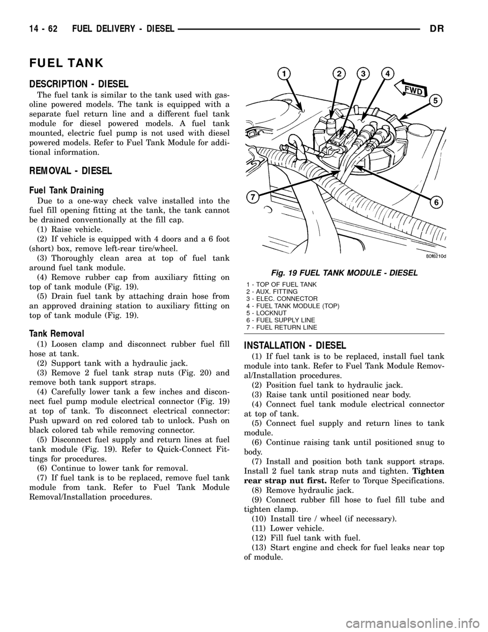
(4) Remove rubber cap from auxiliary fitting on
top of tank module (Fig. 19).
(5) Drain fuel tank by attaching drain hose from
an approved draining station to auxiliary fitting on
top of tank module (Fig. 19).
Tank Removal
(1) Loosen clamp and disconnect rubber fuel fill
hose at tank.
(2) Support tank with a hydraulic jack.
(3) Remove 2 fuel tank strap nuts (Fig. 20) and
remove both tank support straps.
(4) Carefully lower tank a few inches and discon-
nect fuel pump module electrical connector (Fig. 19)
at top of tank. To disconnect electrical connector:
Push upward on red colored tab to unlock. Push on
black colored tab while removing connector.
(5) Disconnect fuel supply and return lines at fuel
tank module (Fig. 19). Refer to Quick-Connect Fit-
tings for procedures.
(6) Continue to lower tank for removal.
(7) If fuel tank is to be replaced, remove fuel tank
module from tank. Refer to Fuel Tank Module
Removal/Installation procedures.INSTALLATION - DIESEL
(1) If fuel tank is to be replaced, install fuel tank
module into tank. Refer to Fuel Tank Module Remov-
al/Installation procedures.
(2) Position fuel tank to hydraulic jack.
(3) Raise tank until positioned near body.
(4) Connect fuel tank module electrical connector
at top of tank.
(5) Connect fuel supply and return lines to tank
module.
(6) Continue raising tank until positioned snug to
body.
(7) Install and position both tank support straps.
Install 2 fuel tank strap nuts and tighten.Tighten
rear strap nut first.Refer to Torque Specifications.
(8) Remove hydraulic jack.
(9) Connect rubber fill hose to fuel fill tube and
tighten clamp.
(10) Install tire / wheel (if necessary).
(11) Lower vehicle.
(12) Fill fuel tank with fuel.
(13) Start engine and check for fuel leaks near top
of module.
Fig. 19 FUEL TANK MODULE - DIESEL
1 - TOP OF FUEL TANK
2 - AUX. FITTING
3 - ELEC. CONNECTOR
4 - FUEL TANK MODULE (TOP)
5 - LOCKNUT
6 - FUEL SUPPLY LINE
7 - FUEL RETURN LINE
14 - 62 FUEL DELIVERY - DIESELDR
Page 1644 of 2627
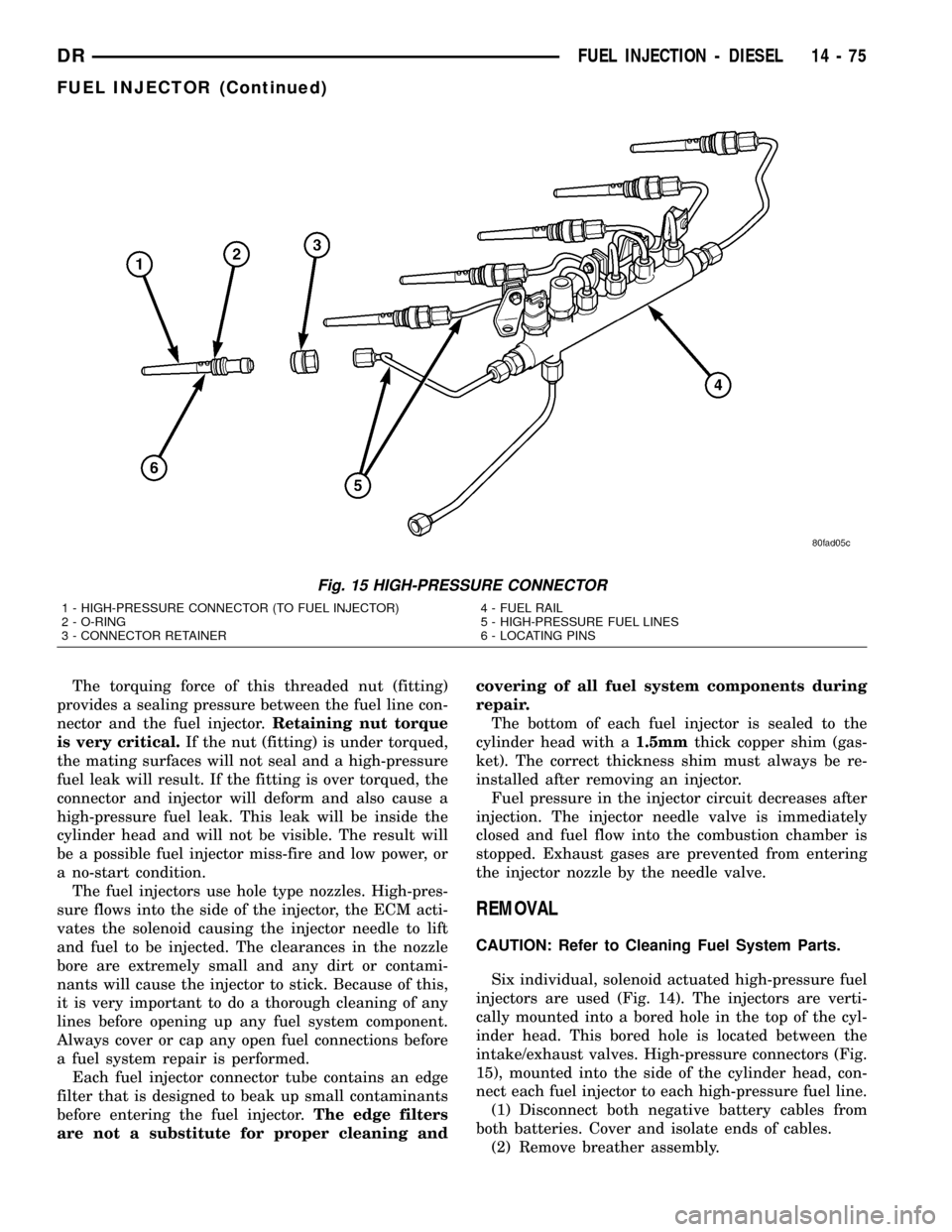
The torquing force of this threaded nut (fitting)
provides a sealing pressure between the fuel line con-
nector and the fuel injector.Retaining nut torque
is very critical.If the nut (fitting) is under torqued,
the mating surfaces will not seal and a high-pressure
fuel leak will result. If the fitting is over torqued, the
connector and injector will deform and also cause a
high-pressure fuel leak. This leak will be inside the
cylinder head and will not be visible. The result will
be a possible fuel injector miss-fire and low power, or
a no-start condition.
The fuel injectors use hole type nozzles. High-pres-
sure flows into the side of the injector, the ECM acti-
vates the solenoid causing the injector needle to lift
and fuel to be injected. The clearances in the nozzle
bore are extremely small and any dirt or contami-
nants will cause the injector to stick. Because of this,
it is very important to do a thorough cleaning of any
lines before opening up any fuel system component.
Always cover or cap any open fuel connections before
a fuel system repair is performed.
Each fuel injector connector tube contains an edge
filter that is designed to beak up small contaminants
before entering the fuel injector.The edge filters
are not a substitute for proper cleaning andcovering of all fuel system components during
repair.
The bottom of each fuel injector is sealed to the
cylinder head with a1.5mmthick copper shim (gas-
ket). The correct thickness shim must always be re-
installed after removing an injector.
Fuel pressure in the injector circuit decreases after
injection. The injector needle valve is immediately
closed and fuel flow into the combustion chamber is
stopped. Exhaust gases are prevented from entering
the injector nozzle by the needle valve.
REMOVAL
CAUTION: Refer to Cleaning Fuel System Parts.
Six individual, solenoid actuated high-pressure fuel
injectors are used (Fig. 14). The injectors are verti-
cally mounted into a bored hole in the top of the cyl-
inder head. This bored hole is located between the
intake/exhaust valves. High-pressure connectors (Fig.
15), mounted into the side of the cylinder head, con-
nect each fuel injector to each high-pressure fuel line.
(1) Disconnect both negative battery cables from
both batteries. Cover and isolate ends of cables.
(2) Remove breather assembly.
Fig. 15 HIGH-PRESSURE CONNECTOR
1 - HIGH-PRESSURE CONNECTOR (TO FUEL INJECTOR)
2 - O-RING
3 - CONNECTOR RETAINER4 - FUEL RAIL
5 - HIGH-PRESSURE FUEL LINES
6 - LOCATING PINS
DRFUEL INJECTION - DIESEL 14 - 75
FUEL INJECTOR (Continued)
Page 1647 of 2627

(6) Install injector into cylinder head with male
connector port facing the intake manifold. Push down
on fuel injector mounting flange to engage o-ring and
seat injector.
(7) Tightening Sequence:
(a) Install fuel injector holdown clamp (mount-
ing flange) bolts.Do a preliminary tightening
of these bolts to 5 N´m (44 in. lbs.) torque.
This preliminary tightening insures the fuel
injector is seated and centered.
(b) After tightening, relieve bolt torque, but
leave both bolts threaded in place.
(c) Install high-pressure connector and retaining
nut. Do a preliminary tightening to 15 N´m (11 ft.
lbs.) torque.
(d) Alternately tighten injector holdown bolts to
10 N´m (89 in. lbs.) torque.
(e) Do a final tightening of the high-pressure
connector and retaining nut. Tighten to 50 N´m (37
ft. lbs.) torque.
(8) Connect injector solenoid wires and nuts to top
of injectors (Fig. 18). Tighten connector nuts to 1.25
N´m (11 in. lbs.) torque.Be very careful not to
overtighten these nuts as damage to fuel injec-
tor will occur.
(9) Install exhaust rocker arm assembly. Refer to
Engine.
(10) Set exhaust valve lash. Refer to Engine.
(11) Install high pressure fuel line. Refer to Torque
Specifications.Be sure to use a secondary
back-up wrench on the connector nut (fitting)
while torquing fuel line fitting.Refer to Fuel Line
Installation for additional information.
(12) Install valve cover. Refer to Engine.
(13) Install breather assembly.
(14) Connect negative battery cables to both bat-
teries.
FUEL INJECTOR RAIL
DESCRIPTION
The fuel injector rail is bolted to the top of the
intake manifold.
OPERATION
The fuel rail is used as a distribution device to
supply high-pressure fuel to the high-pressure fuel
lines.
REMOVAL
CAUTION: Cleanliness cannot be overemphasized
when handling or replacing diesel fuel system com-
ponents. This especially includes the fuel injectors,
high-pressure fuel lines and fuel injection pump.Very tight tolerances are used with these parts. Dirt
contamination could cause rapid part wear and pos-
sible plugging of fuel injector nozzle tip holes. This
in turn could lead to possible engine misfire.
Always wash/clean any fuel system component
thoroughly before disassembly and then air dry.
Cap or cover any open part after disassembly.
Before assembly, examine each part for dirt, grease
or other contaminants and clean if necessary. When
installing new parts, lubricate them with clean
engine oil or clean diesel fuel only.
(1) Disconnect both negative battery cables at both
batteries. Isolate ends of both cables.
(2) Disconnect electrical connector at fuel pressure
sensor.
(3) Remove banjo bolt at fuel limiting valve.
(4) Disconnect necessary wiring harness retention
clips from intake manifold.
(5) Lift 2 rubber covers to gain access to positive
(+), intake heater cable nuts. Remove 2 nuts and
remove 2 cables from studs.
(6) Carefully remove 4 high-pressure fuel lines
from top of injector rail engine. Note position of each
line while removing.Do not bend lines while
removing.
CAUTION: WHEN LOOSENING OR TIGHTENING
HIGH-PRESSURE LINES ATTACHED TO A SEPA-
RATE FITTING, USE A BACK-UP WRENCH ON FIT-
TING. DO NOT ALLOW FITTING TO ROTATE.
DAMAGE TO BOTH FUEL LINE AND FITTING WILL
RESULT.
(7) Carefully remove 2 high-pressure fuel lines at
each end of injector rail. Note position of each line
while removing.Do not bend lines while remov-
ing.
(8) Remove fuel line connecting injector pump to
fuel rail.
(9) Remove 3 injector rail mounting bolts (Fig. 22).
(10) Remove rail from top of intake manifold.
INSTALLATION
(1) Clean any dirt/debris from top of intake mani-
fold and bottom of fuel rail.
(2) Position fuel rail to top of manifold and install
3 mounting bolts. Refer to Torque Specifications.
(3) Install all high-pressure lines to rail. Refer to
Fuel Lines for procedures.
(4) Reposition wiring harness to intake manifold
and install new tie wraps.
(5) Install and tighten fuel limiting valve banjo
bolt. Refer to Torque Specifications.
(6) Connect electrical connector to fuel pressure
sensor.
(7) Position 2 positive (+) cables to intake heater
studs. Install 2 nuts.
14 - 78 FUEL INJECTION - DIESELDR
FUEL INJECTOR (Continued)
Page 2286 of 2627
DESCRIPTION - TIRE PRESSURE FOR HIGH
SPEEDS
For proper tire pressure specification refer to the
Owners Manual.
DESCRIPTION - REPLACEMENT TIRES
The original equipment tires provide a proper bal-
ance of many characteristics such as:
²Ride
²Noise
²Handling
²Durability
²Tread life
²Traction
²Rolling resistance
²Speed capability
It is recommended that tires equivalent to the orig-
inal equipment tires be used when replacement is
needed.
Failure to use equivalent replacement tires may
adversely affect the safety and handling of the vehi-
cle.
The use of oversize tires may cause interference
with vehicle components. Under extremes of suspen-
sion and steering travel, interference with vehicle
components may cause tire damage.
WARNING: FAILURE TO EQUIP THE VEHICLE WITH
TIRES HAVING ADEQUATE SPEED CAPABILITY
CAN RESULT IN SUDDEN TIRE FAILURE.
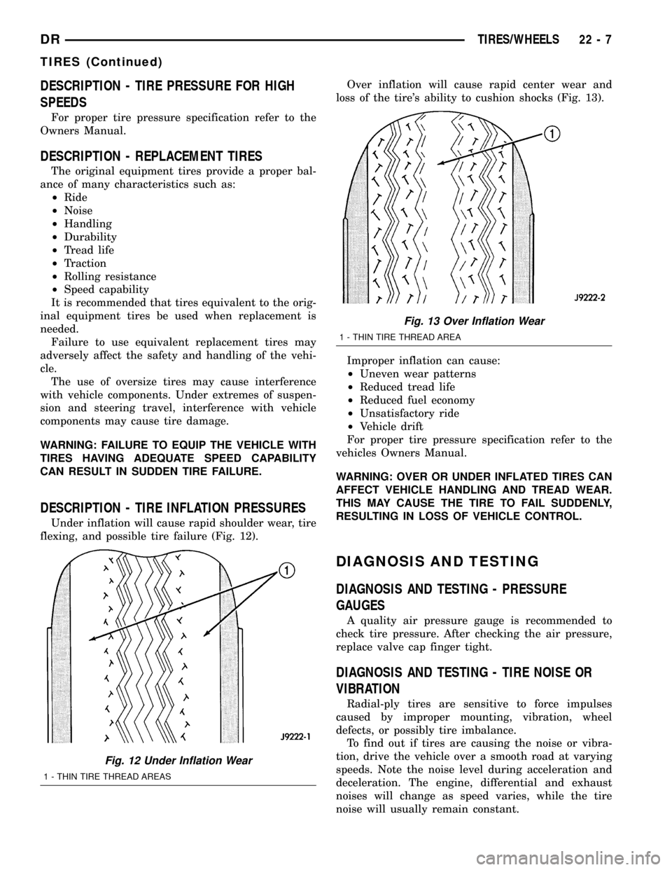
DESCRIPTION - TIRE INFLATION PRESSURES
Under inflation will cause rapid shoulder wear, tire
flexing, and possible tire failure (Fig. 12).Over inflation will cause rapid center wear and
loss of the tire's ability to cushion shocks (Fig. 13).
Improper inflation can cause:
²Uneven wear patterns
²Reduced tread life
²Reduced fuel economy
²Unsatisfactory ride
²Vehicle drift
For proper tire pressure specification refer to the
vehicles Owners Manual.
WARNING: OVER OR UNDER INFLATED TIRES CAN
AFFECT VEHICLE HANDLING AND TREAD WEAR.
THIS MAY CAUSE THE TIRE TO FAIL SUDDENLY,
RESULTING IN LOSS OF VEHICLE CONTROL.
DIAGNOSIS AND TESTING
DIAGNOSIS AND TESTING - PRESSURE
GAUGES
A quality air pressure gauge is recommended to
check tire pressure. After checking the air pressure,
replace valve cap finger tight.
DIAGNOSIS AND TESTING - TIRE NOISE OR
VIBRATION
Radial-ply tires are sensitive to force impulses
caused by improper mounting, vibration, wheel
defects, or possibly tire imbalance.
To find out if tires are causing the noise or vibra-
tion, drive the vehicle over a smooth road at varying
speeds. Note the noise level during acceleration and
deceleration. The engine, differential and exhaust
noises will change as speed varies, while the tire
noise will usually remain constant.
Fig. 12 Under Inflation Wear
1 - THIN TIRE THREAD AREAS
Fig. 13 Over Inflation Wear
1 - THIN TIRE THREAD AREA
DRTIRES/WHEELS 22 - 7
TIRES (Continued)
Page 2564 of 2627

Immediately after a cold start, between predeter-
mined temperature thresholds limits, the three port
solenoid is briefly energized. This initializes the
pump by drawing air into the pump cavity and also
closes the vent seal. During non test conditions the
vent seal is held open by the pump diaphragm
assembly which pushes it open at the full travel posi-
tion. The vent seal will remain closed while the
pump is cycling due to the reed switch triggering of
the three port solenoid that prevents the diaphragm
assembly from reaching full travel. After the brief
initialization period, the solenoid is de-energized
allowing atmospheric pressure to enter the pump
cavity, thus permitting the spring to drive the dia-
phragm which forces air out of the pump cavity and
into the vent system. When the solenoid is energized
and de energized, the cycle is repeated creating flow
in typical diaphragm pump fashion. The pump is con-
trolled in 2 modes:
Pump Mode: The pump is cycled at a fixed rate to
achieve a rapid pressure build in order to shorten the
overall test length.
Test Mode: The solenoid is energized with a fixed
duration pulse. Subsequent fixed pulses occur when
the diaphragm reaches the Switch closure point.
The spring in the pump is set so that the system
will achieve an equalized pressure of about 7.5º H20.
The cycle rate of pump strokes is quite rapid as the
system begins to pump up to this pressure. As the
pressure increases, the cycle rate starts to drop off. If
there is no leak in the system, the pump would even-
tually stop pumping at the equalized pressure. If
there is a leak, it will continue to pump at a rate rep-
resentative of the flow characteristic of the size of the
leak. From this information we can determine if the
leak is larger than the required detection limit (cur-
rently set at .040º orifice by CARB). If a leak is
revealed during the leak test portion of the test, the
test is terminated at the end of the test mode and no
further system checks will be performed.
After passing the leak detection phase of the test,
system pressure is maintained by turning on the
LDP's solenoid until the purge system is activated.
Purge activation in effect creates a leak. The cycle
rate is again interrogated and when it increases due
to the flow through the purge system, the leak check
portion of the diagnostic is complete.
The canister vent valve will unseal the system
after completion of the test sequence as the pump
diaphragm assembly moves to the full travel position.
Evaporative system functionality will be verified by
using the stricter evap purge flow monitor. At an
appropriate warm idle the LDP will be energized to
seal the canister vent. The purge flow will be clocked
up from some small value in an attempt to see a
shift in the 02 control system. If fuel vapor, indicatedby a shift in the 02 control, is present the test is
passed. If not, it is assumed that the purge system is
not functioning in some respect. The LDP is again
turned off and the test is ended.
MISFIRE MONITOR
Excessive engine misfire results in increased cata-
lyst temperature and causes an increase in HC emis-
sions. Severe misfires could cause catalyst damage.
To prevent catalytic convertor damage, the PCM
monitors engine misfire.
The Powertrain Control Module (PCM) monitors
for misfire during most engine operating conditions
(positive torque) by looking at changes in the crank-
shaft speed. If a misfire occurs the speed of the
crankshaft will vary more than normal.
FUEL SYSTEM MONITOR
To comply with clean air regulations, vehicles are
equipped with catalytic converters. These converters
reduce the emission of hydrocarbons, oxides of nitro-
gen and carbon monoxide. The catalyst works best
when the Air Fuel (A/F) ratio is at or near the opti-
mum of 14.7 to 1.
The PCM is programmed to maintain the optimum
air/fuel ratio of 14.7 to 1. This is done by making
short term corrections in the fuel injector pulse width
based on the O2S sensor output. The programmed
memory acts as a self calibration tool that the engine
controller uses to compensate for variations in engine
specifications, sensor tolerances and engine fatigue
over the life span of the engine. By monitoring the
actual fuel-air ratio with the O2S sensor (short term)
and multiplying that with the program long-term
(adaptive) memory and comparing that to the limit,
it can be determined whether it will pass an emis-
sions test. If a malfunction occurs such that the PCM
cannot maintain the optimum A/F ratio, then the
MIL will be illuminated.
CATALYST MONITOR
To comply with clean air regulations, vehicles are
equipped with catalytic converters. These converters
reduce the emission of hydrocarbons, oxides of nitro-
gen and carbon monoxide.
Normal vehicle miles or engine misfire can cause a
catalyst to decay. This can increase vehicle emissions
and deteriorate engine performance, driveability and
fuel economy.
The catalyst monitor uses dual oxygen sensors
(O2S's) to monitor the efficiency of the converter. The
dual O2S's sensor strategy is based on the fact that
as a catalyst deteriorates, its oxygen storage capacity
and its efficiency are both reduced. By monitoring
the oxygen storage capacity of a catalyst, its effi-
ciency can be indirectly calculated. The upstream
DREMISSIONS CONTROL 25 - 3
EMISSIONS CONTROL (Continued)