1998 DODGE RAM 1500 Engine
[x] Cancel search: EnginePage 1315 of 2627
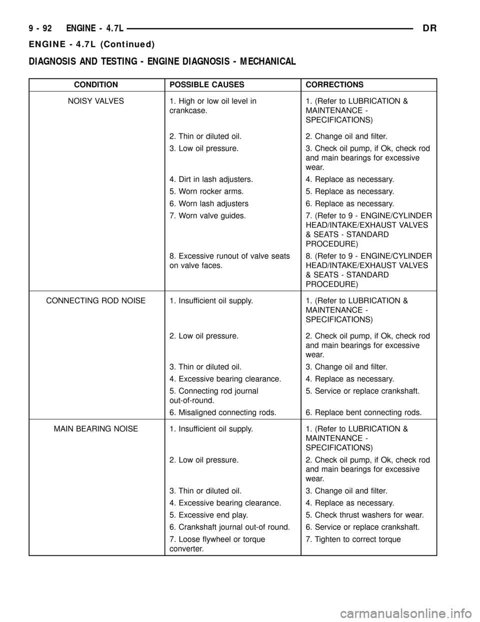
DIAGNOSIS AND TESTING - ENGINE DIAGNOSIS - MECHANICAL
CONDITION POSSIBLE CAUSES CORRECTIONS
NOISY VALVES 1. High or low oil level in
crankcase.1. (Refer to LUBRICATION &
MAINTENANCE -
SPECIFICATIONS)
2. Thin or diluted oil. 2. Change oil and filter.
3. Low oil pressure. 3. Check oil pump, if Ok, check rod
and main bearings for excessive
wear.
4. Dirt in lash adjusters. 4. Replace as necessary.
5. Worn rocker arms. 5. Replace as necessary.
6. Worn lash adjusters 6. Replace as necessary.
7. Worn valve guides. 7. (Refer to 9 - ENGINE/CYLINDER
HEAD/INTAKE/EXHAUST VALVES
& SEATS - STANDARD
PROCEDURE)
8. Excessive runout of valve seats
on valve faces.8. (Refer to 9 - ENGINE/CYLINDER
HEAD/INTAKE/EXHAUST VALVES
& SEATS - STANDARD
PROCEDURE)
CONNECTING ROD NOISE 1. Insufficient oil supply. 1. (Refer to LUBRICATION &
MAINTENANCE -
SPECIFICATIONS)
2. Low oil pressure. 2. Check oil pump, if Ok, check rod
and main bearings for excessive
wear.
3. Thin or diluted oil. 3. Change oil and filter.
4. Excessive bearing clearance. 4. Replace as necessary.
5. Connecting rod journal
out-of-round.5. Service or replace crankshaft.
6. Misaligned connecting rods. 6. Replace bent connecting rods.
MAIN BEARING NOISE 1. Insufficient oil supply. 1. (Refer to LUBRICATION &
MAINTENANCE -
SPECIFICATIONS)
2. Low oil pressure. 2. Check oil pump, if Ok, check rod
and main bearings for excessive
wear.
3. Thin or diluted oil. 3. Change oil and filter.
4. Excessive bearing clearance. 4. Replace as necessary.
5. Excessive end play. 5. Check thrust washers for wear.
6. Crankshaft journal out-of round. 6. Service or replace crankshaft.
7. Loose flywheel or torque
converter.7. Tighten to correct torque
9 - 92 ENGINE - 4.7LDR
ENGINE - 4.7L (Continued)
Page 1316 of 2627
DIAGNOSIS AND TESTING - CYLINDER
COMPRESSION PRESSURE
The results of a cylinder compression pressure test
can be utilized to diagnose several engine malfunc-
tions.
Ensure the battery is completely charged and the
engine starter motor is in good operating condition.
Otherwise the indicated compression pressures may
not be valid for diagnosis purposes.
(1) Clean the spark plug recesses with compressed
air.
(2) Remove the spark plugs.
(3) Disable the fuel system (Refer to 14 - FUEL
SYSTEM/FUEL DELIVERY - DESCRIPTION).
(4) Remove the ASD relay (Refer to 8 - ELECTRI-
CAL/IGNITION CONTROL/AUTO SHUT DOWN
RELAY - REMOVAL).
(5) Insert a compression pressure gauge and rotate
the engine with the engine starter motor for three
revolutions.
(6)
Record the compression pressure on the 3rd revo-
lution. Continue the test for the remaining cylinders.
(7) (Refer to 9 - ENGINE - SPECIFICATIONS) for
the correct engine compression pressures.
DIAGNOSIS AND TESTING - CYLINDER
COMBUSTION PRESSURE LEAKAGE
The combustion pressure leakage test provides an
accurate means for determining engine condition.
Combustion pressure leakage testing will detect:
²
Exhaust and intake valve leaks (improper seating).
²Leaks between adjacent cylinders or into water
jacket.
²Any causes for combustion/compression pressure
loss.
(1) Check the coolant level and fill as required. DO
NOT install the radiator cap.
(2) Start and operate the engine until it attains
normal operating temperature, then turn the engine
OFF.
(3) Remove the spark plugs.
(4) Remove the oil filler cap.
(5) Remove the air cleaner hose.
(6) Calibrate the tester according to the manufac-
turer's instructions. The shop air source for testing
should maintain 483 kPa (70 psi) minimum, 1,379
kPa (200 psi) maximum and 552 kPa (80 psi) recom-
mended.
(7) Perform the test procedures on each cylinder
according to the tester manufacturer's instructions.
Set piston of cylinder to be tested at TDC compres-
sion,While testing, listen for pressurized air escaping
through the throttle body, tailpipe and oil filler cap
opening. Check for bubbles in the radiator coolant.
All gauge pressure indications should be equal,
with no more than 25% leakage.
FOR EXAMPLE:At 552 kPa (80 psi) input pres-
sure, a minimum of 414 kPa (60 psi) should be main-
tained in the cylinder.
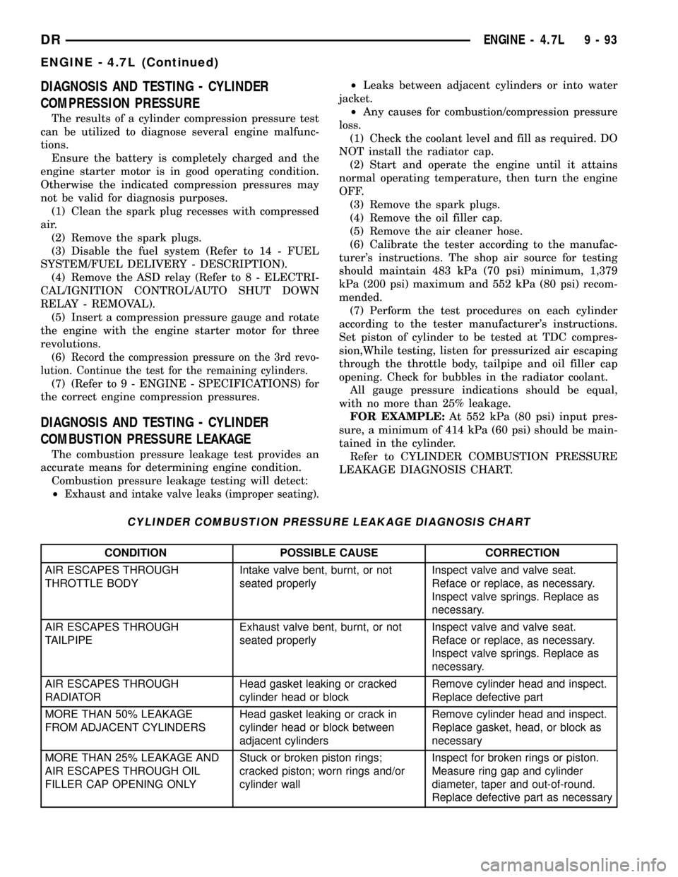
Refer to CYLINDER COMBUSTION PRESSURE
LEAKAGE DIAGNOSIS CHART.
CYLINDER COMBUSTION PRESSURE LEAKAGE DIAGNOSIS CHART
CONDITION POSSIBLE CAUSE CORRECTION
AIR ESCAPES THROUGH
THROTTLE BODYIntake valve bent, burnt, or not
seated properlyInspect valve and valve seat.
Reface or replace, as necessary.
Inspect valve springs. Replace as
necessary.
AIR ESCAPES THROUGH
TAILPIPEExhaust valve bent, burnt, or not
seated properlyInspect valve and valve seat.
Reface or replace, as necessary.
Inspect valve springs. Replace as
necessary.
AIR ESCAPES THROUGH
RADIATORHead gasket leaking or cracked
cylinder head or blockRemove cylinder head and inspect.
Replace defective part
MORE THAN 50% LEAKAGE
FROM ADJACENT CYLINDERSHead gasket leaking or crack in
cylinder head or block between
adjacent cylindersRemove cylinder head and inspect.
Replace gasket, head, or block as
necessary
MORE THAN 25% LEAKAGE AND
AIR ESCAPES THROUGH OIL
FILLER CAP OPENING ONLYStuck or broken piston rings;
cracked piston; worn rings and/or
cylinder wallInspect for broken rings or piston.
Measure ring gap and cylinder
diameter, taper and out-of-round.
Replace defective part as necessary
DRENGINE - 4.7L 9 - 93
ENGINE - 4.7L (Continued)
Page 1317 of 2627

DIAGNOSIS AND TESTING - ENGINE
DIAGNOSIS - INTRODUCTION
Engine diagnosis is helpful in determining the
causes of malfunctions not detected and remedied by
routine maintenance.
These malfunctions may be classified as either per-
formance (e.g., engine idles rough and stalls) or
mechanical (e.g., a strange noise).
(Refer to 9 - ENGINE - DIAGNOSIS AND TEST-
ING) - PERFORMANCE and (Refer to 9 - ENGINE -
DIAGNOSIS AND TESTING)ÐMECHANICAL for
possible causes and corrections of malfunctions.
(Refer to 14 - FUEL SYSTEM/FUEL DELIVERY -
DIAGNOSIS AND TESTING) and (Refer to 14 -
FUEL SYSTEM/FUEL INJECTION - DIAGNOSIS
AND TESTING) for the fuel system diagnosis.
Additional tests and diagnostic procedures may be
necessary for specific engine malfunctions that can
not be isolated with the Service Diagnosis charts.
Information concerning additional tests and diagno-
sis is provided within the following diagnosis:
²Cylinder Compression Pressure Test (Refer to 9 -
ENGINE - DIAGNOSIS AND TESTING).
²Cylinder Combustion Pressure Leakage Test
(Refer to 9 - ENGINE - DIAGNOSIS AND TEST-
ING).
²Engine Cylinder Head Gasket Failure Diagnosis
(Refer to 9 - ENGINE/CYLINDER HEAD - DIAGNO-
SIS AND TESTING).
²Intake Manifold Leakage Diagnosis (Refer to 9 -
ENGINE/MANIFOLDS/INTAKE MANIFOLD -
DIAGNOSIS AND TESTING).
STANDARD PROCEDURE
STANDARD PROCEDURE - REPAIR DAMAGED
OR WORN THREADS
CAUTION: Be sure that the tapped holes maintain
the original center line.
Damaged or worn threads can be repaired. Essen-
tially, this repair consists of:
²Drilling out worn or damaged threads.
²Tapping the hole with a special Heli-Coil Tap, or
equivalent.
²Installing an insert into the tapped hole to bring
the hole back to its original thread size.
STANDARD PROCEDURE - FORM-IN-PLACE
GASKETS AND SEALERS
There are numerous places where form-in-place
gaskets are used on the engine. Care must be taken
when applying form-in-place gaskets to assure
obtaining the desired results.Do not use form-in-place gasket material unless specified.Bead size,
continuity, and location are of great importance. Too
thin a bead can result in leakage while too much can
result in spill-over which can break off and obstruct
fluid feed lines. A continuous bead of the proper
width is essential to obtain a leak-free gasket.
There are numerous types of form-in-place gasket
materials that are used in the engine area. Mopart
Engine RTV GEN II, MopartATF-RTV, and Mopart
Gasket Maker gasket materials, each have different
properties and can not be used in place of the other.
MOPARtENGINE RTV GEN II
MopartEngine RTV GEN II is used to seal com-
ponents exposed to engine oil. This material is a spe-
cially designed black silicone rubber RTV that
retains adhesion and sealing properties when
exposed to engine oil. Moisture in the air causes the
material to cure. This material is available in three
ounce tubes and has a shelf life of one year. After one
year this material will not properly cure. Always
inspect the package for the expiration date before
use.
MOPARtATF RTV
MopartATF RTV is a specifically designed black
silicone rubber RTV that retains adhesion and seal-
ing properties to seal components exposed to auto-
matic transmission fluid, engine coolants, and
moisture. This material is available in three ounce
tubes and has a shelf life of one year. After one year
this material will not properly cure. Always inspect
the package for the expiration date before use.
MOPARtGASKET MAKER
MopartGasket Maker is an anaerobic type gasket
material. The material cures in the absence of air
when squeezed between two metallic surfaces. It will
not cure if left in the uncovered tube. The anaerobic
material is for use between two machined surfaces.
Do not use on flexible metal flanges.
MOPARtGASKET SEALANT
MopartGasket Sealant is a slow drying, perma-
nently soft sealer. This material is recommended for
sealing threaded fittings and gaskets against leakage
of oil and coolant. Can be used on threaded and
machined parts under all temperatures. This mate-
rial is used on engines with multi-layer steel (MLS)
cylinder head gaskets. This material also will pre-
vent corrosion. MopartGasket Sealant is available in
a 13 oz. aerosol can or 4oz./16 oz. can w/applicator.
FORM-IN-PLACE GASKET AND SEALER
APPLICATION
Assembling parts using a form-in-place gasket
requires care but it's easier than using precut gas-
kets.
MopartGasket Maker material should be applied
sparingly 1 mm (0.040 in.) diameter or less of sealant
9 - 94 ENGINE - 4.7LDR
ENGINE - 4.7L (Continued)
Page 1318 of 2627
to one gasket surface. Be certain the material sur-
rounds each mounting hole. Excess material can eas-
ily be wiped off. Components should be torqued in
place within 15 minutes. The use of a locating dowel
is recommended during assembly to prevent smear-
ing material off the location.
MopartEngine RTV GEN II or ATF RTV gasket
material should be applied in a continuous bead
approximately 3 mm (0.120 in.) in diameter. All
mounting holes must be circled. For corner sealing, a
3.17 or 6.35 mm (1/8 or 1/4 in.) drop is placed in the
center of the gasket contact area. Uncured sealant
may be removed with a shop towel. Components
should be torqued in place while the sealant is still
wet to the touch (within 10 minutes). The usage of a
locating dowel is recommended during assembly to
prevent smearing material off the location.
MopartGasket Sealant in an aerosol can should be
applied using a thin, even coat sprayed completely
over both surfaces to be joined, and both sides of a
gasket. Then proceed with assembly. Material in a
can w/applicator can be brushed on evenly over the
sealing surfaces. Material in an aerosol can should be
used on engines with multi-layer steel gaskets.
REMOVAL
NOTE: This procedure applies to both the 4X2 and
4X4 vehicles, steps that apply to the 4X4 vehicle
only, are identified.
(1) Disconnect the battery negative and positive
cables.
(2) Remove the battery and the battery tray.
(3) Raise vehicle on hoist.
(4) Remove exhaust crossover pipe from exhaust
manifolds.
(5)4X4 vehiclesDisconnect axle vent tube from
left side engine mount.
(6) Remove the through bolt retaining nut and bolt
from both the left and right side engine mounts.
(7)4X4 vehiclesRemove locknut from left and
right side engine mount brackets.
(8) Disconnect two ground straps from the lower
left hand side and one ground strap from the lower
right hand side of the engine.
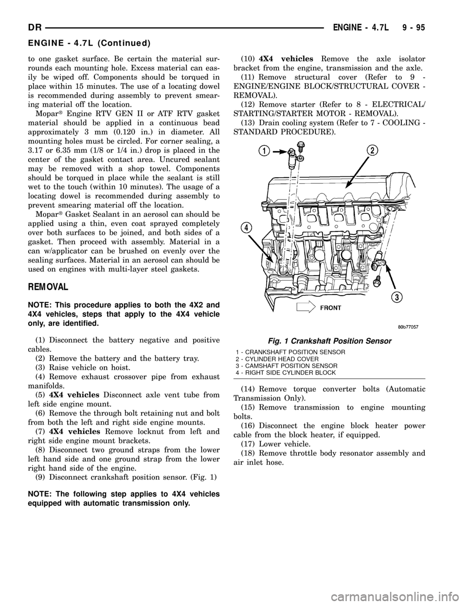
(9) Disconnect crankshaft position sensor. (Fig. 1)
NOTE: The following step applies to 4X4 vehicles
equipped with automatic transmission only.(10)4X4 vehiclesRemove the axle isolator
bracket from the engine, transmission and the axle.
(11) Remove structural cover (Refer to 9 -
ENGINE/ENGINE BLOCK/STRUCTURAL COVER -
REMOVAL).
(12) Remove starter (Refer to 8 - ELECTRICAL/
STARTING/STARTER MOTOR - REMOVAL).
(13) Drain cooling system (Refer to 7 - COOLING -
STANDARD PROCEDURE).
(14) Remove torque converter bolts (Automatic
Transmission Only).
(15) Remove transmission to engine mounting
bolts.
(16) Disconnect the engine block heater power
cable from the block heater, if equipped.
(17) Lower vehicle.
(18) Remove throttle body resonator assembly and
air inlet hose.
Fig. 1 Crankshaft Position Sensor
1 - CRANKSHAFT POSITION SENSOR
2 - CYLINDER HEAD COVER
3 - CAMSHAFT POSITION SENSOR
4 - RIGHT SIDE CYLINDER BLOCK
DRENGINE - 4.7L 9 - 95
ENGINE - 4.7L (Continued)
Page 1319 of 2627
(19) Disconnect throttle and speed control cables.
(20) Disconnect tube from both the left and right
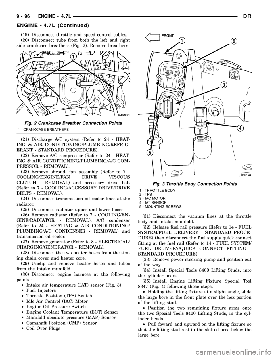
side crankcase breathers (Fig. 2). Remove breathers
(21) Discharge A/C system (Refer to 24 - HEAT-
ING & AIR CONDITIONING/PLUMBING/REFRIG-
ERANT - STANDARD PROCEDURE).
(22) Remove A/C compressor (Refer to 24 - HEAT-
ING & AIR CONDITIONING/PLUMBING/A/C COM-
PRESSOR - REMOVAL).
(23) Remove shroud, fan assembly (Refer to 7 -
COOLING/ENGINE/FAN DRIVE VISCOUS
CLUTCH - REMOVAL) and accessory drive belt
(Refer to 7 - COOLING/ACCESSORY DRIVE/DRIVE
BELTS - REMOVAL).
(24) Disconnect transmission oil cooler lines at the
radiator.
(25) Disconnect radiator upper and lower hoses.
(26) Remove radiator (Refer to 7 - COOLING/EN-
GINE/RADIATOR - REMOVAL), A/C condenser
(Refer to 24 - HEATING & AIR CONDITIONING/
PLUMBING/A/C CONDENSER - REMOVAL) and
transmission oil cooler.
(27) Remove generator (Refer to 8 - ELECTRICAL/
CHARGING/GENERATOR - REMOVAL).
(28) Disconnect the two heater hoses from the tim-
ing chain cover and heater core.
(29) Unclip and remove heater hoses and tubes
from the intake manifold.
(30) Disconnect engine harness at the following
points :
²Intake air temperature (IAT) sensor (Fig. 3)
²Fuel Injectors
²Throttle Position (TPS) Switch
²Idle Air Control (IAC) Motor
²Engine Oil Pressure Switch
²Engine Coolant Temperature (ECT) Sensor
²Manifold absolute pressure (MAP) Sensor
²Camshaft Position (CMP) Sensor
²Coil Over Plugs(31) Disconnect the vacuum lines at the throttle
body and intake manifold.
(32) Release fuel rail pressure (Refer to 14 - FUEL
SYSTEM/FUEL DELIVERY - STANDARD PROCE-
DURE) then disconnect the fuel supply quick connect
fitting at the fuel rail (Refer to 14 - FUEL SYSTEM/
FUEL DELIVERY/QUICK CONNECT FITTING -
STANDARD PROCEDURE).
(33) Remove power steering pump and position out
of the way.
(34) Install Special Tools 8400 Lifting Studs, into
the cylinder heads.
(35) Install Engine Lifting Fixture Special Tool
8347 (Fig. 4) following these steps.
²Holding the lifting fixture at a slight angle, slide
the large bore in the front plate over the hex portion
of the lifting stud.
²Position the two remaining fixture arms onto
the two Special Tools 8400 Lifting Studs, in the cyl-
inder heads.
²Pull foward and upward on the lifting fixture so
that the lifting stud rest in the slotted area below the
large bore.
Fig. 2 Crankcase Breather Connection Points
1 - CRANKCASE BREATHERS
Fig. 3 Throttle Body Connection Points
1 - THROTTLE BODY
2 - TPS
3 - IAC MOTOR
4 - IAT SENSOR
5 - MOUNTING SCREWS
9 - 96 ENGINE - 4.7LDR
ENGINE - 4.7L (Continued)
Page 1320 of 2627
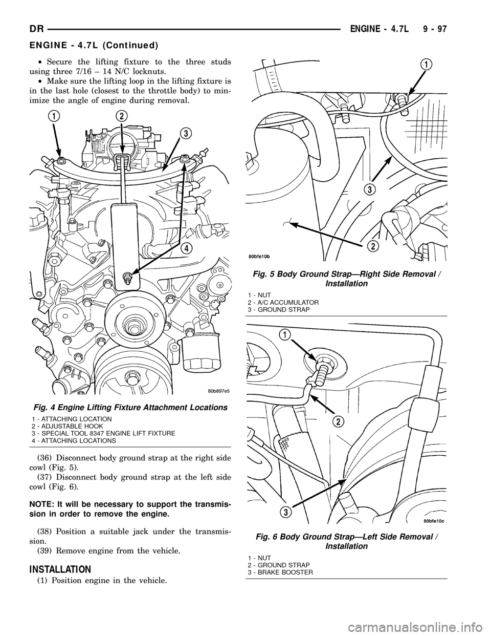
²Secure the lifting fixture to the three studs
using three 7/16 ± 14 N/C locknuts.
²Make sure the lifting loop in the lifting fixture is
in the last hole (closest to the throttle body) to min-
imize the angle of engine during removal.
(36) Disconnect body ground strap at the right side
cowl (Fig. 5).
(37) Disconnect body ground strap at the left side
cowl (Fig. 6).
NOTE: It will be necessary to support the transmis-
sion in order to remove the engine.
(38) Position a suitable jack under the transmis-
sion.
(39) Remove engine from the vehicle.
INSTALLATION
(1) Position engine in the vehicle.
Fig. 4 Engine Lifting Fixture Attachment Locations
1 - ATTACHING LOCATION
2 - ADJUSTABLE HOOK
3 - SPECIAL TOOL 8347 ENGINE LIFT FIXTURE
4 - ATTACHING LOCATIONS
Fig. 5 Body Ground StrapÐRight Side Removal /
Installation
1 - NUT
2 - A/C ACCUMULATOR
3 - GROUND STRAP
Fig. 6 Body Ground StrapÐLeft Side Removal /
Installation
1 - NUT
2 - GROUND STRAP
3 - BRAKE BOOSTER
DRENGINE - 4.7L 9 - 97
ENGINE - 4.7L (Continued)
Page 1321 of 2627

Position both the left and right side engine mount
brackets and install the through bolts and nuts.
Tighten nuts to4X2 vehicles95 N´m (70 ft. lbs.).
4X4 vehicles102 N´m (75 ft. lbs.).
(2)4X4 vehiclesInstall locknuts onto the engine
mount brackets. Tighten locknuts to 41 N´m (30 ft.
lbs.).
(3) Remove jack from under the transmission.
(4) Remove Engine Lifting Fixture Special Tool
8347 (Fig. 4).
(5) Remove Special Tools 8400 Lifting Studs.
(6) Position generator wiring behind the oil dip-
stick tube, then install the oil dipstick tube upper
mounting bolt.
(7) Connect both left and right side body ground
straps.
(8) Install power steering pump.
(9) Connect fuel supply line quick connect fitting
(Refer to 14 - FUEL SYSTEM/FUEL DELIVERY/
QUICK CONNECT FITTING - STANDARD PROCE-
DURE).
(10) Connect the vacuum lines at the throttle body
and intake manifold.
(11) Connect engine harness at the following
points (Fig. 3):
²Intake Air Temperature (IAT) Sensor
²Idle Air Control (IAC) Motor
²Fuel Injectors
²Throttle Position (TPS) Switch
²Engine Oil Pressure Switch
²Engine Coolant Temperature (ECT) Sensor
²Manifold Absolute Pressure (MAP) Sensor
²Camshaft Position (CMP) Sensor
²Coil Over Plugs
(12) Position and install heater hoses and tubes
onto intake manifold.
(13) Install the heater hoses onto the heater core
and the engine front cover.
(14) Install generator (Refer to 8 - ELECTRICAL/
CHARGING/GENERATOR - INSTALLATION).
(15) Install A/C condenser (Refer to 24 - HEATING
& AIR CONDITIONING/PLUMBING/A/C CON-
DENSER - INSTALLATION), radiator (Refer to 7 -
COOLING/ENGINE/RADIATOR - INSTALLATION)
and transmission oil cooler.
(16) Connect radiator upper and lower hoses.
(17) Connect the transmission oil cooler lines to
the radiator.
(18) Install accessory drive belt (Refer to 7 -
COOLING/ACCESSORY DRIVE/DRIVE BELTS -INSTALLATION), fan assembly and shroud (Refer to
7 - COOLING/ENGINE/FAN DRIVE VISCOUS
CLUTCH - INSTALLATION).
(19) Install A/C compressor (Refer to 24 - HEAT-
ING & AIR CONDITIONING/PLUMBING/A/C COM-
PRESSOR - INSTALLATION).
(20) Install both breathers. Connect tube to both
crankcase breathers (Fig. 2).
(21) Connect throttle and speed control cables.
(22) Install throttle body resonator assembly and
air inlet hose. Tighten clamps 4 N´m (35 in. lbs.).
(23) Raise vehicle.
(24) Install transmission to engine mounting bolts.
Tighten the bolts to 41 N´m (30 ft. lbs.).
(25) Install torque converter bolts (Automatic
Transmission Only).
(26) Connect crankshaft position sensor (Fig. 1).
(27)4X4 vehiclesPosition and install the axle
isolator bracket onto the axle, transmission and
engine block. Tighten bolts to specification (Refer to 9
- ENGINE - SPECIFICATIONS).
(28) Install starter (Refer to 8 - ELECTRICAL/
STARTING/STARTER MOTOR - INSTALLATION).
CAUTION: The structural cover requires a specific
torque sequence. Failure to follow this sequence
may cause severe damage to the cover.
(29) Install structural cover (Refer to 9 - ENGINE/
ENGINE BLOCK/STRUCTURAL COVER - INSTAL-
LATION).
(30) Install exhaust crossover pipe.
(31) Install engine block heater power cable, If
equipped.
(32)4X4 vehiclesConnect axle vent tube to left
side engine mount.
(33) Lower vehicle.
(34) Check and fill engine oil.
(35) Recharge the A/C system (Refer to 24 - HEAT-
ING & AIR CONDITIONING/PLUMBING/REFRIG-
ERANT - STANDARD PROCEDURE).
(36) Refill the engine cooling system (Refer to 7 -
COOLING - STANDARD PROCEDURE).
(37) Install the battery tray and battery.
(38) Connect the battery positive and negative
cables.
(39) Start the engine and check for leaks.
9 - 98 ENGINE - 4.7LDR
ENGINE - 4.7L (Continued)
Page 1322 of 2627
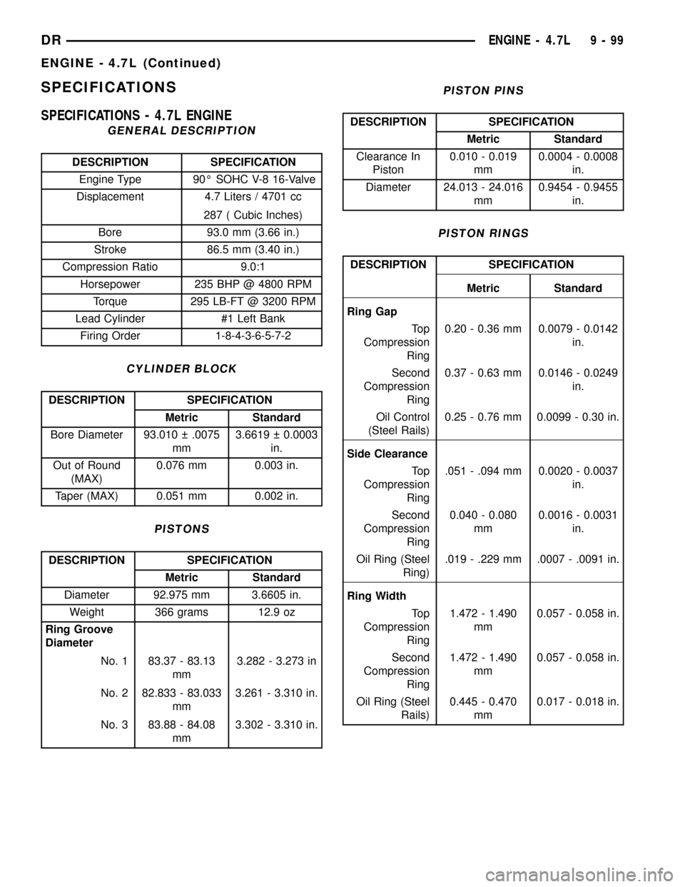
SPECIFICATIONS
SPECIFICATIONS - 4.7L ENGINE
GENERAL DESCRIPTION
DESCRIPTION SPECIFICATION
Engine Type 90É SOHC V-8 16-Valve
Displacement 4.7 Liters / 4701 cc
287 ( Cubic Inches)
Bore 93.0 mm (3.66 in.)
Stroke 86.5 mm (3.40 in.)
Compression Ratio 9.0:1
Horsepower 235 BHP @ 4800 RPM
Torque 295 LB-FT @ 3200 RPM
Lead Cylinder #1 Left Bank
Firing Order 1-8-4-3-6-5-7-2
CYLINDER BLOCK
DESCRIPTION SPECIFICATION
Metric Standard
Bore Diameter 93.010 .0075
mm3.6619 0.0003
in.
Out of Round
(MAX)0.076 mm 0.003 in.
Taper (MAX) 0.051 mm 0.002 in.
PISTONS
DESCRIPTION SPECIFICATION
Metric Standard
Diameter 92.975 mm 3.6605 in.
Weight 366 grams 12.9 oz
Ring Groove
Diameter
No. 1 83.37 - 83.13
mm3.282 - 3.273 in
No. 2 82.833 - 83.033
mm3.261 - 3.310 in.
No. 3 83.88 - 84.08
mm3.302 - 3.310 in.
PISTON PINS
DESCRIPTION SPECIFICATION
Metric Standard
Clearance In
Piston0.010 - 0.019
mm0.0004 - 0.0008
in.
Diameter 24.013 - 24.016
mm0.9454 - 0.9455
in.
PISTON RINGS
DESCRIPTION SPECIFICATION
Metric Standard
Ring Gap
To p
Compression
Ring0.20 - 0.36 mm 0.0079 - 0.0142
in.
Second
Compression
Ring0.37 - 0.63 mm 0.0146 - 0.0249
in.
Oil Control
(Steel Rails)0.25 - 0.76 mm 0.0099 - 0.30 in.
Side Clearance
To p
Compression
Ring.051 - .094 mm 0.0020 - 0.0037
in.
Second
Compression
Ring0.040 - 0.080
mm0.0016 - 0.0031
in.
Oil Ring (Steel
Ring).019 - .229 mm .0007 - .0091 in.
Ring Width
To p
Compression
Ring1.472 - 1.490
mm0.057 - 0.058 in.
Second
Compression
Ring1.472 - 1.490
mm0.057 - 0.058 in.
Oil Ring (Steel
Rails)0.445 - 0.470
mm0.017 - 0.018 in.
DRENGINE - 4.7L 9 - 99
ENGINE - 4.7L (Continued)