1998 DODGE RAM 1500 heater fan
[x] Cancel search: heater fanPage 1305 of 2627
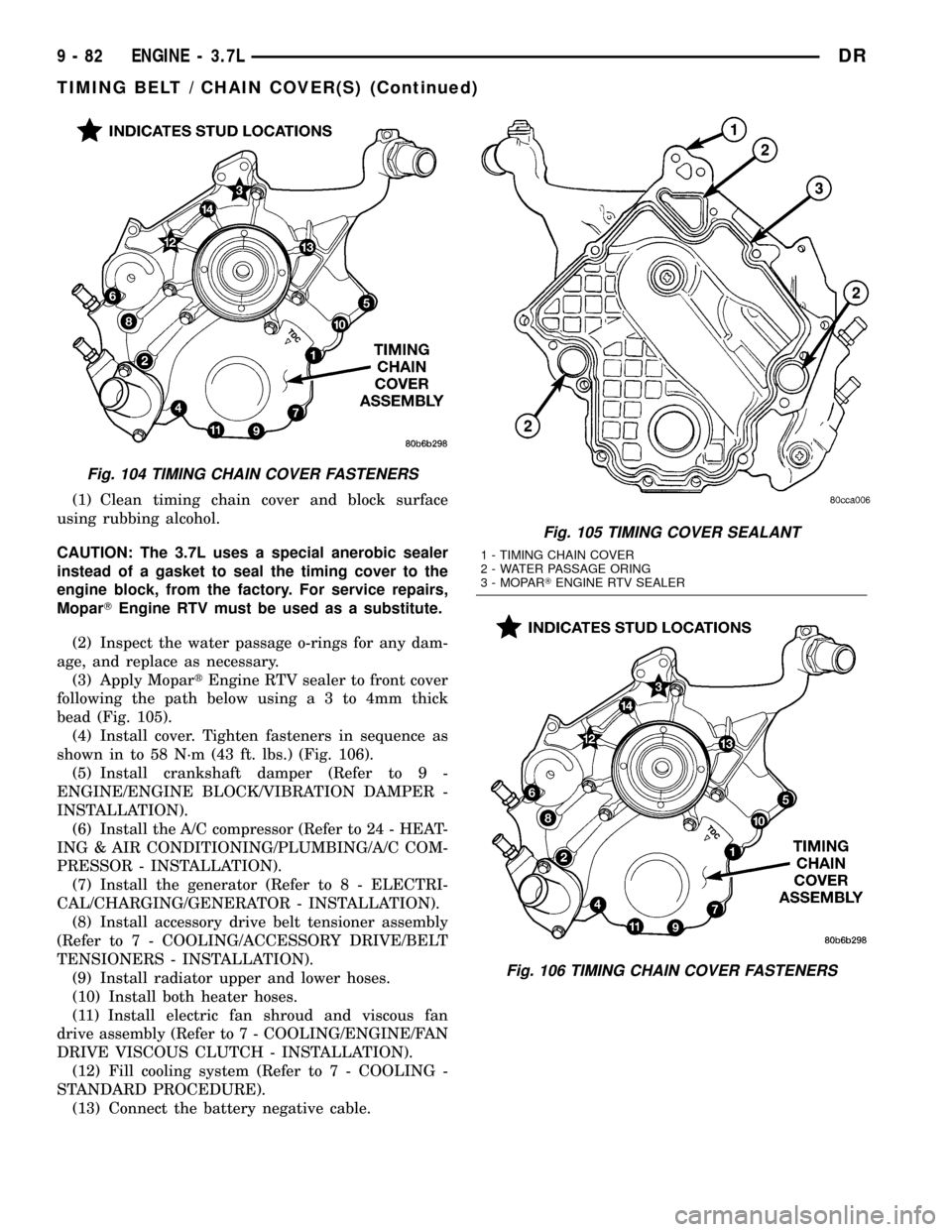
(1) Clean timing chain cover and block surface
using rubbing alcohol.
CAUTION: The 3.7L uses a special anerobic sealer
instead of a gasket to seal the timing cover to the
engine block, from the factory. For service repairs,
MoparTEngine RTV must be used as a substitute.
(2) Inspect the water passage o-rings for any dam-
age, and replace as necessary.
(3) Apply MopartEngine RTV sealer to front cover
following the path below usinga3to4mmthick
bead (Fig. 105).
(4) Install cover. Tighten fasteners in sequence as
shown in to 58 N´m (43 ft. lbs.) (Fig. 106).
(5) Install crankshaft damper (Refer to 9 -
ENGINE/ENGINE BLOCK/VIBRATION DAMPER -
INSTALLATION).
(6) Install the A/C compressor (Refer to 24 - HEAT-
ING & AIR CONDITIONING/PLUMBING/A/C COM-
PRESSOR - INSTALLATION).
(7) Install the generator (Refer to 8 - ELECTRI-
CAL/CHARGING/GENERATOR - INSTALLATION).
(8) Install accessory drive belt tensioner assembly
(Refer to 7 - COOLING/ACCESSORY DRIVE/BELT
TENSIONERS - INSTALLATION).
(9) Install radiator upper and lower hoses.
(10) Install both heater hoses.
(11) Install electric fan shroud and viscous fan
drive assembly (Refer to 7 - COOLING/ENGINE/FAN
DRIVE VISCOUS CLUTCH - INSTALLATION).
(12) Fill cooling system (Refer to 7 - COOLING -
STANDARD PROCEDURE).
(13) Connect the battery negative cable.
Fig. 104 TIMING CHAIN COVER FASTENERS
Fig. 105 TIMING COVER SEALANT
1 - TIMING CHAIN COVER
2 - WATER PASSAGE ORING
3 - MOPARTENGINE RTV SEALER
Fig. 106 TIMING CHAIN COVER FASTENERS
9 - 82 ENGINE - 3.7LDR
TIMING BELT / CHAIN COVER(S) (Continued)
Page 1319 of 2627
(19) Disconnect throttle and speed control cables.
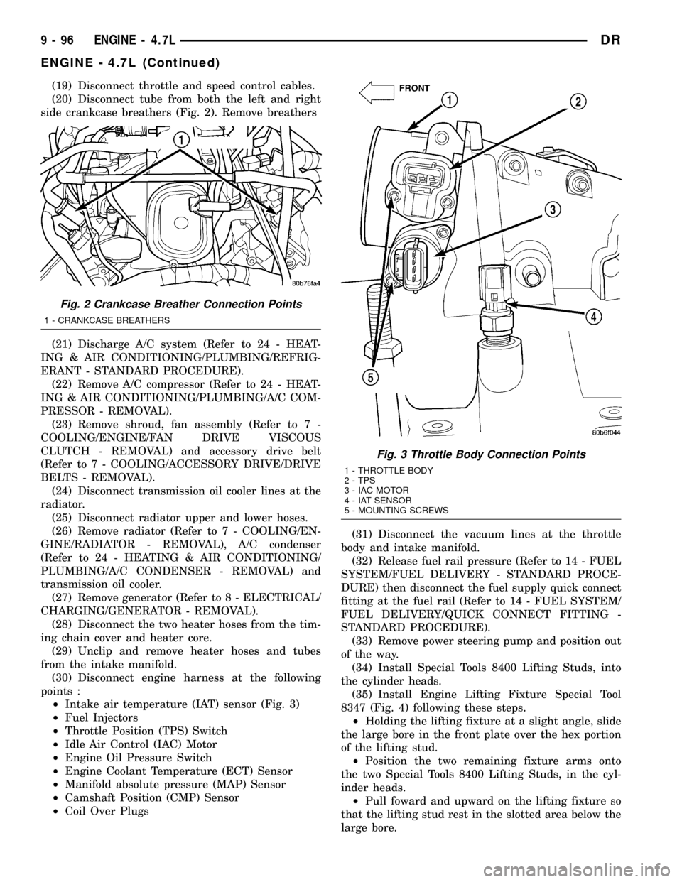
(20) Disconnect tube from both the left and right
side crankcase breathers (Fig. 2). Remove breathers
(21) Discharge A/C system (Refer to 24 - HEAT-
ING & AIR CONDITIONING/PLUMBING/REFRIG-
ERANT - STANDARD PROCEDURE).
(22) Remove A/C compressor (Refer to 24 - HEAT-
ING & AIR CONDITIONING/PLUMBING/A/C COM-
PRESSOR - REMOVAL).
(23) Remove shroud, fan assembly (Refer to 7 -
COOLING/ENGINE/FAN DRIVE VISCOUS
CLUTCH - REMOVAL) and accessory drive belt
(Refer to 7 - COOLING/ACCESSORY DRIVE/DRIVE
BELTS - REMOVAL).
(24) Disconnect transmission oil cooler lines at the
radiator.
(25) Disconnect radiator upper and lower hoses.
(26) Remove radiator (Refer to 7 - COOLING/EN-
GINE/RADIATOR - REMOVAL), A/C condenser
(Refer to 24 - HEATING & AIR CONDITIONING/
PLUMBING/A/C CONDENSER - REMOVAL) and
transmission oil cooler.
(27) Remove generator (Refer to 8 - ELECTRICAL/
CHARGING/GENERATOR - REMOVAL).
(28) Disconnect the two heater hoses from the tim-
ing chain cover and heater core.
(29) Unclip and remove heater hoses and tubes
from the intake manifold.
(30) Disconnect engine harness at the following
points :
²Intake air temperature (IAT) sensor (Fig. 3)
²Fuel Injectors
²Throttle Position (TPS) Switch
²Idle Air Control (IAC) Motor
²Engine Oil Pressure Switch
²Engine Coolant Temperature (ECT) Sensor
²Manifold absolute pressure (MAP) Sensor
²Camshaft Position (CMP) Sensor
²Coil Over Plugs(31) Disconnect the vacuum lines at the throttle
body and intake manifold.
(32) Release fuel rail pressure (Refer to 14 - FUEL
SYSTEM/FUEL DELIVERY - STANDARD PROCE-
DURE) then disconnect the fuel supply quick connect
fitting at the fuel rail (Refer to 14 - FUEL SYSTEM/
FUEL DELIVERY/QUICK CONNECT FITTING -
STANDARD PROCEDURE).
(33) Remove power steering pump and position out
of the way.
(34) Install Special Tools 8400 Lifting Studs, into
the cylinder heads.
(35) Install Engine Lifting Fixture Special Tool
8347 (Fig. 4) following these steps.
²Holding the lifting fixture at a slight angle, slide
the large bore in the front plate over the hex portion
of the lifting stud.
²Position the two remaining fixture arms onto
the two Special Tools 8400 Lifting Studs, in the cyl-
inder heads.
²Pull foward and upward on the lifting fixture so
that the lifting stud rest in the slotted area below the
large bore.
Fig. 2 Crankcase Breather Connection Points
1 - CRANKCASE BREATHERS
Fig. 3 Throttle Body Connection Points
1 - THROTTLE BODY
2 - TPS
3 - IAC MOTOR
4 - IAT SENSOR
5 - MOUNTING SCREWS
9 - 96 ENGINE - 4.7LDR
ENGINE - 4.7L (Continued)
Page 1321 of 2627
Position both the left and right side engine mount
brackets and install the through bolts and nuts.
Tighten nuts to4X2 vehicles95 N´m (70 ft. lbs.).
4X4 vehicles102 N´m (75 ft. lbs.).
(2)4X4 vehiclesInstall locknuts onto the engine
mount brackets. Tighten locknuts to 41 N´m (30 ft.
lbs.).
(3) Remove jack from under the transmission.
(4) Remove Engine Lifting Fixture Special Tool
8347 (Fig. 4).
(5) Remove Special Tools 8400 Lifting Studs.
(6) Position generator wiring behind the oil dip-
stick tube, then install the oil dipstick tube upper
mounting bolt.
(7) Connect both left and right side body ground
straps.
(8) Install power steering pump.
(9) Connect fuel supply line quick connect fitting
(Refer to 14 - FUEL SYSTEM/FUEL DELIVERY/
QUICK CONNECT FITTING - STANDARD PROCE-
DURE).
(10) Connect the vacuum lines at the throttle body
and intake manifold.
(11) Connect engine harness at the following
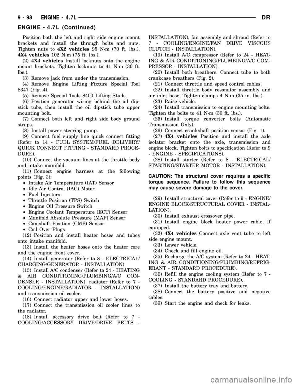
points (Fig. 3):
²Intake Air Temperature (IAT) Sensor
²Idle Air Control (IAC) Motor
²Fuel Injectors
²Throttle Position (TPS) Switch
²Engine Oil Pressure Switch
²Engine Coolant Temperature (ECT) Sensor
²Manifold Absolute Pressure (MAP) Sensor
²Camshaft Position (CMP) Sensor
²Coil Over Plugs
(12) Position and install heater hoses and tubes
onto intake manifold.
(13) Install the heater hoses onto the heater core
and the engine front cover.
(14) Install generator (Refer to 8 - ELECTRICAL/
CHARGING/GENERATOR - INSTALLATION).
(15) Install A/C condenser (Refer to 24 - HEATING
& AIR CONDITIONING/PLUMBING/A/C CON-
DENSER - INSTALLATION), radiator (Refer to 7 -
COOLING/ENGINE/RADIATOR - INSTALLATION)
and transmission oil cooler.
(16) Connect radiator upper and lower hoses.
(17) Connect the transmission oil cooler lines to
the radiator.
(18) Install accessory drive belt (Refer to 7 -
COOLING/ACCESSORY DRIVE/DRIVE BELTS -INSTALLATION), fan assembly and shroud (Refer to
7 - COOLING/ENGINE/FAN DRIVE VISCOUS
CLUTCH - INSTALLATION).
(19) Install A/C compressor (Refer to 24 - HEAT-
ING & AIR CONDITIONING/PLUMBING/A/C COM-
PRESSOR - INSTALLATION).
(20) Install both breathers. Connect tube to both
crankcase breathers (Fig. 2).
(21) Connect throttle and speed control cables.
(22) Install throttle body resonator assembly and
air inlet hose. Tighten clamps 4 N´m (35 in. lbs.).
(23) Raise vehicle.
(24) Install transmission to engine mounting bolts.
Tighten the bolts to 41 N´m (30 ft. lbs.).
(25) Install torque converter bolts (Automatic
Transmission Only).
(26) Connect crankshaft position sensor (Fig. 1).
(27)4X4 vehiclesPosition and install the axle
isolator bracket onto the axle, transmission and
engine block. Tighten bolts to specification (Refer to 9
- ENGINE - SPECIFICATIONS).
(28) Install starter (Refer to 8 - ELECTRICAL/
STARTING/STARTER MOTOR - INSTALLATION).
CAUTION: The structural cover requires a specific
torque sequence. Failure to follow this sequence
may cause severe damage to the cover.
(29) Install structural cover (Refer to 9 - ENGINE/
ENGINE BLOCK/STRUCTURAL COVER - INSTAL-
LATION).
(30) Install exhaust crossover pipe.
(31) Install engine block heater power cable, If
equipped.
(32)4X4 vehiclesConnect axle vent tube to left
side engine mount.
(33) Lower vehicle.
(34) Check and fill engine oil.
(35) Recharge the A/C system (Refer to 24 - HEAT-
ING & AIR CONDITIONING/PLUMBING/REFRIG-
ERANT - STANDARD PROCEDURE).
(36) Refill the engine cooling system (Refer to 7 -
COOLING - STANDARD PROCEDURE).
(37) Install the battery tray and battery.
(38) Connect the battery positive and negative
cables.
(39) Start the engine and check for leaks.
9 - 98 ENGINE - 4.7LDR
ENGINE - 4.7L (Continued)
Page 1382 of 2627
INSTALLATION
(1) Position the oil pump onto the crankshaft and
install one oil pump retaining bolts.
(2) Position the primary timing chain tensioner
and install three retaining bolts.
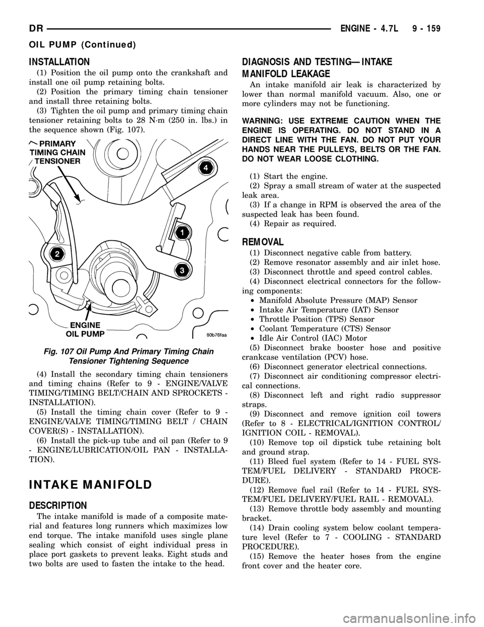
(3) Tighten the oil pump and primary timing chain
tensioner retaining bolts to 28 N´m (250 in. lbs.) in
the sequence shown (Fig. 107).
(4) Install the secondary timing chain tensioners
and timing chains (Refer to 9 - ENGINE/VALVE
TIMING/TIMING BELT/CHAIN AND SPROCKETS -
INSTALLATION).
(5) Install the timing chain cover (Refer to 9 -
ENGINE/VALVE TIMING/TIMING BELT / CHAIN
COVER(S) - INSTALLATION).
(6) Install the pick-up tube and oil pan (Refer to 9
- ENGINE/LUBRICATION/OIL PAN - INSTALLA-
TION).
INTAKE MANIFOLD
DESCRIPTION
The intake manifold is made of a composite mate-
rial and features long runners which maximizes low
end torque. The intake manifold uses single plane
sealing which consist of eight individual press in
place port gaskets to prevent leaks. Eight studs and
two bolts are used to fasten the intake to the head.
DIAGNOSIS AND TESTINGÐINTAKE
MANIFOLD LEAKAGE
An intake manifold air leak is characterized by
lower than normal manifold vacuum. Also, one or
more cylinders may not be functioning.
WARNING: USE EXTREME CAUTION WHEN THE
ENGINE IS OPERATING. DO NOT STAND IN A
DIRECT LINE WITH THE FAN. DO NOT PUT YOUR
HANDS NEAR THE PULLEYS, BELTS OR THE FAN.
DO NOT WEAR LOOSE CLOTHING.
(1) Start the engine.
(2) Spray a small stream of water at the suspected
leak area.
(3) If a change in RPM is observed the area of the
suspected leak has been found.
(4) Repair as required.
REMOVAL
(1) Disconnect negative cable from battery.
(2) Remove resonator assembly and air inlet hose.
(3) Disconnect throttle and speed control cables.
(4) Disconnect electrical connectors for the follow-
ing components:
²Manifold Absolute Pressure (MAP) Sensor
²Intake Air Temperature (IAT) Sensor
²Throttle Position (TPS) Sensor
²Coolant Temperature (CTS) Sensor
²Idle Air Control (IAC) Motor
(5) Disconnect brake booster hose and positive
crankcase ventilation (PCV) hose.
(6) Disconnect generator electrical connections.
(7) Disconnect air conditioning compressor electri-
cal connections.
(8) Disconnect left and right radio suppressor
straps.
(9) Disconnect and remove ignition coil towers
(Refer to 8 - ELECTRICAL/IGNITION CONTROL/
IGNITION COIL - REMOVAL).
(10) Remove top oil dipstick tube retaining bolt
and ground strap.
(11) Bleed fuel system (Refer to 14 - FUEL SYS-
TEM/FUEL DELIVERY - STANDARD PROCE-
DURE).
(12) Remove fuel rail (Refer to 14 - FUEL SYS-
TEM/FUEL DELIVERY/FUEL RAIL - REMOVAL).
(13) Remove throttle body assembly and mounting
bracket.
(14) Drain cooling system below coolant tempera-
ture level (Refer to 7 - COOLING - STANDARD
PROCEDURE).
(15) Remove the heater hoses from the engine
front cover and the heater core.
Fig. 107 Oil Pump And Primary Timing Chain
Tensioner Tightening Sequence
DRENGINE - 4.7L 9 - 159
OIL PUMP (Continued)
Page 1395 of 2627
(8) Install lower radiator hose.
(9) Install both heater hoses.
(10) Fill cooling system (Refer to 7 - COOLING -
STANDARD PROCEDURE).
(11) Connect the battery negative cable.
TIMING BELT/CHAIN AND
SPROCKETS
REMOVAL
(1) Disconnect negative cable from battery.
(2) Drain cooling system (Refer to 7 - COOLING -
STANDARD PROCEDURE).
(3) Remove right and left cylinder head covers
(Refer to 9 - ENGINE/CYLINDER HEAD/CYLIN-
DER HEAD COVER(S) - REMOVAL).
(4) Remove radiator fan shroud.
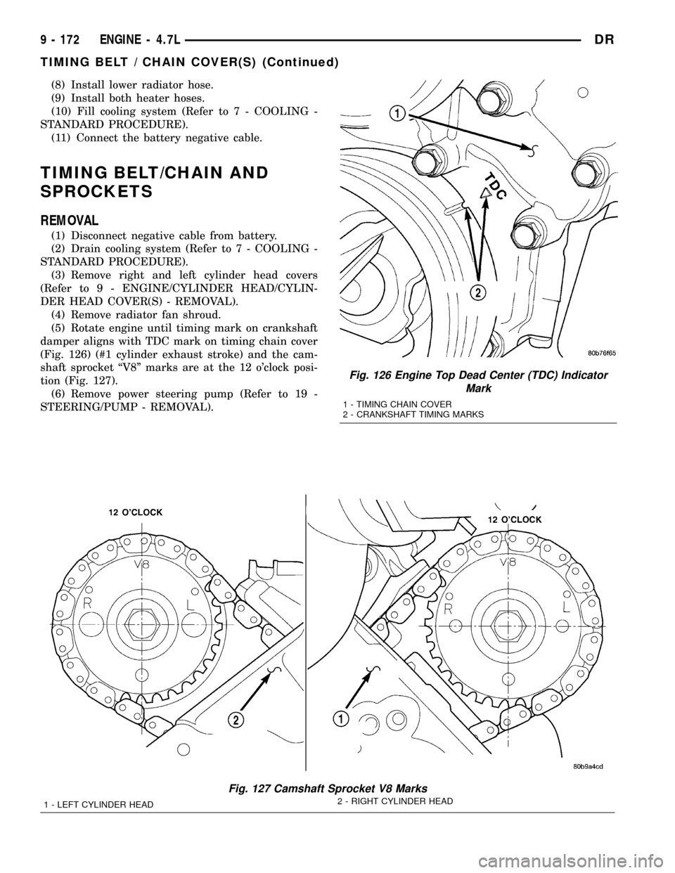
(5) Rotate engine until timing mark on crankshaft
damper aligns with TDC mark on timing chain cover
(Fig. 126) (#1 cylinder exhaust stroke) and the cam-
shaft sprocket ªV8º marks are at the 12 o'clock posi-
tion (Fig. 127).
(6) Remove power steering pump (Refer to 19 -
STEERING/PUMP - REMOVAL).
Fig. 126 Engine Top Dead Center (TDC) Indicator
Mark
1 - TIMING CHAIN COVER
2 - CRANKSHAFT TIMING MARKS
Fig. 127 Camshaft Sprocket V8 Marks
1 - LEFT CYLINDER HEAD2 - RIGHT CYLINDER HEAD
9 - 172 ENGINE - 4.7LDR
TIMING BELT / CHAIN COVER(S) (Continued)
Page 1414 of 2627
(6) Remove the viscous fan/drive (Refer to 7 -
COOLING/ENGINE/RADIATOR FAN - REMOVAL).
(7) Remove radiator (Refer to 7 - COOLING/EN-
GINE/RADIATOR - REMOVAL).
(8) Remove the upper crossmember and top core
support.
NOTE: It is not necessary to drain A/C system for
engine removal.
(9) Remove the A/C compressor with the lines
attached. Secure compressor out of the way.
(10) Remove generator assembly (Refer to 8 -
ELECTRICAL/CHARGING/GENERATOR -
REMOVAL).
(11) Remove the intake manifold and IAFM as an
assembly(Refer to 9 - ENGINE/MANIFOLDS/IN-
TAKE MANIFOLD - REMOVAL).
(12) Disconnect the heater hoses.
NOTE: It is not necessary to disconnect P/S hoses
from pump, for P/S pump removal.
(13) Remove the power steering pump and set
aside.
(14) Disconnect the fuel supply line (Refer to 14 -
FUEL SYSTEM/FUEL DELIVERY/QUICK CON-
NECT FITTING - STANDARD PROCEDURE).
(15) Raise and support the vehicle on a hoist and
drain the engine oil.
(16) Remove engine front mount thru-bolt nuts.
(17) Remove right side axle retaining bolts.
(18) Disconnect the transmission oil cooler lines
from their retainers at the oil pan bolts.
(19) Disconnect exhaust pipe at manifolds.
(20) Disconnect the starter wires. Remove starter
motor (Refer to 8 - ELECTRICAL/STARTING/
STARTER MOTOR - REMOVAL).
(21) Remove the structural dust cover and trans-
mission inspection cover,(Refer to 9 - ENGINE/EN-
GINE BLOCK/STRUCTURAL COVER - REMOVAL).
(22) Remove drive plate to converter bolts (Auto-
matic transmission equipped vehicles).
(23) Remove transmission bell housing to engine
block bolts.
(24) Lower the vehicle.
(25) Install engine lift fixture, special tool # 8984.
(26) Separate engine from transmission, remove
engine from vehicle, and install engine assembly on a
repair stand.
INSTALLATION
(1) Install engine lift fixture Special tool # 8984.
(2) Position the engine in the engine compartment.
(3) Lower engine into compartment and align
engine with transmission:²Manual Transmission: Align clutch disc assem-
bly (if disturbed). Install transmission input shaft
into clutch disc while mating engine and transmis-
sion surfaces. Install two transmission to engine
block mounting bolts finger tight.
²Automatic Transmission: Mate engine and trans-
mission and install two transmission to engine block
mounting bolts finger tight.
(4) Position the thru-bolt into the support cushion
brackets.
(5) Lower engine assembly until engine mount
through bolts rest in mount perches.
(6) Install remaining transmission to engine block
mounting bolts and tighten.
(7) Tighten engine mount through bolts.
(8) Install drive plate to torque converter bolts.
(Automatic transmission models)
(9) Install the structural dust cover and transmis-
sion dust cover,(Refer to 9 - ENGINE/ENGINE
BLOCK/STRUCTURAL COVER - INSTALLATION).
(10) Install the starter and connect the starter
wires (Refer to 8 - ELECTRICAL/STARTING/
STARTER MOTOR - INSTALLATION).
(11) Install exhaust pipe to manifold.
(12) Lower the vehicle.
(13) Remove engine lift fixture, special tool # 8984.
(14) Connect the fuel supply line (Refer to 14 -
FUEL SYSTEM/FUEL DELIVERY/QUICK CON-
NECT FITTING - STANDARD PROCEDURE).
(15) Reinstall the power steering pump.
(16) Connect the heater hoses.
(17) Install the intake manifold.
(18) Using a new gasket, install throttle body
(Refer to 14 - FUEL SYSTEM/FUEL INJECTION/
THROTTLE BODY - INSTALLATION).
(19) Install the generator and wire connections
(Refer to 8 - ELECTRICAL/CHARGING/GENERA-
TOR - INSTALLATION).
(20) Install a/c compressor and lines (Refer to 24 -
HEATING & AIR CONDITIONING/PLUMBING/A/C
COMPRESSOR - INSTALLATION).
(21) Install the accessory drive belt (Refer to 7 -
COOLING/ACCESSORY DRIVE/DRIVE BELTS -
INSTALLATION).
(22) Install upper radiator support crossmember.
(23) Install radiator (Refer to 7 - COOLING/EN-
GINE/RADIATOR - INSTALLATION).
(24) Connect the radiator lower hose.
(25) Connect the transmission oil cooler lines to
the radiator.
(26) Install the fan shroud.
(27) Install the fan (Refer to 7 - COOLING/EN-
GINE/RADIATOR FAN - INSTALLATION).
(28) Connect the radiator upper hose.
(29) Install the washer bottle.
(30) Connect the transmission cooler lines.
DRENGINE - 5.7L 9 - 191
ENGINE - 5.7L (Continued)
Page 1450 of 2627
INSPECTION
Inspect manifold for cracks.
Inspect mating surfaces of manifold for flatness
with a straight edge. Gasket surfaces must be flat
within 0.2 mm per 300 mm (0.008 inch per foot).
INSTALLATION
EXHAUST MANIFOLD
(1) Install manifold gasket and manifold.
(2) Install manifold bolts and tighten to 25 N´m
(18 ft. lbs.).
(3) Install heat shield and tighten nuts to 15 N´m
(11 ft. lbs.).
(4) Lower engine.
CAUTION: Do not damage engine harness while
lowering the engine.
(5) Remove engine support fixture from engine.
(6) Raise vehicle.
(7) Tighten right and left side engine mount
through bolts.
(8) Install exhaust flange to pipe bolts.
(9) Lower vehicle.
(10) Connect negative battery cable.
TIMING/CHAIN COVER
REMOVAL
(1) Disconnect the battery negative cable.
(2) Remove air cleaner assembly.
(3) Drain cooling system.
(4) Remove accessory drive belt.
(5) Remove fan and fan drive assembly (Refer to 7
- COOLING/ENGINE/FAN DRIVE VISCOUS
CLUTCH - REMOVAL).
(6) Remove coolant bottle and washer bottle.
(7) Remove fan shroud.
NOTE: It is not necessary to disconnect A/C lines or
discharge freon.
(8) Remove A/C compressor and set aside.
(9) Remove the generator.
(10) Remove upper radiator hose.
(11) Disconnect both heater hoses at timing cover.
(12) Disconnect lower radiator hose at engine.
(13) Remove accessory drive belt tensioner and
both idler pulleys.
(14) Remove crankshaft damper(Refer to 9 -
ENGINE/ENGINE BLOCK/VIBRATION DAMPER -
REMOVAL).NOTE: Do not remove the hoses from the power
steering pump.
(15) Remove power steering pump and set aside.
(16) Remove the dipstick support bolt.
(17) Drain the engine oil.
(18) Remove the oil pan and pick up tube(Refer to
9 - ENGINE/LUBRICATION/OIL PAN - REMOVAL).
NOTE: It is not necessary to remove water pump for
timing cover removal.
(19) Remove timing cover bolts and remove cover.
INSTALLATION
(1) Clean timing chain cover and block surface.
NOTE: Always install a new gasket on timing cover.
(2) Install cover and new gasket. Tighten fasteners
to 28 N´m (250 in. lbs.).
NOTE: The large lifting stud is torqued to 55 N´m
(40 ft. lbs.).
(3) Install the oil pan and pick up tube(Refer to 9 -
ENGINE/LUBRICATION/OIL PAN - INSTALLA-
TION).
(4) Install the A/C compressor.
(5) Install the generator.
(6) Install power steering pump.
(7) Install the dipstick support bolt.
(8) Install the thermostat housing.
(9) Install crankshaft damper(Refer to 9 -
ENGINE/ENGINE BLOCK/VIBRATION DAMPER -
INSTALLATION).
(10) Install accessory drive belt tensioner assembly
and both idler pulleys.
(11) Install radiator lower hose.
(12) Install both heater hoses.
(13) Install radiator fan shroud.
(14) Install the fan and fan drive assembly
(15) Install the accessory drive belt.
(16) Install the coolant bottle and washer bottle.
(17) Install the upper radiator hose.
(18) Install the air cleaner assembly.
(19) Fill cooling system.
(20) Refill engine oil.
(21) Connect the battery negative cable.
DRENGINE - 5.7L 9 - 227
EXHAUST MANIFOLD (Continued)
Page 1464 of 2627
(10) Drain engine oil. Remove and discard the oil
filter (Refer to 9 - ENGINE/LUBRICATION/OIL FIL-
TER - REMOVAL).
(11) Install the drain plug. Tighten the plug to 50
N´m (37 ft. lbs.) torque.
(12) Install a new oil filter (Refer to 9 - ENGINE/
LUBRICATION/OIL FILTER - INSTALLATION).
(13) Fill engine crankcase with the specified
amount and grade of oil (Refer to LUBRICATION &
MAINTENANCE/FLUID TYPES - SPECIFICA-
TIONS).
(14) Connect the negative cable(s) to the battery.
(15) Start the engine and check for any leaks.
REMOVAL
REMOVAL - ENGINE
(1) Disconnect both battery negative cables.
(2) Disconnect engine grid heater harness at grid
heater relays.
(3) Disconnect electrical connections from rear of
alternator.
(4) Recover A/C refrigerant. (Refer to 24 - HEAT-
ING & AIR CONDITIONING/PLUMBING - STAN-
DARD PROCEDURE).
(5) Raise vehicle on a hoist.
(6) Drain engine coolant (Refer to 7 - COOLING -
STANDARD PROCEDURE).
(7) Remove engine oil drain plug and drain engine
oil.
(8) Reinstall drain plug. Tighten to 50N´m (37 ft.
lbs.) torque.
(9) Lower the vehicle.
(10) Remove fan/drive assembly. Refer to Section 7
± Fan/Drive Removal
(11) Remove radiator upper hose.
(12) Remove upper fan shroud mounting bolts.
(13) Disconnect the coolant recovery bottle hose
from the radiator fill neck and remove bottle.
(14) Using a 36mm wrench, remove viscous fan/
drive assembly. (Refer to 7 - COOLING/ENGINE/RA-
DIATOR FAN - REMOVAL).
(15) Remove cooling fan and shroud together.
(16) Disconnect heater core supply and return
hoses from the cylinder head fitting and coolant pipe.
(17) Raise vehicle on a hoist.
(18) Remove transmission and transfer case (if
equipped).
(19) Disconnect exhaust pipe from turbocharger
extension pipe.
(20) Disconnect engine harness to vehicle harness
connectors.
(21) Remove starter motor (Refer to 8 - ELECTRI-
CAL/STARTING/STARTER MOTOR - REMOVAL).(22) Remove flywheel/flexplate.
(23) Remove transmission adapter
(24) Disconnect A/C suction/discharge hose from
the rear of the A/C compressor.
(25) Lower vehicle.
(26) Disconnect lower radiator hose from radiator
outlet.
(27) Automatic transmission models:
(28) Disconnect transmission oil cooler lines from
in front of radiator using special tool #6931
(29) Remove radiator. (Refer to 7 - COOLING/EN-
GINE/RADIATOR - REMOVAL).
(30) If A/C equipped, disconnect A/C condenser
refrigerant lines.
(31) Disconnect charge air cooler piping.
(32) Remove charge air cooler mounting bolts.
(33) Remove charge air cooler (and A/C condenser
if equipped) from vehicle.
(34) Remove damper and speed indicator ring from
front of engine.
(35) Disconnect engine block heater connector.
(36) Disconnect A/C compressor and pressure sen-
sor electrical connectors.
(37) Remove the passenger battery ground cable
from the engine block. Remove the driver side bat-
tery ground cable from the engine block.
(38) Remove power steering pump from engine by
removing 3 bolts.
(39) Remove accelerator linkage cover.
(40) Disconnect cables from on-engine APPS.
(41) Disconnect the ECM power connector.
(42) Disconnect the ECM ground wire from the
hydroform screw.
(43) Disconnect the fuel supply and return hoses.
(44) Remove the cylinder head cover. (Refer to 9 -
ENGINE/CYLINDER HEAD/CYLINDER HEAD
COVER(S) - REMOVAL).
(45) Disconnect the 3 injector harness connectors
at the rocker housing. Disconnect the wire harnesses
from the injectors.
(46) Remove the rear engine lift bracket.
(47) Remove cylinder #4, #5, and #6 intake and
exhaust rocker arms, pedestals, and push tubes. Note
the original location for re-assembly.
(48) Loosen #6 fuel line shield bolts and rotate
shield out of the way.
(49) Remove cylinder #5 and #6 high pressure fuel
lines. Remove the fuel connector tube nut and fuel
connector tube. Remove cylinder #5 and #6 fuel injec-
tor.
(50) Remove rocker housing.
DRENGINE 5.9L DIESEL 9 - 241
ENGINE 5.9L DIESEL (Continued)