1998 DODGE RAM 1500 Cargo
[x] Cancel search: CargoPage 1156 of 2627
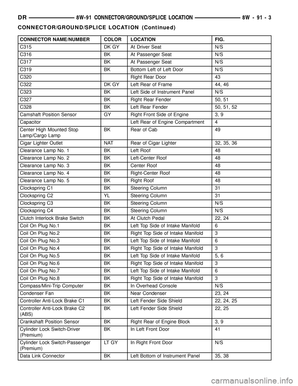
CONNECTOR NAME/NUMBER COLOR LOCATION FIG.
C315 DK GY At Driver Seat N/S
C316 BK At Passenger Seat N/S
C317 BK At Passenger Seat N/S
C319 BK Bottom Left of Left Door N/S
C320 Right Rear Door 43
C322 DK GY Left Rear of Frame 44, 46
C323 BK Left Side of Instrument Panel N/S
C327 BK Right Rear Fender 50, 51
C328 BK Left Rear Fender 50, 51, 52
Camshaft Position Sensor GY Right Front Side of Engine 3, 9
Capacitor Left Rear of Engine Compartment 4
Center High Mounted Stop
Lamp/Cargo LampBK Rear of Cab 49
Cigar Lighter Outlet NAT Rear of Cigar Lighter 32, 35, 36
Clearance Lamp No. 1 BK Left Roof 48
Clearance Lamp No. 2 BK Left-Center Roof 48
Clearance Lamp No. 3 BK Center Roof 48
Clearance Lamp No. 4 BK Right-Center Roof 48
Clearance Lamp No. 5 BK Right Roof 48
Clockspring C1 BK Steering Column 31
Clockspring C2 YL Steering Column 31
Clockspring C3 BK Steering Column N/S
Clockspring C4 BK Steering Column N/S
Clutch Interlock Brake Switch BK At Clutch Pedal 22, 24
Coil On Plug No.1 BK Left Top Side of Intake Manifold 6
Coil On Plug No.2 BK Right Top Side of Intake Manifold 3
Coil On Plug No.3 BK Left Top Side of Intake Manifold 6
Coil On Plug No.4 BK Right Top Side of Intake Manifold 3
Coil On Plug No.5 BK Left Top Side of Intake Manifold 5, 6
Coil On Plug No.6 BK Right Top Side of Intake Manifold 3
Coil On Plug No.7 BK Left Top Side of Intake Manifold 6
Coil On Plug No.8 BK Right Top Side of Intake Manifold 3
Compass/Mini-Trip Computer BK In Overhead Console N/S
Condenser Fan BK Near Condenser 23, 24
Controller Anti-Lock Brake C1 BK Left Fender Side Shield 22, 24, 25
Controller Anti-Lock Brake C2
(ABS)BK Left Fender Side Shield 22, 25
Crankshaft Position Sensor BK Right Rear of Engine Block 3, 9
Cylinder Lock Switch-Driver
(Premium)BK In Left Front Door 41
Cylinder Lock Switch-Passenger
(Premium)LT GY In Right Front Door N/S
Data Link Connector BK Left Bottom of Instrument Panel 35, 38
DR8W-91 CONNECTOR/GROUND/SPLICE LOCATION 8W - 91 - 3
CONNECTOR/GROUND/SPLICE LOCATION (Continued)
Page 1538 of 2627
OPERATION
Exhaust gas pressure and energy drive the tur-
bine, which in turn drives a centrifugal compressor
that compresses the inlet air, and forces the air into
the engine through the charge air cooler and plumb-
ing. Since heat is a by-product of this compression,
the air must pass through a charge air cooler to cool
the incoming air and maintain power and efficiency.
Increasing air flow to the engine provides:
²Improved engine performance
²Lower exhaust smoke density
²Improved operating economy
²Altitude compensation
²Noise reduction.
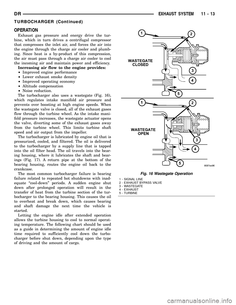
The turbocharger also uses a wastegate (Fig. 16),
which regulates intake manifold air pressure and
prevents over boosting at high engine speeds. When
the wastegate valve is closed, all of the exhaust gases
flow through the turbine wheel. As the intake mani-
fold pressure increases, the wastegate actuator opens
the valve, diverting some of the exhaust gases away
from the turbine wheel. This limits turbine shaft
speed and air output from the impeller.
The turbocharger is lubricated by engine oil that is
pressurized, cooled, and filtered. The oil is delivered
to the turbocharger by a supply line that is tapped
into the oil filter head. The oil travels into the bear-
ing housing, where it lubricates the shaft and bear-
ings (Fig. 17). A return pipe at the bottom of the
bearing housing, routes the engine oil back to the
crankcase.
The most common turbocharger failure is bearing
failure related to repeated hot shutdowns with inad-
equate ªcool-downº periods. A sudden engine shut
down after prolonged operation will result in the
transfer of heat from the turbine section of the tur-
bocharger to the bearing housing. This causes the oil
to overheat and break down, which causes bearing
and shaft damage the next time the vehicle is
started.
Letting the engine idle after extended operation
allows the turbine housing to cool to normal operat-
ing temperature. The following chart should be used
as a guide in determining the amount of engine idle
time required to sufficiently cool down the turbo-
charger before shut down, depending upon the type
of driving and the amount of cargo.
Fig. 16 Wastegate Operation
1 - SIGNAL LINE
2 - EXHAUST BYPASS VALVE
3 - WASTEGATE
4 - EXHAUST
5 - TURBINE
DREXHAUST SYSTEM 11 - 13
TURBOCHARGER (Continued)
Page 1556 of 2627
STANDARD PROCEDURE - REAR FRAME
H-SECTION REPLACEMENT
CAUTION: This procedure is designed to replace
the H-section/spare tire support located at the rear
of the frame assembly. Prior to any cutting, the
vehicle must be mounted on the appropriate frame
repair equipment (ªframe rackº), checked with three
dimensional measuring equipment, and the neces-
sary pull corrections made. If damage remains in
the frame beyond the area covered by this service
part after the pull, the frame must be replaced in its
entirety.
(1) Before proceding with this repair procedure
review the required service warnings and precau-
tions. (Refer to 13 - FRAME & BUMPERS/FRAME -
WARNING)
(2) Disconnect and isolate the battery negative
cable.
(3) Remove the cargo box. (Refer to 23 - BODY/EX-
TERIOR/CARGO BOX - REMOVAL)
(4) Remove the trailer hitch. (Refer to 13 - FRAME
& BUMPERS/FRAME/TRAILER HITCH -
REMOVAL)
(5) Raise and support the frame so the tires are off
floor.(6) Remove the shock absorbers. (Refer to 2 - SUS-
PENSION/REAR/SHOCK - REMOVAL)
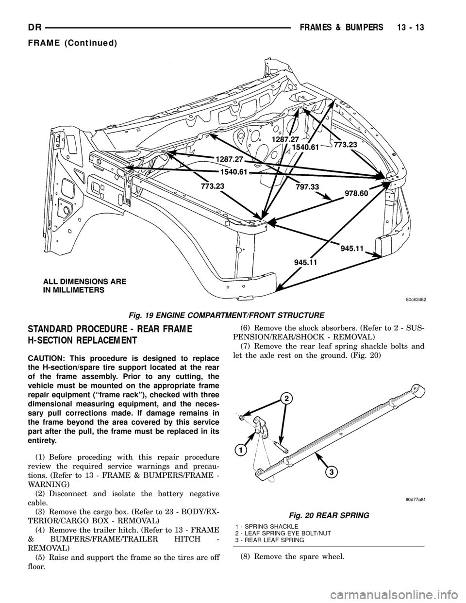
(7) Remove the rear leaf spring shackle bolts and
let the axle rest on the ground. (Fig. 20)
(8) Remove the spare wheel.
Fig. 19 ENGINE COMPARTMENT/FRONT STRUCTURE
Fig. 20 REAR SPRING
1 - SPRING SHACKLE
2 - LEAF SPRING EYE BOLT/NUT
3 - REAR LEAF SPRING
DRFRAMES & BUMPERS 13 - 13
FRAME (Continued)
Page 1558 of 2627
(26) Install the lower shock absorber bolts. (Refer
to 2 - SUSPENSION/REAR/SHOCK - INSTALLA-
TION)
(27) Install the trailer hitch. (Refer to 13 - FRAME
& BUMPERS/FRAME/TRAILER HITCH - INSTAL-
LATION)(28) Install the cargo box. (Refer to 23 - BODY/EX-
TERIOR/CARGO BOX - INSTALLATION)
(29) Reconnect the battery ground.
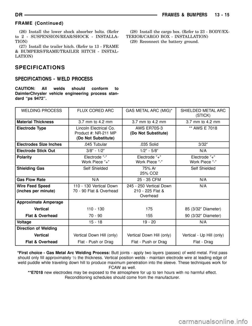
SPECIFICATIONS
SPECIFICATIONS - WELD PROCESS
CAUTION: All welds should conform to
DaimlerChrysler vehicle engineering process stan-
dard ªps 9472º.
WELDING PROCESS FLUX CORED ARC GAS METAL ARC (MIG)* SHIELDED METAL ARC
(STICK)
Material Thickness3.7 mm to 4.2 mm 3.7 mm to 4.2 mm 3.7 mm to 4.2 mm
Electrode TypeLincoln Electrical Co.
Product #: NR-211 MP
(Do Not Substitute)AWS ER70S-3
(Do Not Substitute)** AWS E 7018
Electrodes Size Inches.045 Tubular .035 Solid 3/329
Electrode Stick Out3/89- 1/291/29- 5/89N/A
PolarityElectrode9-9
Work Piece9+9Electrode9+9
Work Piece9-9Electrode9+9
Work Piece9-9
Shielding GasSelf Shielded 75% Ar
25% CO2Self Shielded
Gas Flow RateN/A 25 - 35 CFM N/A
Wire Feed Speed
(inches per minute)110 - 130 Vertical Down
70 - 90 Flat & Overhead245 - 250 Vertical Down
210 - 225 Flat &
OverheadN/A
Approximate Amperage
Vertical110 - 130 175 85 (3/329Diameter)
Flat & Overhead70 - 90 155 90 (3/329Diameter)
Voltage15-18 19-20 N/A
Direction of Welding
VerticalVertical Down Hill (only) Vertical Down Hill (only) Vertical - Up Hill (only)
Flat & OverheadFlat - Push or Drag Flat - Push or Drag Flat - Drag
*First choice - Gas Metal Arc Welding Process:Butt joints - apply two layers (passes) of weld metal. First pass
should only fill approximately
1¤2the thickness. Vertical position welds - maintain electrode wire at leading edge of
weld puddle while traveling down hill to produce maximum penetration into the sleeve. These techniques work for
FCAW as well.
**E7018new electrodes may be exposed to the atmosphere for up to ten hours with no harmful effect.
Reconditioning schedules should come from the manufacturer.
DRFRAMES & BUMPERS 13 - 15
FRAME (Continued)
Page 1565 of 2627
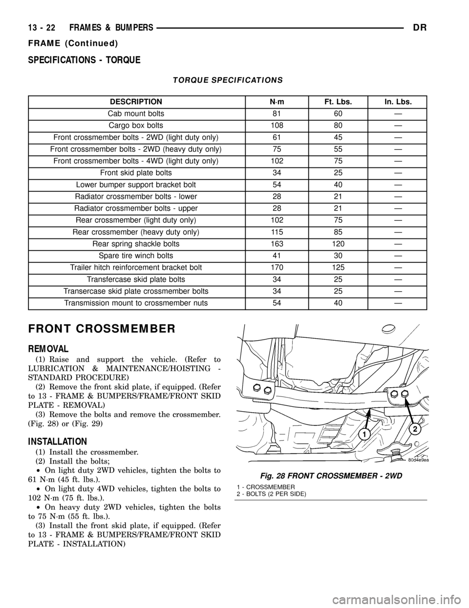
SPECIFICATIONS - TORQUE
TORQUE SPECIFICATIONS
DESCRIPTION N´m Ft. Lbs. In. Lbs.
Cab mount bolts 81 60 Ð
Cargo box bolts 108 80 Ð
Front crossmember bolts - 2WD (light duty only) 61 45 Ð
Front crossmember bolts - 2WD (heavy duty only) 75 55 Ð
Front crossmember bolts - 4WD (light duty only) 102 75 Ð
Front skid plate bolts 34 25 Ð
Lower bumper support bracket bolt 54 40 Ð
Radiator crossmember bolts - lower 28 21 Ð
Radiator crossmember bolts - upper 28 21 Ð
Rear crossmember (light duty only) 102 75 Ð
Rear crossmember (heavy duty only) 115 85 Ð
Rear spring shackle bolts 163 120 Ð
Spare tire winch bolts 41 30 Ð
Trailer hitch reinforcement bracket bolt 170 125 Ð
Transfercase skid plate bolts 34 25 Ð
Transercase skid plate crossmember bolts 34 25 Ð
Transmission mount to crossmember nuts 54 40 Ð
FRONT CROSSMEMBER
REMOVAL
(1) Raise and support the vehicle. (Refer to
LUBRICATION & MAINTENANCE/HOISTING -
STANDARD PROCEDURE)
(2) Remove the front skid plate, if equipped. (Refer
to 13 - FRAME & BUMPERS/FRAME/FRONT SKID
PLATE - REMOVAL)
(3) Remove the bolts and remove the crossmember.
(Fig. 28) or (Fig. 29)
INSTALLATION
(1) Install the crossmember.
(2) Install the bolts;
²On light duty 2WD vehicles, tighten the bolts to
61 N´m (45 ft. lbs.).
²On light duty 4WD vehicles, tighten the bolts to
102 N´m (75 ft. lbs.).
²On heavy duty 2WD vehicles, tighten the bolts
to 75 N´m (55 ft. lbs.).
(3) Install the front skid plate, if equipped. (Refer
to 13 - FRAME & BUMPERS/FRAME/FRONT SKID
PLATE - INSTALLATION)
Fig. 28 FRONT CROSSMEMBER - 2WD
1 - CROSSMEMBER
2 - BOLTS (2 PER SIDE)
13 - 22 FRAMES & BUMPERSDR
FRAME (Continued)
Page 1568 of 2627
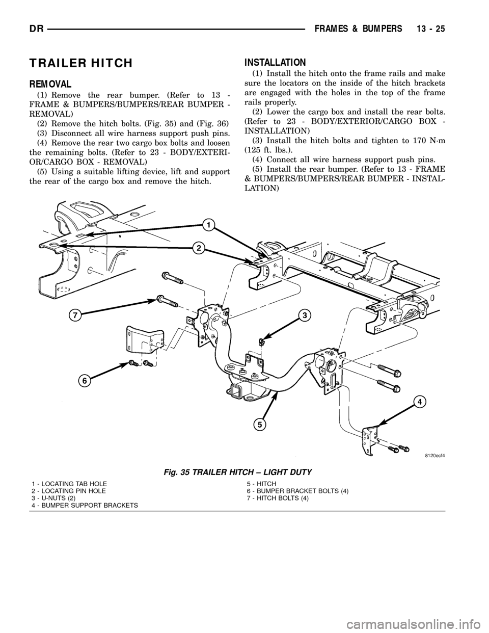
TRAILER HITCH
REMOVAL
(1) Remove the rear bumper. (Refer to 13 -
FRAME & BUMPERS/BUMPERS/REAR BUMPER -
REMOVAL)
(2) Remove the hitch bolts. (Fig. 35) and (Fig. 36)
(3) Disconnect all wire harness support push pins.
(4) Remove the rear two cargo box bolts and loosen
the remaining bolts. (Refer to 23 - BODY/EXTERI-
OR/CARGO BOX - REMOVAL)
(5) Using a suitable lifting device, lift and support
the rear of the cargo box and remove the hitch.
INSTALLATION
(1) Install the hitch onto the frame rails and make
sure the locators on the inside of the hitch brackets
are engaged with the holes in the top of the frame
rails properly.
(2) Lower the cargo box and install the rear bolts.
(Refer to 23 - BODY/EXTERIOR/CARGO BOX -
INSTALLATION)
(3) Install the hitch bolts and tighten to 170 N´m
(125 ft. lbs.).
(4) Connect all wire harness support push pins.
(5) Install the rear bumper. (Refer to 13 - FRAME
& BUMPERS/BUMPERS/REAR BUMPER - INSTAL-
LATION)
Fig. 35 TRAILER HITCH ± LIGHT DUTY
1 - LOCATING TAB HOLE
2 - LOCATING PIN HOLE
3 - U-NUTS (2)
4 - BUMPER SUPPORT BRACKETS5 - HITCH
6 - BUMPER BRACKET BOLTS (4)
7 - HITCH BOLTS (4)
DRFRAMES & BUMPERS 13 - 25
Page 2307 of 2627
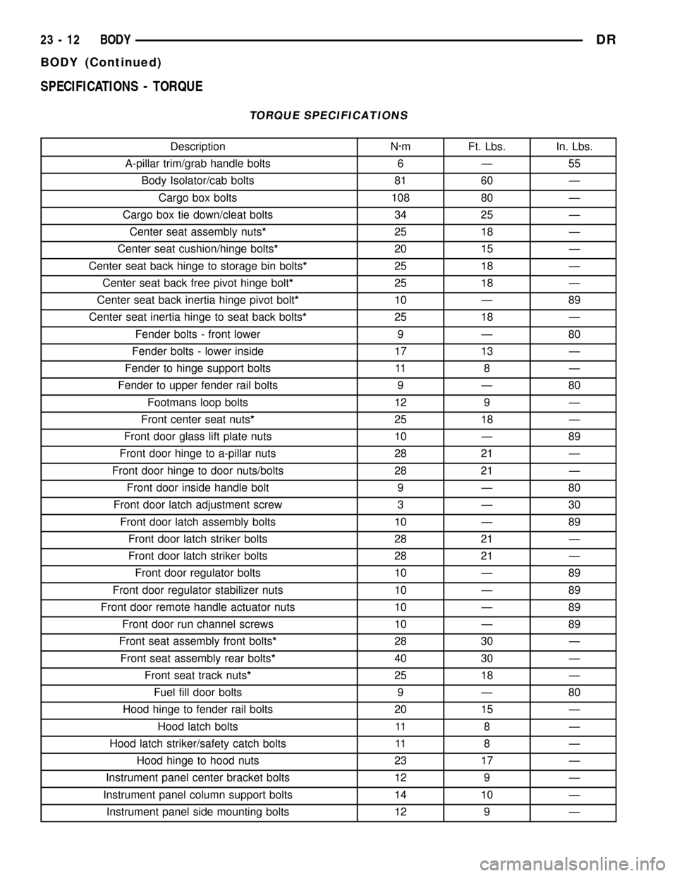
SPECIFICATIONS - TORQUE
TORQUE SPECIFICATIONS
Description N´m Ft. Lbs. In. Lbs.
A-pillar trim/grab handle bolts 6 Ð 55
Body Isolator/cab bolts 81 60 Ð
Cargo box bolts 108 80 Ð
Cargo box tie down/cleat bolts 34 25 Ð
Center seat assembly nuts*25 18 Ð
Center seat cushion/hinge bolts*20 15 Ð
Center seat back hinge to storage bin bolts*25 18 Ð
Center seat back free pivot hinge bolt*25 18 Ð
Center seat back inertia hinge pivot bolt*10 Ð 89
Center seat inertia hinge to seat back bolts*25 18 Ð
Fender bolts - front lower 9 Ð 80
Fender bolts - lower inside 17 13 Ð
Fender to hinge support bolts 11 8 Ð
Fender to upper fender rail bolts 9 Ð 80
Footmans loop bolts 12 9 Ð
Front center seat nuts*25 18 Ð
Front door glass lift plate nuts 10 Ð 89
Front door hinge to a-pillar nuts 28 21 Ð
Front door hinge to door nuts/bolts 28 21 Ð
Front door inside handle bolt 9 Ð 80
Front door latch adjustment screw 3 Ð 30
Front door latch assembly bolts 10 Ð 89
Front door latch striker bolts 28 21 Ð
Front door latch striker bolts 28 21 Ð
Front door regulator bolts 10 Ð 89
Front door regulator stabilizer nuts 10 Ð 89
Front door remote handle actuator nuts 10 Ð 89
Front door run channel screws 10 Ð 89
Front seat assembly front bolts*28 30 Ð
Front seat assembly rear bolts*40 30 Ð
Front seat track nuts*25 18 Ð
Fuel fill door bolts 9 Ð 80
Hood hinge to fender rail bolts 20 15 Ð
Hood latch bolts 11 8 Ð
Hood latch striker/safety catch bolts 11 8 Ð
Hood hinge to hood nuts 23 17 Ð
Instrument panel center bracket bolts 12 9 Ð
Instrument panel column support bolts 14 10 Ð
Instrument panel side mounting bolts 12 9 Ð
23 - 12 BODYDR
BODY (Continued)
Page 2310 of 2627
TAILGATE
TABLE OF CONTENTS
page page
CHECK CABLE
REMOVAL.............................15
INSTALLATION.........................15
COVER
REMOVAL.............................16
INSTALLATION.........................16
HINGE
REMOVAL.............................16
INSTALLATION.........................16
LATCH
REMOVAL.............................16INSTALLATION.........................16
LATCH STRIKER
REMOVAL.............................16
INSTALLATION.........................17
RELEASE HANDLE/LATCH REMOTE
REMOVAL.............................17
INSTALLATION.........................17
TAILGATE
REMOVAL.............................17
INSTALLATION.........................17
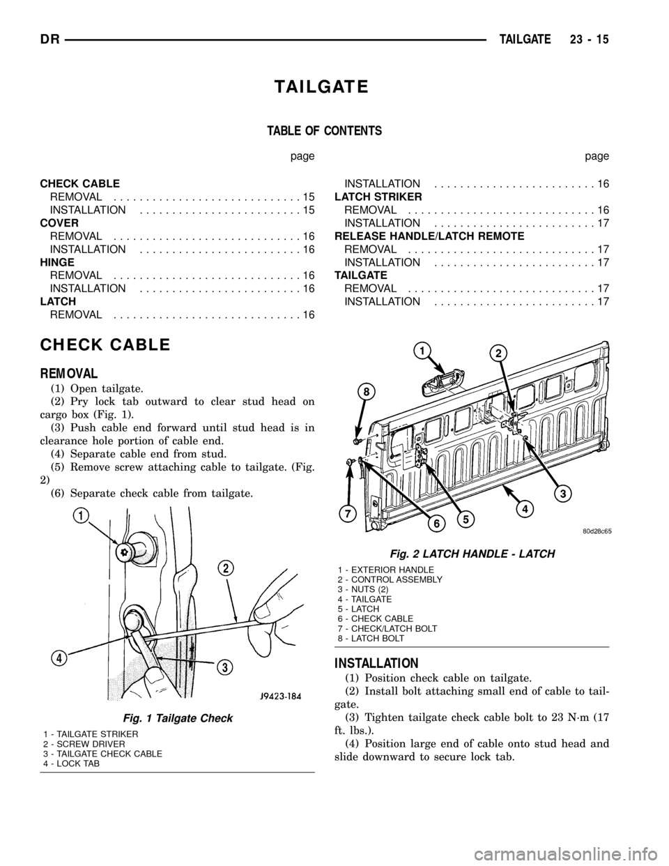
CHECK CABLE
REMOVAL
(1) Open tailgate.
(2) Pry lock tab outward to clear stud head on
cargo box (Fig. 1).
(3) Push cable end forward until stud head is in
clearance hole portion of cable end.
(4) Separate cable end from stud.
(5) Remove screw attaching cable to tailgate. (Fig.
2)
(6) Separate check cable from tailgate.
INSTALLATION
(1) Position check cable on tailgate.
(2) Install bolt attaching small end of cable to tail-
gate.
(3) Tighten tailgate check cable bolt to 23 N´m (17
ft. lbs.).
(4) Position large end of cable onto stud head and
slide downward to secure lock tab.
Fig. 1 Tailgate Check
1 - TAILGATE STRIKER
2 - SCREW DRIVER
3 - TAILGATE CHECK CABLE
4 - LOCK TAB
Fig. 2 LATCH HANDLE - LATCH
1 - EXTERIOR HANDLE
2 - CONTROL ASSEMBLY
3 - NUTS (2)
4 - TAILGATE
5-LATCH
6 - CHECK CABLE
7 - CHECK/LATCH BOLT
8 - LATCH BOLT
DRTAILGATE 23 - 15