1998 DODGE RAM 1500 lock
[x] Cancel search: lockPage 1267 of 2627
CRANKSHAFT MAIN
BEARINGS
STANDARD PROCEDURE
MAIN BEARING FITTING
SELECT FIT IDENTIFICATION
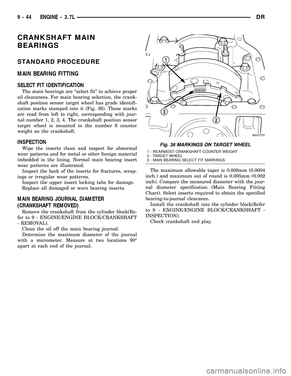
The main bearings are ªselect fitº to achieve proper
oil clearances. For main bearing selection, the crank-
shaft position sensor target wheel has grade identifi-
cation marks stamped into it (Fig. 36). These marks
are read from left to right, corresponding with jour-
nal number 1, 2, 3, 4. The crankshaft position sensor
target wheel is mounted to the number 6 counter
weight on the crankshaft.
INSPECTION
Wipe the inserts clean and inspect for abnormal
wear patterns and for metal or other foreign material
imbedded in the lining. Normal main bearing insert
wear patterns are illustrated.
Inspect the back of the inserts for fractures, scrap-
ings or irregular wear patterns.
Inspect the upper insert locking tabs for damage.
Replace all damaged or worn bearing inserts.
MAIN BEARING JOURNAL DIAMETER
(CRANKSHAFT REMOVED)
Remove the crankshaft from the cylinder block(Re-
fer to 9 - ENGINE/ENGINE BLOCK/CRANKSHAFT
- REMOVAL).
Clean the oil off the main bearing journal.
Determine the maximum diameter of the journal
with a micrometer. Measure at two locations 90É
apart at each end of the journal.The maximum allowable taper is 0.008mm (0.0004
inch.) and maximum out of round is 0.005mm (0.002
inch). Compare the measured diameter with the jour-
nal diameter specification (Main Bearing Fitting
Chart). Select inserts required to obtain the specified
bearing-to-journal clearance.
Install the crankshaft into the cylinder block(Refer
to 9 - ENGINE/ENGINE BLOCK/CRANKSHAFT -
INSPECTION).
Check crankshaft end play.
Fig. 36 MARKINGS ON TARGET WHEEL
1 - REARMOST CRANKSHAFT COUNTER WEIGHT
2 - TARGET WHEEL
3 - MAIN BEARING SELECT FIT MARKINGS
9 - 44 ENGINE - 3.7LDR
Page 1269 of 2627
CRANKSHAFT OIL SEAL - FRONT
REMOVAL
(1) Disconnect negative cable from battery.
(2) Remove accessory drive belt (Refer to 7 -
COOLING/ACCESSORY DRIVE/DRIVE BELTS -
REMOVAL).
(3) Remove A/C compressor mouning fasteners and
set aside.
(4) Drain cooling system (Refer to 7 - COOLING -
STANDARD PROCEDURE).
(5) Remove upper radiator hose.
(6) Disconnect electrical connector for fan mounted
inside radiator shroud.
(7) Remove radiator shroud attaching fasteners.
NOTE: Transmission cooler line snaps into shroud
lower right hand corner.
(8)
Remove radiator cooling fan and shroud (Refer to
7 - COOLING/ENGINE/RADIATOR FAN - REMOVAL).
(9) Remove crankshaft damper bolt.
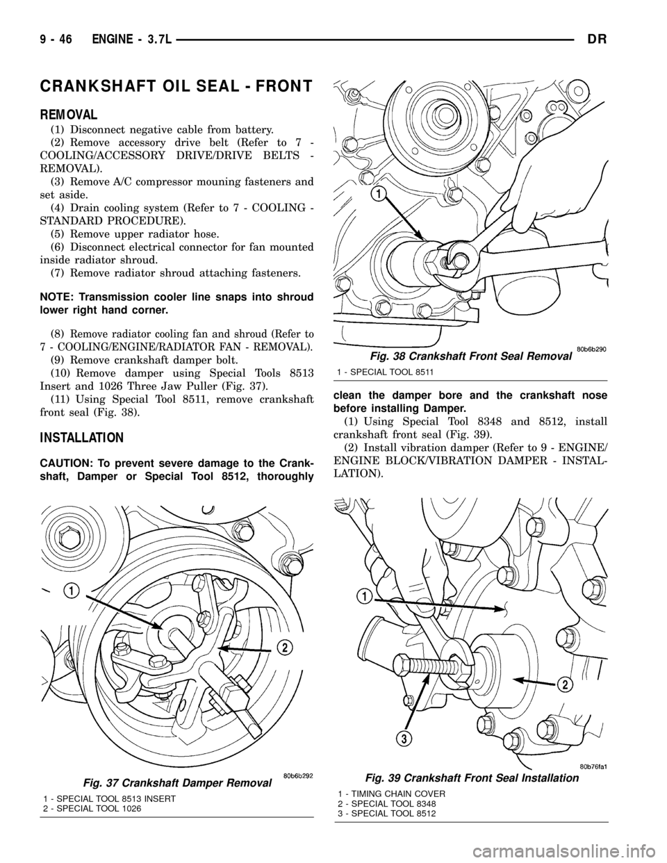
(10) Remove damper using Special Tools 8513
Insert and 1026 Three Jaw Puller (Fig. 37).
(11) Using Special Tool 8511, remove crankshaft
front seal (Fig. 38).
INSTALLATION
CAUTION: To prevent severe damage to the Crank-
shaft, Damper or Special Tool 8512, thoroughlyclean the damper bore and the crankshaft nose
before installing Damper.
(1) Using Special Tool 8348 and 8512, install
crankshaft front seal (Fig. 39).
(2) Install vibration damper (Refer to 9 - ENGINE/
ENGINE BLOCK/VIBRATION DAMPER - INSTAL-
LATION).
Fig. 37 Crankshaft Damper Removal
1 - SPECIAL TOOL 8513 INSERT
2 - SPECIAL TOOL 1026
Fig. 39 Crankshaft Front Seal Installation
1 - TIMING CHAIN COVER
2 - SPECIAL TOOL 8348
3 - SPECIAL TOOL 8512
Fig. 38 Crankshaft Front Seal Removal
1 - SPECIAL TOOL 8511
9 - 46 ENGINE - 3.7LDR
Page 1270 of 2627
(3) Install radiator cooling fan and shroud (Refer
to 7 - COOLING/ENGINE/RADIATOR FAN -
INSTALLATION).
(4) Install upper radiator hose.
(5) Install A/C compressor and tighten fasteners to
54 N´m (40 ft. lbs.).
(6) Install accessory drive belt refer (Refer to 7 -
COOLING/ACCESSORY DRIVE/DRIVE BELTS -
INSTALLATION).
(7) Refill cooling system (Refer to 7 - COOLING -
STANDARD PROCEDURE).
(8) Connect negative cable to battery.
CRANKSHAFT OIL SEAL -
REAR
REMOVAL
NOTE: This procedure can be performed in vehicle.
(1) If being preformed in vehicle, remove the
transmission.
(2) Remove the flexplate (Refer to 9 - ENGINE/
ENGINE BLOCK/FLEX PLATE - REMOVAL).
NOTE: The crankshaft oil seal CAN NOT be reused
after removal.
NOTE: The crankshaft rear oil seal remover Special
Tool 8506 must be installed deeply into the seal.
Continue to tighten the removal tool into the seal
until the tool can not be turned farther. Failure to
install tool correctly the first time will cause tool to
pull free of seal without removing seal from engine.
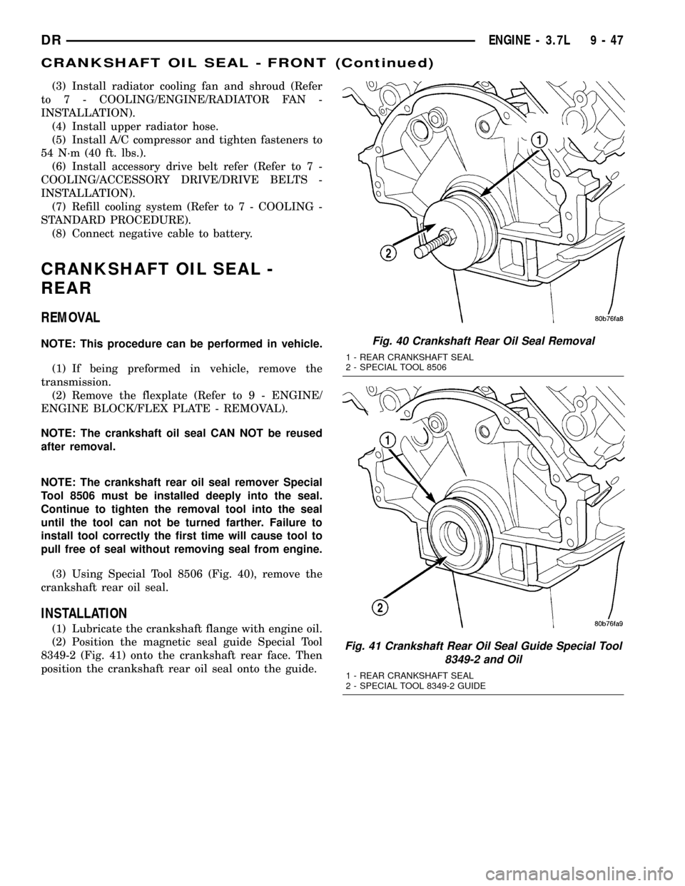
(3) Using Special Tool 8506 (Fig. 40), remove the
crankshaft rear oil seal.
INSTALLATION
(1) Lubricate the crankshaft flange with engine oil.
(2) Position the magnetic seal guide Special Tool
8349-2 (Fig. 41) onto the crankshaft rear face. Then
position the crankshaft rear oil seal onto the guide.
Fig. 40 Crankshaft Rear Oil Seal Removal
1 - REAR CRANKSHAFT SEAL
2 - SPECIAL TOOL 8506
Fig. 41 Crankshaft Rear Oil Seal Guide Special Tool
8349-2 and Oil
1 - REAR CRANKSHAFT SEAL
2 - SPECIAL TOOL 8349-2 GUIDE
DRENGINE - 3.7L 9 - 47
CRANKSHAFT OIL SEAL - FRONT (Continued)
Page 1271 of 2627
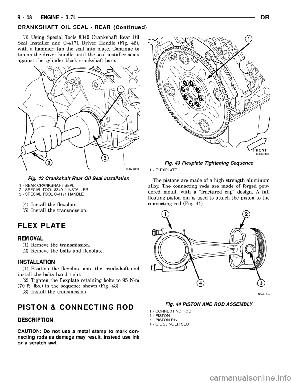
(3) Using Special Tools 8349 Crankshaft Rear Oil
Seal Installer and C-4171 Driver Handle (Fig. 42),
with a hammer, tap the seal into place. Continue to
tap on the driver handle until the seal installer seats
against the cylinder block crankshaft bore.
(4) Install the flexplate.
(5) Install the transmission.
FLEX PLATE
REMOVAL
(1) Remove the transmission.
(2) Remove the bolts and flexplate.
INSTALLATION
(1) Position the flexplate onto the crankshaft and
install the bolts hand tight.
(2) Tighten the flexplate retaining bolts to 95 N´m
(70 ft. lbs.) in the sequence shown (Fig. 43).
(3) Install the transmission.
PISTON & CONNECTING ROD
DESCRIPTION
CAUTION: Do not use a metal stamp to mark con-
necting rods as damage may result, instead use ink
or a scratch awl.The pistons are made of a high strength aluminum
alloy. The connecting rods are made of forged pow-
dered metal, with a ªfractured capº design. A full
floating piston pin is used to attach the piston to the
connecting rod (Fig. 44).
Fig. 42 Crankshaft Rear Oil Seal Installation
1 - REAR CRANKSHAFT SEAL
2 - SPECIAL TOOL 8349-1 INSTALLER
3 - SPECIAL TOOL C-4171 HANDLE
Fig. 43 Flexplate Tightening Sequence
1 - FLEXPLATE
Fig. 44 PISTON AND ROD ASSEMBLY
1 - CONNECTING ROD
2 - PISTON
3 - PISTON PIN
4 - OIL SLINGER SLOT
9 - 48 ENGINE - 3.7LDR
CRANKSHAFT OIL SEAL - REAR (Continued)
Page 1275 of 2627
²Timing chain cover (Refer to 9 - ENGINE/
VALVE TIMING/TIMING BELT / CHAIN COVER(S)
- REMOVAL).
²Cylinder head(s) (Refer to 9 - ENGINE/CYLIN-
DER HEAD - REMOVAL) and (Refer to 9 - ENGINE/
CYLINDER HEAD - REMOVAL).
(3) If necessary, remove top ridge of cylinder bores
with a reliable ridge reamer before removing pistons
from cylinder block.Be sure to keep tops of pis-
tons covered during this operation.Pistons and
connecting rods must be removed from top of cylinder
block. When removing piston and connecting rod
assemblies from the engine, rotate crankshaft so the
each connecting rod is centered in cylinder bore.
CAUTION: DO NOT use a number stamp or a punch
to mark connecting rods or caps, as damage to
connecting rods could occur
NOTE: Connecting rods and bearing caps are not
interchangeable and should be marked before
removing to ensure correct reassembly.
(4) Mark connecting rod and bearing cap positions
using a permanent ink marker or scribe tool.
CAUTION: Care must be taken not to damage the
fractured rod and cap joint face surfaces, as engine
damage may occur.
(5) Remove connecting rod cap. Install Special Tool
8507 Connecting Rod Guides into the connecting rod
being removed. Remove piston from cylinder bore.
Repeat this procedure for each piston being removed.
CAUTION: Care must be taken not to nick crank-
shaft journals, as engine damage may occur
(6) Immediately after piston and connecting rod
removal, install bearing cap on the mating connect-
ing rod to prevent damage to the fractured cap and
rod surfaces.
CLEANING
CAUTION: DO NOT use a wire wheel or other abra-
sive cleaning devise to clean the pistons or con-
necting rods. The pistons have a Moly coating, this
coating must not be damaged.
(1) Using a suitable cleaning solvent clean the pis-
tons in warm water and towel dry.
(2) Use a wood or plastic scraper to clean the ring
land grooves.
CAUTION: DO NOT remove the piston pin from the
piston and connecting rod assembly.
INSPECTION
Check the connecting rod journal for excessive
wear, taper and scoring (Refer to 9 - ENGINE/EN-
GINE BLOCK/CONNECTING ROD BEARINGS -
STANDARD PROCEDURE).
Check the connecting rod for signs of twist or bend-
ing.
Check the piston for taper and elliptical shape
before it is fitted into the cylinder bore (Refer to 9 -
ENGINE/ENGINE BLOCK/PISTON & CONNECT-
ING ROD - STANDARD PROCEDURE).
Check the piston for scoring, or scraping marks in
the piston skirts. Check the ring lands for cracks
and/or deterioration.
INSTALLATION
(1) Before installing piston and connecting rod
assemblies into the bore, install the piston rings.
(2) Immerse the piston head and rings in clean
engine oil. Position a ring compressor over the piston
and rings. Tighten ring compressor.Ensure posi-
tion of rings do not change during this opera-
tion.
(3) Position bearing onto connecting rod. Ensure
that hole in bearing shell aligns with hole in connect-
ing rod. Lubricate bearing surface with clean engine
oil.
(4) Install Special Tool 8507 Connecting Rod
Guides into connecting rod bolt threads (Fig. 53).
(5) The pistons are marked on the piston pin bore
surface with an raised ªFº indicating installation
position. This mark must be pointing toward the
front of engine on both cylinder banks. The connect-
ing rod oil slinger slot faces the front of the engine
(Fig. 54).
(6) Wipe cylinder bore clean and lubricate with
engine oil.
(7) Rotate crankshaft until connecting rod journal
is on the center of cylinder bore. Insert rod and pis-
ton into cylinder bore and carefully position connect-
ing rod guides over crankshaft journal.
(8) Tap piston down in cylinder bore using a ham-
mer handle. While at the same time, guide connect-
ing rod into position on rod journal.
CAUTION: Connecting Rod Bolts are Torque to
Yield Bolts and Must Not Be Reused. Always
replace the Rod Bolts whenever they are loosened
or removed.
(9) Lubricate rod bolts and bearing surfaces with
engine oil. Install connecting rod cap and bearing.
Tighten bolts to 27 N´m (20 ft. lbs.) plus 90É.
(10) Install the following components:
²Cylinder head(s). (Refer to 9 - ENGINE/CYLIN-
DER HEAD - INSTALLATION).
9 - 52 ENGINE - 3.7LDR
PISTON & CONNECTING ROD (Continued)
Page 1281 of 2627
FRONT MOUNT
REMOVAL
2WD
(1) Disconnect the negative cable from the battery.
CAUTION: Remove the viscous fan before raising
engine. Failure to do so may cause damage to the
fan blade, fan clutch and fan shroud.
(2) Remove the viscous fan (Refer to 7 - COOL-
ING/ENGINE/FAN DRIVE VISCOUS CLUTCH -
REMOVAL).
(3) Raise the vehicle.
(4) Remove the engine oil filter.
(5) Remove the oil drain trough.
(6)
Support the engine with a suitable jack and a
block of wood across the full width of the engine oil pan.
(7) Support the front axle with a suitable jack.
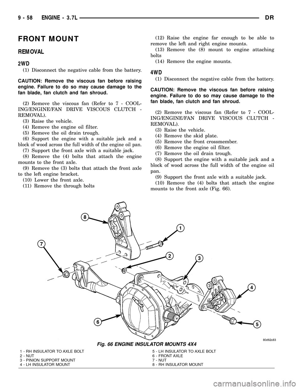
(8) Remove the (4) bolts that attach the engine
mounts to the front axle.
(9) Remove the (3) bolts that attach the front axle
to the left engine bracket.
(10) Lower the front axle.
(11) Remove the through bolts(12) Raise the engine far enough to be able to
remove the left and right engine mounts.
(13) Remove the (8) mount to engine attaching
bolts
(14) Remove the engine mounts.
4WD
(1) Disconnect the negative cable from the battery.
CAUTION: Remove the viscous fan before raising
engine. Failure to do so may cause damage to the
fan blade, fan clutch and fan shroud.
(2) Remove the viscous fan (Refer to 7 - COOL-
ING/ENGINE/FAN DRIVE VISCOUS CLUTCH -
REMOVAL).
(3) Raise the vehicle.
(4) Remove the skid plate.
(5) Remove the front crossmember.
(6) Remove the engine oil filter.
(7) Remove the oil drain trough.
(8) Support the engine with a suitable jack and a
block of wood across the full width of the engine oil
pan.
(9) Support the front axle with a suitable jack.
(10) Remove the (4) bolts that attach the engine
mounts to the front axle (Fig. 66).
Fig. 66 ENGINE INSULATOR MOUNTS 4X4
1 - RH INSULATOR TO AXLE BOLT
2 - NUT
3 - PINION SUPPORT MOUNT
4 - LH INSULATOR MOUNT5 - LH INSULATOR TO AXLE BOLT
6 - FRONT AXLE
7 - NUT
8 - RH INSULATOR MOUNT
9 - 58 ENGINE - 3.7LDR
Page 1282 of 2627
(11) Remove the (3) bolts that attach the front axle
to the left engine bracket.
(12) Lower the front axle.
(13) Remove the (6) through bolts
(14) Raise the engine far enough to be able to
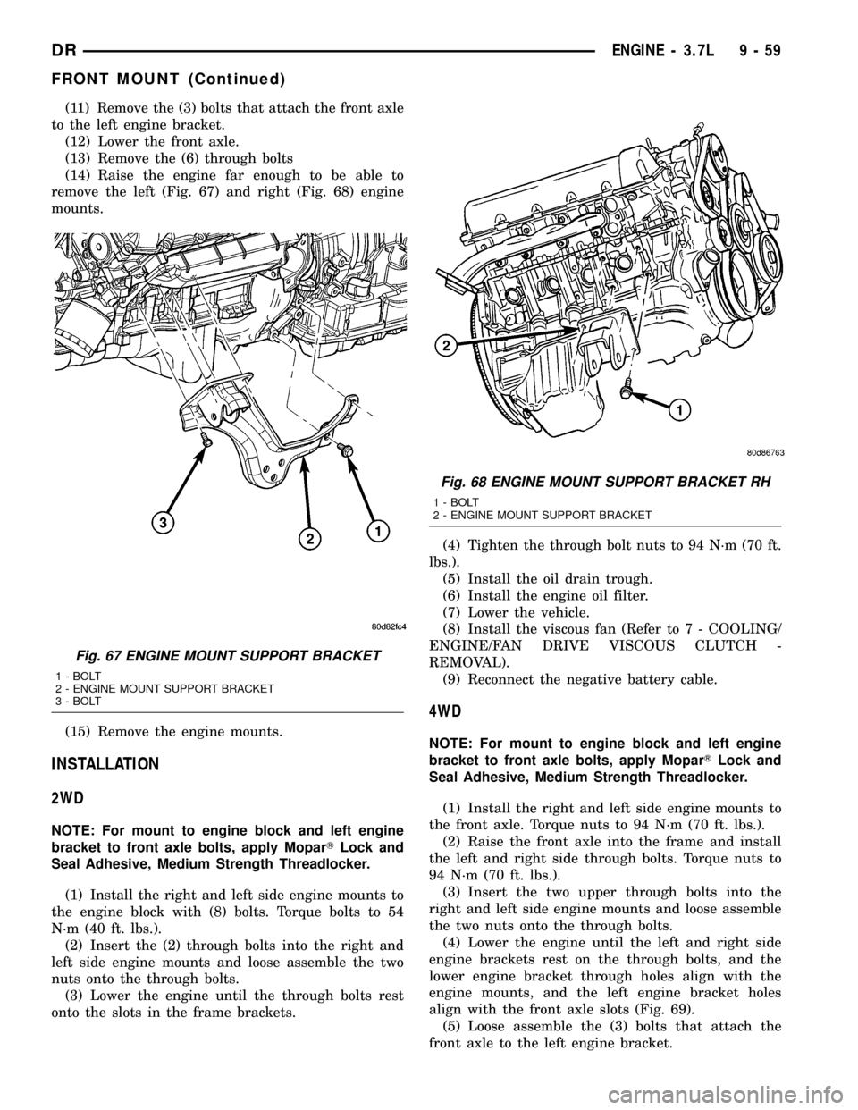
remove the left (Fig. 67) and right (Fig. 68) engine
mounts.
(15) Remove the engine mounts.
INSTALLATION
2WD
NOTE: For mount to engine block and left engine
bracket to front axle bolts, apply MoparTLock and
Seal Adhesive, Medium Strength Threadlocker.
(1) Install the right and left side engine mounts to
the engine block with (8) bolts. Torque bolts to 54
N´m (40 ft. lbs.).
(2) Insert the (2) through bolts into the right and
left side engine mounts and loose assemble the two
nuts onto the through bolts.
(3) Lower the engine until the through bolts rest
onto the slots in the frame brackets.(4) Tighten the through bolt nuts to 94 N´m (70 ft.
lbs.).
(5) Install the oil drain trough.
(6) Install the engine oil filter.
(7) Lower the vehicle.
(8) Install the viscous fan (Refer to 7 - COOLING/
ENGINE/FAN DRIVE VISCOUS CLUTCH -
REMOVAL).
(9) Reconnect the negative battery cable.
4WD
NOTE: For mount to engine block and left engine
bracket to front axle bolts, apply MoparTLock and
Seal Adhesive, Medium Strength Threadlocker.
(1) Install the right and left side engine mounts to
the front axle. Torque nuts to 94 N´m (70 ft. lbs.).
(2) Raise the front axle into the frame and install
the left and right side through bolts. Torque nuts to
94 N´m (70 ft. lbs.).
(3) Insert the two upper through bolts into the
right and left side engine mounts and loose assemble
the two nuts onto the through bolts.
(4) Lower the engine until the left and right side
engine brackets rest on the through bolts, and the
lower engine bracket through holes align with the
engine mounts, and the left engine bracket holes
align with the front axle slots (Fig. 69).
(5) Loose assemble the (3) bolts that attach the
front axle to the left engine bracket.
Fig. 67 ENGINE MOUNT SUPPORT BRACKET
1 - BOLT
2 - ENGINE MOUNT SUPPORT BRACKET
3 - BOLT
Fig. 68 ENGINE MOUNT SUPPORT BRACKET RH
1 - BOLT
2 - ENGINE MOUNT SUPPORT BRACKET
DRENGINE - 3.7L 9 - 59
FRONT MOUNT (Continued)
Page 1284 of 2627
REAR MOUNT
REMOVAL
(1) Raise the vehicle on a hoist.
(2) Using a suitable jack, support transmission.
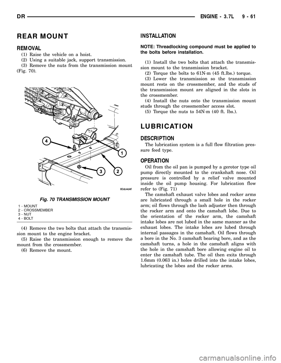
(3) Remove the nuts from the transmission mount
(Fig. 70).
(4) Remove the two bolts that attach the transmis-
sion mount to the engine bracket.
(5) Raise the transmission enough to remove the
mount from the crossmember.
(6) Remove the mount.
INSTALLATION
NOTE: Threadlocking compound must be applied to
the bolts before installation.
(1) Install the two bolts that attach the transmis-
sion mount to the transmission bracket.
(2) Torque the bolts to 61N´m (45 ft.lbs.) torque.
(3) Lower the transmission so the transmission
mount rests on the crossmember, and the studs of
the transmission mount are aligned in the slots in
the crossmember.
(4) Install the nuts onto the transmission mount
studs through the crossmember access slot.
(5) Torque the nuts to 54N´m (40 ft. lbs.).
LUBRICATION
DESCRIPTION
The lubrication system is a full flow filtration pres-
sure feed type.
OPERATION
Oil from the oil pan is pumped by a gerotor type oil
pump directly mounted to the crankshaft nose. Oil
pressure is controlled by a relief valve mounted
inside the oil pump housing. For lubrication flow
refer to (Fig. 71)
The camshaft exhaust valve lobes and rocker arms
are lubricated through a small hole in the rocker
arm; oil flows through the lash adjuster then through
the rocker arm and onto the camshaft lobe. Due to
the orientation of the rocker arm, the camshaft
intake lobes are not lubed in the same manner as the
exhaust lobes. The intake lobes are lubed through
internal passages in the camshaft. Oil flows through
a bore in the No. 3 camshaft bearing bore, and as the
camshaft turns, a hole in the camshaft aligns with
the hole in the camshaft bore allowing engine oil to
enter the camshaft tube. The oil then exits through
1.6mm (0.063 in.) holes drilled into the intake lobes,
lubricating the lobes and the rocker arms.
Fig. 70 TRANSMISSION MOUNT
1 - MOUNT
2 - CROSSMEMBER
3 - NUT
4 - BOLT
DRENGINE - 3.7L 9 - 61