1998 DODGE RAM 1500 light
[x] Cancel search: lightPage 2299 of 2627
Adhesion Promoter/Surface Modifier:
Adhesion Promoters/Surface Modifiers are required
for certain plastics. All three categories may have
plastics that require the use of adhesion promoter/
surface modifiers. Always follow repair material man-
ufacturer's plastic identification and repair
procedures.
SAFETY PRECAUTION AND WARNINGS
WARNING:
²EYE PROTECTION SHOULD BE USED WHEN
SERVICING COMPONENTS. PERSONAL INJURY
CAN RESULT.
²USE AN OSHA APPROVED BREATHING MASK
WHEN MIXING EPOXY, GRINDING, AND SPRAYING
PAINT OR SOLVENTS IN A CONFINED AREA. PER-
SONAL INJURY CAN RESULT.²AVOID PROLONGED SKIN CONTACT WITH
RESIN, PETROLEUM, OR ALCOHOL BASED SOL-
VENTS. PERSONAL INJURY CAN RESULT.
²DO NOT VENTURE UNDER A HOISTED VEHI-
CLE THAT IS NOT PROPERLY SUPPORTED ON
SAFETY STANDS. PERSONAL INJURY CAN
RESULT.
NOTE:
²When holes must be drilled or cut in body pan-
els, verify locations of internal body components
and electrical wiring. Damage to vehicle can result.
²Do not use abrasive chemicals or compounds
on undamaged painted surfaces around repair
areas. Damage to finish can result.
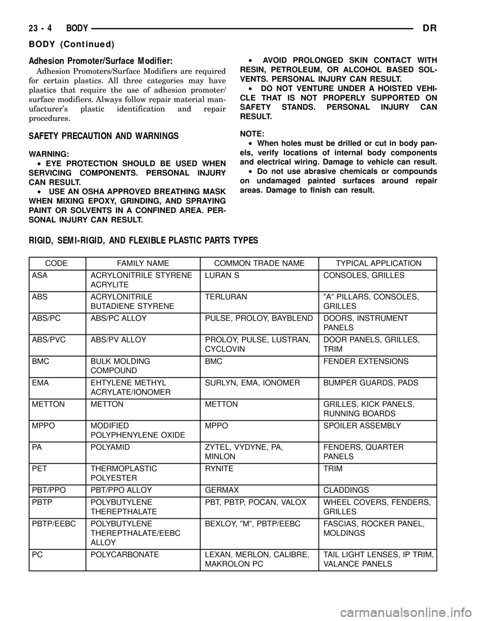
RIGID, SEMI-RIGID, AND FLEXIBLE PLASTIC PARTS TYPES
CODE FAMILY NAME COMMON TRADE NAME TYPICAL APPLICATION
ASA ACRYLONITRILE STYRENE
ACRYLITELURAN S CONSOLES, GRILLES
ABS ACRYLONITRILE
BUTADIENE STYRENETERLURAN9A9PILLARS, CONSOLES,
GRILLES
ABS/PC ABS/PC ALLOY PULSE, PROLOY, BAYBLEND DOORS, INSTRUMENT
PANELS
ABS/PVC ABS/PV ALLOY PROLOY, PULSE, LUSTRAN,
CYCLOVINDOOR PANELS, GRILLES,
TRIM
BMC BULK MOLDING
COMPOUNDBMC FENDER EXTENSIONS
EMA EHTYLENE METHYL
ACRYLATE/IONOMERSURLYN, EMA, IONOMER BUMPER GUARDS, PADS
METTON METTON METTON GRILLES, KICK PANELS,
RUNNING BOARDS
MPPO MODIFIED
POLYPHENYLENE OXIDEMPPO SPOILER ASSEMBLY
PA POLYAMID ZYTEL, VYDYNE, PA,
MINLONFENDERS, QUARTER
PANELS
PET THERMOPLASTIC
POLYESTERRYNITE TRIM
PBT/PPO PBT/PPO ALLOY GERMAX CLADDINGS
PBTP POLYBUTYLENE
THEREPTHALATEPBT, PBTP, POCAN, VALOX WHEEL COVERS, FENDERS,
GRILLES
PBTP/EEBC POLYBUTYLENE
THEREPTHALATE/EEBC
ALLOYBEXLOY,9M9, PBTP/EEBC FASCIAS, ROCKER PANEL,
MOLDINGS
PC POLYCARBONATE LEXAN, MERLON, CALIBRE,
MAKROLON PCTAIL LIGHT LENSES, IP TRIM,
VALANCE PANELS
23 - 4 BODYDR
BODY (Continued)
Page 2301 of 2627
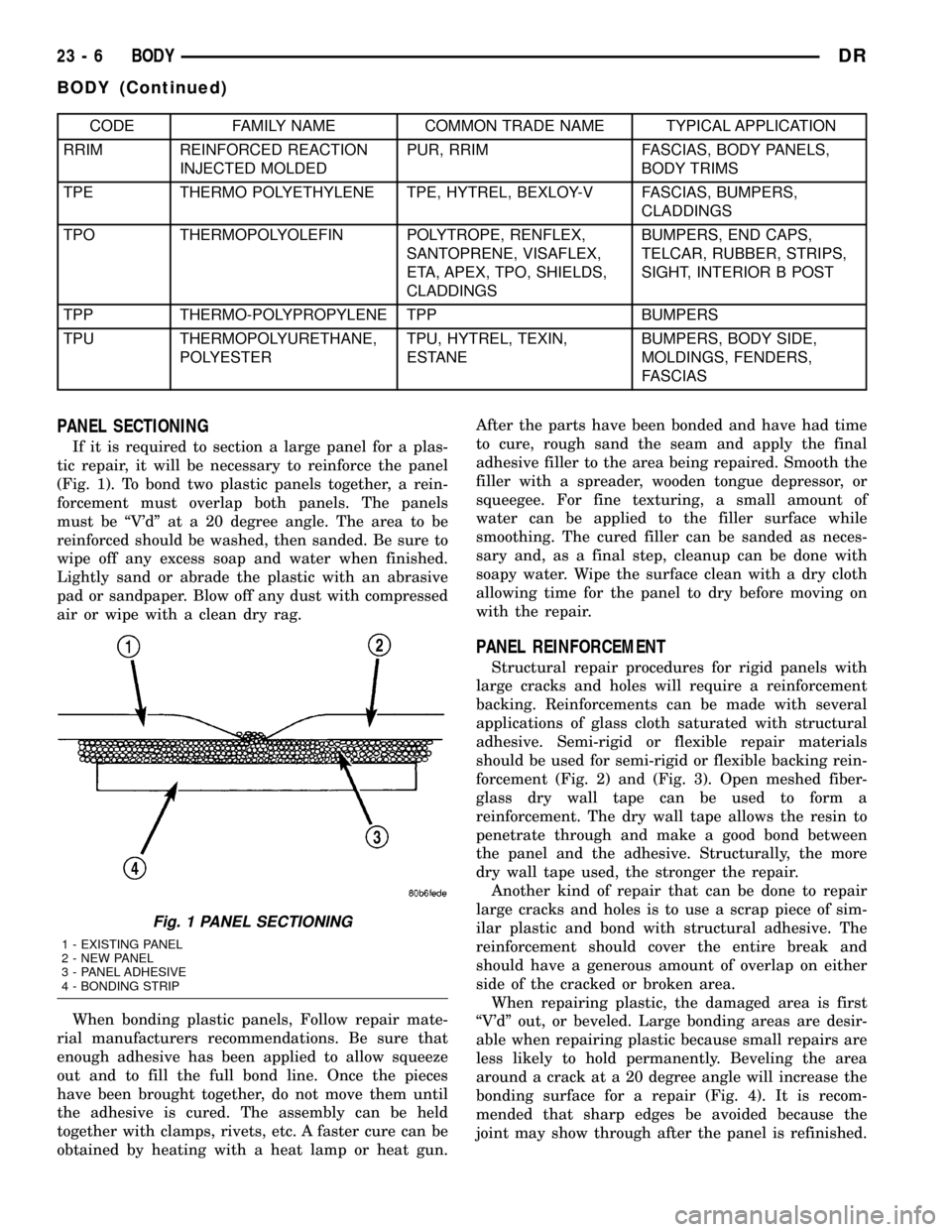
CODE FAMILY NAME COMMON TRADE NAME TYPICAL APPLICATION
RRIM REINFORCED REACTION
INJECTED MOLDEDPUR, RRIM FASCIAS, BODY PANELS,
BODY TRIMS
TPE THERMO POLYETHYLENE TPE, HYTREL, BEXLOY-V FASCIAS, BUMPERS,
CLADDINGS
TPO THERMOPOLYOLEFIN POLYTROPE, RENFLEX,
SANTOPRENE, VISAFLEX,
ETA, APEX, TPO, SHIELDS,
CLADDINGSBUMPERS, END CAPS,
TELCAR, RUBBER, STRIPS,
SIGHT, INTERIOR B POST
TPP THERMO-POLYPROPYLENE TPP BUMPERS
TPU THERMOPOLYURETHANE,
POLYESTERTPU, HYTREL, TEXIN,
ESTANEBUMPERS, BODY SIDE,
MOLDINGS, FENDERS,
FASCIAS
PANEL SECTIONING
If it is required to section a large panel for a plas-
tic repair, it will be necessary to reinforce the panel
(Fig. 1). To bond two plastic panels together, a rein-
forcement must overlap both panels. The panels
must be ªV'dº at a 20 degree angle. The area to be
reinforced should be washed, then sanded. Be sure to
wipe off any excess soap and water when finished.
Lightly sand or abrade the plastic with an abrasive
pad or sandpaper. Blow off any dust with compressed
air or wipe with a clean dry rag.
When bonding plastic panels, Follow repair mate-
rial manufacturers recommendations. Be sure that
enough adhesive has been applied to allow squeeze
out and to fill the full bond line. Once the pieces
have been brought together, do not move them until
the adhesive is cured. The assembly can be held
together with clamps, rivets, etc. A faster cure can be
obtained by heating with a heat lamp or heat gun.After the parts have been bonded and have had time
to cure, rough sand the seam and apply the final
adhesive filler to the area being repaired. Smooth the
filler with a spreader, wooden tongue depressor, or
squeegee. For fine texturing, a small amount of
water can be applied to the filler surface while
smoothing. The cured filler can be sanded as neces-
sary and, as a final step, cleanup can be done with
soapy water. Wipe the surface clean with a dry cloth
allowing time for the panel to dry before moving on
with the repair.
PANEL REINFORCEMENT
Structural repair procedures for rigid panels with
large cracks and holes will require a reinforcement
backing. Reinforcements can be made with several
applications of glass cloth saturated with structural
adhesive. Semi-rigid or flexible repair materials
should be used for semi-rigid or flexible backing rein-
forcement (Fig. 2) and (Fig. 3). Open meshed fiber-
glass dry wall tape can be used to form a
reinforcement. The dry wall tape allows the resin to
penetrate through and make a good bond between
the panel and the adhesive. Structurally, the more
dry wall tape used, the stronger the repair.
Another kind of repair that can be done to repair
large cracks and holes is to use a scrap piece of sim-
ilar plastic and bond with structural adhesive. The
reinforcement should cover the entire break and
should have a generous amount of overlap on either
side of the cracked or broken area.
When repairing plastic, the damaged area is first
ªV'dº out, or beveled. Large bonding areas are desir-
able when repairing plastic because small repairs are
less likely to hold permanently. Beveling the area
around a crack at a 20 degree angle will increase the
bonding surface for a repair (Fig. 4). It is recom-
mended that sharp edges be avoided because the
joint may show through after the panel is refinished.
Fig. 1 PANEL SECTIONING
1 - EXISTING PANEL
2 - NEW PANEL
3 - PANEL ADHESIVE
4 - BONDING STRIP
23 - 6 BODYDR
BODY (Continued)
Page 2319 of 2627

ADJUSTMENTS
ADJUSTMENT
(1) Using a grease pencil or equivalent, mark the
position of the striker to aid in adjustment.
(2) Loosen the striker bolts.
(3) Change the striker position to adjust the rear
gap and flush measurement. (Refer to 23 - BODY/
BODY STRUCTURE/GAP AND FLUSH - SPECIFI-
CATIONS)
(4) Tighten the bolts to 28 N´m (21 ft. lbs.).
LOCK CYLINDER
REMOVAL
(1) Remove the exterior handle. (Refer to 23 -
BODY/DOOR - FRONT/EXTERIOR HANDLE -
REMOVAL)
(2) Remove the clip and remove the lock cylinder
lever and switch, if equipped.
(3) Remove the screw and remove the lock cylin-
der. (Fig. 11)
INSTALLATION
(1) Install the lock cylinder and install the screw.
(2) Install the lock cylinder switch, if equipped,
lever and retaining clip.
(3) Install the exterior handle. (Refer to 23 -
BODY/DOOR - FRONT/EXTERIOR HANDLE -
INSTALLATION)
TRIM PANEL
REMOVAL
(1) Remove the window crank, if equipped. (Fig.
13)
(2) Remove the interior handle. (Refer to 23 -
BODY/DOOR - FRONT/INSIDE HANDLE ACTUA-
TOR - REMOVAL)
(3) Remove the screws at the mirror flag and near
the inside handle. (Fig. 12)
CAUTION: Trim panel is attached to the door using
hooks molded into the panel. Do not pull the trim
panel straight off or damage to the panel and/or
power switch assembly may occur.
(4) Lift the trim panel up off the belt seal and
attachment hooks and separate the panel from the
door slightly.
(5) Disconnect the power window switch electrical
connector, if equipped, and remove the trim panel.
INSTALLATION
(1) Install the window switch into the trim panel,
if equipped.
(2) Position the trim panel onto the lower hooks
and connect the power window switch electrical con-
nector, if equipped.
(3) Position the remaining trim panel attachment
hooks into the door panel and seat the trim panel
into the belt seal fully.
(4) Install the screws near the inside handle and
at the mirror flag.
Fig. 11 LOCK CYLINDER
1 - LOCK CYLINDER
2 - EXTERIOR HANDLE
3 - SCREW
4 - LOCK SWITCH WIRE HARNESS
Fig. 12 TRIM PANEL ASSEMBLY
1 - SCREW INSERT (2)
2 - SCREWS (2)
3 - DOOR TRIM PANEL
4 - LOWER SCREWS (3)
5 - ATTACHMENT HOOKS
23 - 24 DOOR - FRONTDR
LATCH STRIKER (Continued)
Page 2328 of 2627
ADJUSTMENTS
ADJUSTMENT
(1) Locate access hole and remove the mylar tape
covering it. (Fig. 8)
(2) Insert a 5/32-inch hex-wrench through hole and
into adjustment screw. Loosen screw.
(3) Operate outside handle several times to release
any restriction because of mis-alignment.
(4) Tighten adjustment screw to 3 N´m (30 in.
lbs.).
(5) Test handle for proper operation.
LATCH STRIKER
REMOVAL
(1) Using a grease pencil or equivalent, mark the
position of the striker.
(2) Remove the bolts and remove the striker.
INSTALLATION
(1) Install the striker and install the bolts.
(2) Tighten the bolts to 28 N´m (21 ft. lbs.).
(3) Adjust the striker if needed. (Refer to 23 -
BODY/DOOR - FRONT/LATCH STRIKER - ADJUST-
MENTS)
ADJUSTMENTS
ADJUSTMENT
(1) Using a grease pencil or equivalent, mark the
position of the striker to aid in adjustment.
(2) Loosen the striker bolts.
(3) Change the striker position to adjust the rear
gap and flush measurement. (Refer to 23 - BODY/BODY STRUCTURE/GAP AND FLUSH - SPECIFI-
CATIONS)
(4) Tighten the bolts to 28 N´m (21 ft. lbs.).
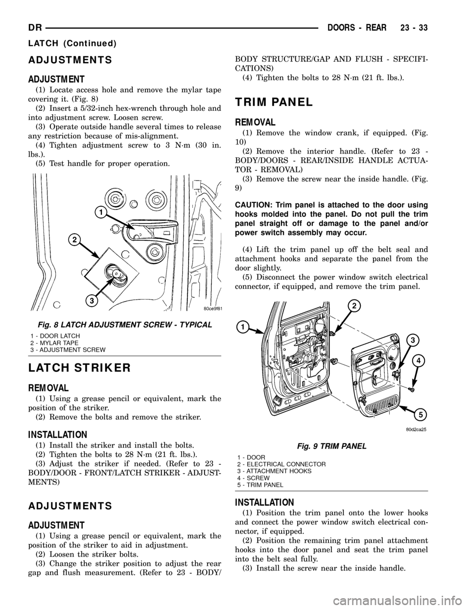
TRIM PANEL
REMOVAL
(1) Remove the window crank, if equipped. (Fig.
10)
(2) Remove the interior handle. (Refer to 23 -
BODY/DOORS - REAR/INSIDE HANDLE ACTUA-
TOR - REMOVAL)
(3) Remove the screw near the inside handle. (Fig.
9)
CAUTION: Trim panel is attached to the door using
hooks molded into the panel. Do not pull the trim
panel straight off or damage to the panel and/or
power switch assembly may occur.
(4) Lift the trim panel up off the belt seal and
attachment hooks and separate the panel from the
door slightly.
(5) Disconnect the power window switch electrical
connector, if equipped, and remove the trim panel.
INSTALLATION
(1) Position the trim panel onto the lower hooks
and connect the power window switch electrical con-
nector, if equipped.
(2) Position the remaining trim panel attachment
hooks into the door panel and seat the trim panel
into the belt seal fully.
(3) Install the screw near the inside handle.
Fig. 8 LATCH ADJUSTMENT SCREW - TYPICAL
1 - DOOR LATCH
2 - MYLAR TAPE
3 - ADJUSTMENT SCREW
Fig. 9 TRIM PANEL
1 - DOOR
2 - ELECTRICAL CONNECTOR
3 - ATTACHMENT HOOKS
4 - SCREW
5 - TRIM PANEL
DRDOORS - REAR 23 - 33
LATCH (Continued)
Page 2334 of 2627

FRONT FENDER
REMOVAL
(1) Remove the antenna, if equipped. (Refer to 8 -
ELECTRICAL/AUDIO/ANTENNA BODY & CABLE -
REMOVAL)
(2) Remove the battery tray, if required. (Refer to 8
- ELECTRICAL/BATTERY SYSTEM/TRAY -
REMOVAL)
(3) Remove the cowl grille. (Refer to 23 - BODY/
EXTERIOR/COWL GRILLE - REMOVAL)
(4) Remove the headlamp unit. (Refer to 8 - ELEC-
TRICAL/LAMPS/LIGHTING - EXTERIOR/HEAD-
LAMP UNIT - REMOVAL)
(5) Remove the wheelhouse splash shield. (Refer to
23 - BODY/EXTERIOR/FRONT WHEELHOUSE
SPLASH SHIELD - REMOVAL)
(6) Remove the inside and lower bolts. (Fig. 6)
(7) Remove the two bolts below the headlamp.
(8) Remove the hinge support bolt at the cowl.
(9) Remove the three bolts along the fender rail.
INSTALLATION
(1) Install the three bolts along the upper fender
rail and tighten to 9 N´m (80 in. lbs.).
(2) Install the upper hinge support bolt at the cowl
and tighten to 17 N´m (13 ft. lbs.).
(3) Install the two bolts below the headlamp and
tighten to 9 N´m (80 in. lbs.).(4) Install the inside and lower bolts and tighten
to 17 N´m (13 ft. lbs.).
(5) Check the fender positioning and adjust as
required by adding shims. (Refer to 23 - BODY/
BODY STRUCTURE/GAP AND FLUSH - SPECIFI-
CATIONS)
(6) Install the wheelhouse splash shield. (Refer to
23 - BODY/EXTERIOR/FRONT WHEELHOUSE
SPLASH SHIELD - INSTALLATION)
(7) Install the headlamp unit. (Refer to 8 - ELEC-
TRICAL/LAMPS/LIGHTING - EXTERIOR/HEAD-
LAMP UNIT - INSTALLATION)
(8) Install the cowl grille. (Refer to 23 - BODY/EX-
TERIOR/COWL GRILLE - INSTALLATION)
(9) Install the battery tray, if required. (Refer to 8
- ELECTRICAL/BATTERY SYSTEM/TRAY -
INSTALLATION)
(10) Install the antenna, if required. (Refer to 8 -
ELECTRICAL/AUDIO/ANTENNA BODY & CABLE -
INSTALLATION)
FUEL FILL DOOR
REMOVAL
(1) Open fill door and remove the bolts. (Fig. 7)
(2) Remove the door.
INSTALLATION
(1) Install the fuel fill door.
(2) Install the bolts and tighten to 9 N´m (80 in.
lbs.).
Fig. 6 FRONT FENDER
1 - HOOD HINGE SUPPORT BOLT (1)
2 - HOOD HINGE
3 - INNER BOLT (1)
4 - FRONT BOLTS (2)
5 - LOWER BOLT INSERT
6 - FENDER
7 - UPPER BOLTS (3)
Fig. 7 FUEL FILL DOOR
1 - FUEL FILL DOOR
2 - BOLTS (2)
DREXTERIOR 23 - 39
Page 2339 of 2627
(2) Connect the heated mirror electrical connec-
tors, if equipped.
NOTE: Pressure must be applied equally over the
center portion of the mirror to engage the mirror
glass retaining clip fully.
(3) Position the glass over the motor mounting and
seat fully. Make sure the retaining clip seats fully.
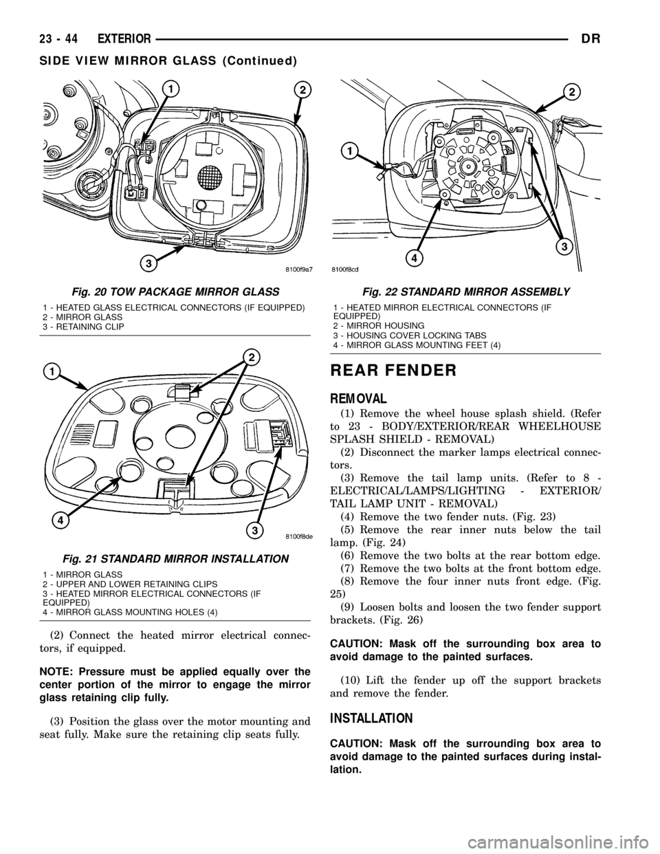
REAR FENDER
REMOVAL
(1) Remove the wheel house splash shield. (Refer
to 23 - BODY/EXTERIOR/REAR WHEELHOUSE
SPLASH SHIELD - REMOVAL)
(2) Disconnect the marker lamps electrical connec-
tors.
(3) Remove the tail lamp units. (Refer to 8 -
ELECTRICAL/LAMPS/LIGHTING - EXTERIOR/
TAIL LAMP UNIT - REMOVAL)
(4) Remove the two fender nuts. (Fig. 23)
(5) Remove the rear inner nuts below the tail
lamp. (Fig. 24)
(6) Remove the two bolts at the rear bottom edge.
(7) Remove the two bolts at the front bottom edge.
(8) Remove the four inner nuts front edge. (Fig.
25)
(9) Loosen bolts and loosen the two fender support
brackets. (Fig. 26)
CAUTION: Mask off the surrounding box area to
avoid damage to the painted surfaces.
(10) Lift the fender up off the support brackets
and remove the fender.
INSTALLATION
CAUTION: Mask off the surrounding box area to
avoid damage to the painted surfaces during instal-
lation.
Fig. 20 TOW PACKAGE MIRROR GLASS
1 - HEATED GLASS ELECTRICAL CONNECTORS (IF EQUIPPED)
2 - MIRROR GLASS
3 - RETAINING CLIP
Fig. 21 STANDARD MIRROR INSTALLATION
1 - MIRROR GLASS
2 - UPPER AND LOWER RETAINING CLIPS
3 - HEATED MIRROR ELECTRICAL CONNECTORS (IF
EQUIPPED)
4 - MIRROR GLASS MOUNTING HOLES (4)
Fig. 22 STANDARD MIRROR ASSEMBLY
1 - HEATED MIRROR ELECTRICAL CONNECTORS (IF
EQUIPPED)
2 - MIRROR HOUSING
3 - HOUSING COVER LOCKING TABS
4 - MIRROR GLASS MOUNTING FEET (4)
23 - 44 EXTERIORDR
SIDE VIEW MIRROR GLASS (Continued)
Page 2340 of 2627
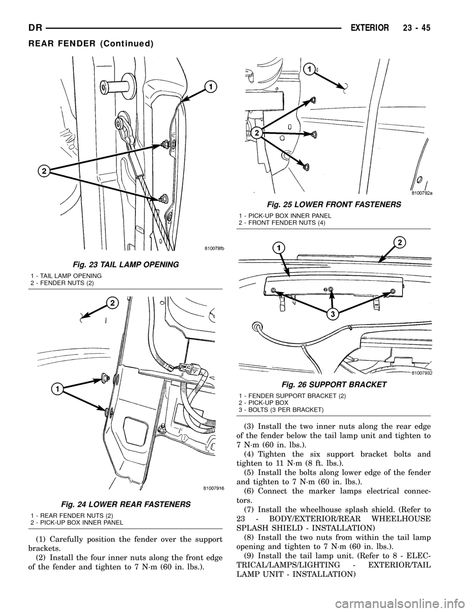
(1) Carefully position the fender over the support
brackets.
(2) Install the four inner nuts along the front edge
of the fender and tighten to 7 N´m (60 in. lbs.).(3) Install the two inner nuts along the rear edge
of the fender below the tail lamp unit and tighten to
7 N´m (60 in. lbs.).
(4) Tighten the six support bracket bolts and
tighten to 11 N´m (8 ft. lbs.).
(5) Install the bolts along lower edge of the fender
and tighten to 7 N´m (60 in. lbs.).
(6) Connect the marker lamps electrical connec-
tors.
(7) Install the wheelhouse splash shield. (Refer to
23 - BODY/EXTERIOR/REAR WHEELHOUSE
SPLASH SHIELD - INSTALLATION)
(8) Install the two nuts from within the tail lamp
opening and tighten to 7 N´m (60 in. lbs.).
(9) Install the tail lamp unit. (Refer to 8 - ELEC-
TRICAL/LAMPS/LIGHTING - EXTERIOR/TAIL
LAMP UNIT - INSTALLATION)
Fig. 23 TAIL LAMP OPENING
1 - TAIL LAMP OPENING
2 - FENDER NUTS (2)
Fig. 24 LOWER REAR FASTENERS
1 - REAR FENDER NUTS (2)
2 - PICK-UP BOX INNER PANEL
Fig. 25 LOWER FRONT FASTENERS
1 - PICK-UP BOX INNER PANEL
2 - FRONT FENDER NUTS (4)
Fig. 26 SUPPORT BRACKET
1 - FENDER SUPPORT BRACKET (2)
2 - PICK-UP BOX
3 - BOLTS (3 PER BRACKET)
DREXTERIOR 23 - 45
REAR FENDER (Continued)
Page 2351 of 2627

(8) Install the left a-pillar trim. (Refer to 23 -
BODY/INTERIOR/A-PILLAR TRIM - INSTALLA-
TION)
(9) Position the left end cap and seat the attach-
ment clips fully.
(10) Install the right side mounting bolts on the
a-pillar and one right mounting bolt on the cowl side
panel and tighten to 12 N´m (9 ft. lbs.).
(11) Install the right a-pillar trim panel. (Refer to
23 - BODY/INTERIOR/A-PILLAR TRIM - INSTAL-
LATION)
(12) Position the right end cap and seat the
attachment clips fully.
(13) Install the one HVAC mounting screw.
(14) Connect the radio antenna.
(15) Connect the two electrical connectors at the
right cowl panel.
(16) Install the right cowl trim cover. (Refer to 23 -
BODY/INTERIOR/COWL TRIM - INSTALLATION)
(17) Connect the air bag control module electrical
connector.
(18) Install the center bracket bolts and tighten to
12 N´m (9 ft. lbs.).
(19) Install the floor console, if equipped. (Refer to
23 - BODY/INTERIOR/FLOOR CONSOLE - INSTAL-
LATION)
(20) Install the air bag control module cover, if
equipped.
(21) Connect the park brake release handle actua-
tor rod.
(22) Install the hood release handle and tighten
the screws.
(23) Install the two bolts at the column support
bracket and tighten to 14 N´m (10 ft. lbs.).
(24) Install the steering column. (Refer to 19 -
STEERING/COLUMN - INSTALLATION)
(25) Connect the wire harness electrical connectors
above the brake pedal.
(26) Install the two top instrument panel bolts and
tighten to 12 N´m (9 ft. lbs.).
(27) Install the four top instrument panel screws.
(28) Install the instrument panel top cover. (Refer
to 23 - BODY/INSTRUMENT PANEL/INSTRUMENT
PANEL TOP COVER - INSTALLATION)
INSTRUMENT PANEL
HEADLAMP SWITCH BEZEL
REMOVAL
WARNING: ON VEHICLES EQUIPPED WITH AIR-
BAGS, DISABLE THE AIRBAG SYSTEM BEFORE
ATTEMPTING ANY STEERING WHEEL, STEERING
COLUMN, SEAT BELT TENSIONER, OR INSTRU-
MENT PANEL COMPONENT DIAGNOSIS OR SER-VICE. DISCONNECT AND ISOLATE THE BATTERY
NEGATIVE (GROUND) CABLE, THEN WAIT TWO
MINUTES FOR THE AIRBAG SYSTEM CAPACITOR
TO DISCHARGE BEFORE PERFORMING FURTHER
DIAGNOSIS OR SERVICE. THIS IS THE ONLY SURE
WAY TO DISABLE THE AIRBAG SYSTEM. FAILURE
TO TAKE THE PROPER PRECAUTIONS COULD
RESULT IN ACCIDENTAL AIRBAG DEPLOYMENT
AND POSSIBLE PERSONAL INJURY.
(1) Using a trim stick C-4755 or equivalent,
release the top clips on the steering column opening
cover and the lower drivers side bezel.
(2) Using a trim stick C-4755 or equivalent,
release the switch bezel. (Fig. 17)
(3) Disconnect the electrical connector and remove
the bezel.
INSTALLATION
WARNING: ON VEHICLES EQUIPPED WITH AIR-
BAGS, DISABLE THE AIRBAG SYSTEM BEFORE
ATTEMPTING ANY STEERING WHEEL, STEERING
COLUMN, SEAT BELT TENSIONER, OR INSTRU-
MENT PANEL COMPONENT DIAGNOSIS OR SER-
VICE. DISCONNECT AND ISOLATE THE BATTERY
NEGATIVE (GROUND) CABLE, THEN WAIT TWO
MINUTES FOR THE AIRBAG SYSTEM CAPACITOR
TO DISCHARGE BEFORE PERFORMING FURTHER
DIAGNOSIS OR SERVICE. THIS IS THE ONLY SURE
WAY TO DISABLE THE AIRBAG SYSTEM. FAILURE
TO TAKE THE PROPER PRECAUTIONS COULD
RESULT IN ACCIDENTAL AIRBAG DEPLOYMENT
AND POSSIBLE PERSONAL INJURY.
(1) Connect the electrical connector.
Fig. 17 HEADLIGHT SWITCH BEZEL
1 - SWITCH BEZEL
2 - INSTRUMENT PANEL
3 - ELECTRICAL CONNECTOR
4 - HEADLIGHT SWITCH
23 - 56 INSTRUMENT PANELDR
INSTRUMENT PANEL ASSEMBLY (Continued)