1998 DODGE RAM 1500 Fuel delivery
[x] Cancel search: Fuel deliveryPage 1468 of 2627
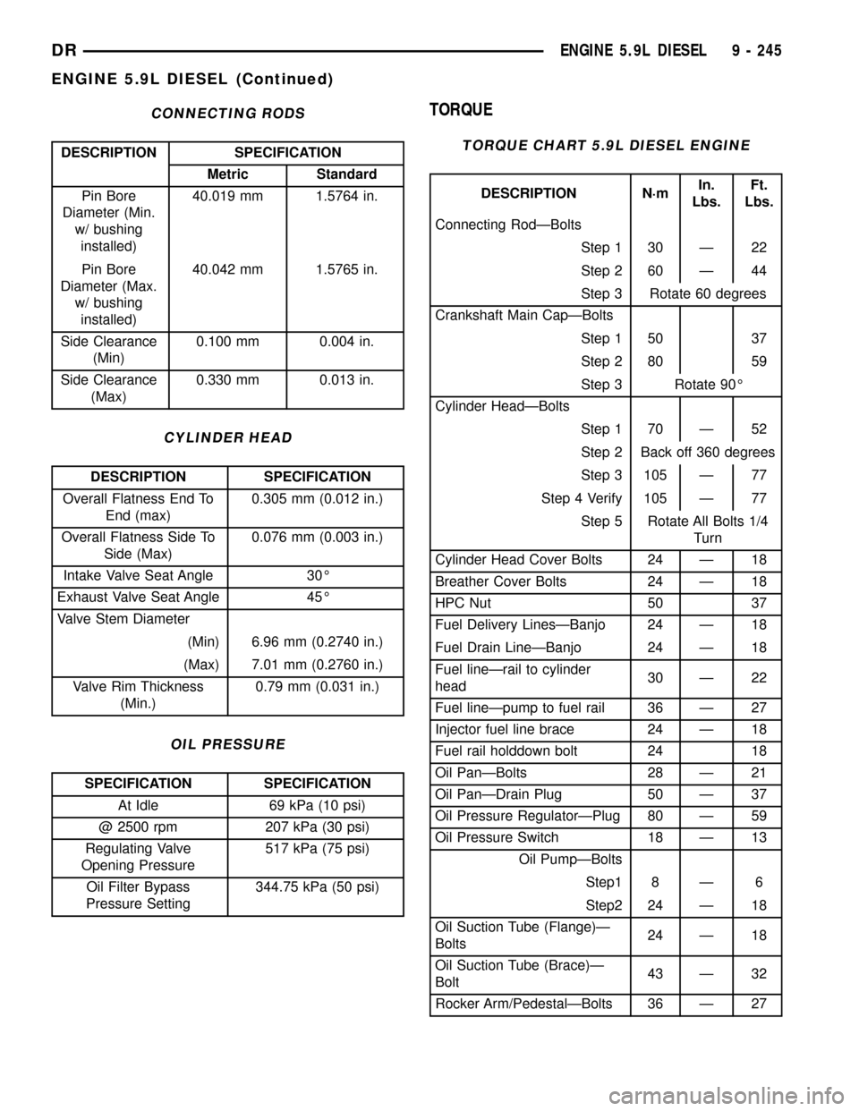
CONNECTING RODS
DESCRIPTION SPECIFICATION
Metric Standard
Pin Bore
Diameter (Min.
w/ bushing
installed)40.019 mm 1.5764 in.
Pin Bore
Diameter (Max.
w/ bushing
installed)40.042 mm 1.5765 in.
Side Clearance
(Min)0.100 mm 0.004 in.
Side Clearance
(Max)0.330 mm 0.013 in.
CYLINDER HEAD
DESCRIPTION SPECIFICATION
Overall Flatness End To
End (max)0.305 mm (0.012 in.)
Overall Flatness Side To
Side (Max)0.076 mm (0.003 in.)
Intake Valve Seat Angle 30É
Exhaust Valve Seat Angle 45É
Valve Stem Diameter
(Min) 6.96 mm (0.2740 in.)
(Max) 7.01 mm (0.2760 in.)
Valve Rim Thickness
(Min.)0.79 mm (0.031 in.)
OIL PRESSURE
SPECIFICATION SPECIFICATION
At Idle 69 kPa (10 psi)
@ 2500 rpm 207 kPa (30 psi)
Regulating Valve
Opening Pressure517 kPa (75 psi)
Oil Filter Bypass
Pressure Setting344.75 kPa (50 psi)
TORQUE
TORQUE CHART 5.9L DIESEL ENGINE
DESCRIPTION N´mIn.
Lbs.Ft.
Lbs.
Connecting RodÐBolts
Step 1 30 Ð 22
Step 2 60 Ð 44
Step 3 Rotate 60 degrees
Crankshaft Main CapÐBolts
Step 1 50 37
Step 2 80 59
Step 3 Rotate 90É
Cylinder HeadÐBolts
Step 1 70 Ð 52
Step 2 Back off 360 degrees
Step 3 105 Ð 77
Step 4 Verify 105 Ð 77
Step 5 Rotate All Bolts 1/4
Turn
Cylinder Head Cover Bolts 24 Ð 18
Breather Cover Bolts 24 Ð 18
HPC Nut 50 37
Fuel Delivery LinesÐBanjo 24 Ð 18
Fuel Drain LineÐBanjo 24 Ð 18
Fuel lineÐrail to cylinder
head30 Ð 22
Fuel lineÐpump to fuel rail 36 Ð 27
Injector fuel line brace 24 Ð 18
Fuel rail holddown bolt 24 18
Oil PanÐBolts 28 Ð 21
Oil PanÐDrain Plug 50 Ð 37
Oil Pressure RegulatorÐPlug 80 Ð 59
Oil Pressure Switch 18 Ð 13
Oil PumpÐBolts
Step1 8 Ð 6
Step2 24 Ð 18
Oil Suction Tube (Flange)Ð
Bolts24 Ð 18
Oil Suction Tube (Brace)Ð
Bolt43 Ð 32
Rocker Arm/PedestalÐBolts 36 Ð 27
DRENGINE 5.9L DIESEL 9 - 245
ENGINE 5.9L DIESEL (Continued)
Page 1520 of 2627
(13) Install the cooling fan (Refer to 7 - COOLING/
ENGINE/RADIATOR FAN - INSTALLATION).
(14) Connect battery negative cables.
(15) Start engine and check for oil leaks.
INTAKE MANIFOLD
REMOVAL
(1) Disconnect the battery negative cables.
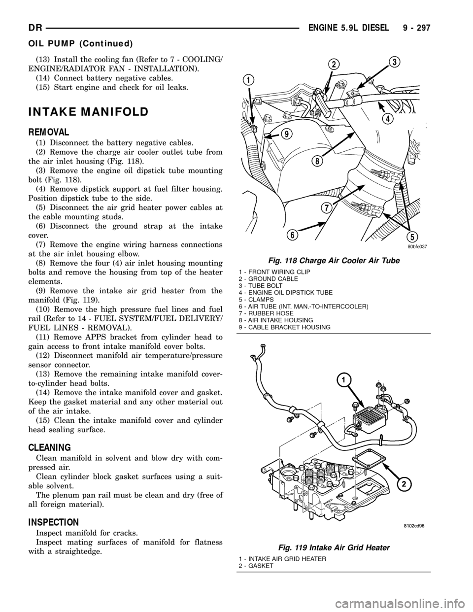
(2) Remove the charge air cooler outlet tube from
the air inlet housing (Fig. 118).
(3) Remove the engine oil dipstick tube mounting
bolt (Fig. 118).
(4) Remove dipstick support at fuel filter housing.
Position dipstick tube to the side.
(5) Disconnect the air grid heater power cables at
the cable mounting studs.
(6) Disconnect the ground strap at the intake
cover.
(7) Remove the engine wiring harness connections
at the air inlet housing elbow.
(8) Remove the four (4) air inlet housing mounting
bolts and remove the housing from top of the heater
elements.
(9) Remove the intake air grid heater from the
manifold (Fig. 119).
(10) Remove the high pressure fuel lines and fuel
rail (Refer to 14 - FUEL SYSTEM/FUEL DELIVERY/
FUEL LINES - REMOVAL).
(11) Remove APPS bracket from cylinder head to
gain access to front intake manifold cover bolts.
(12) Disconnect manifold air temperature/pressure
sensor connector.
(13) Remove the remaining intake manifold cover-
to-cylinder head bolts.
(14) Remove the intake manifold cover and gasket.
Keep the gasket material and any other material out
of the air intake.
(15) Clean the intake manifold cover and cylinder
head sealing surface.
CLEANING
Clean manifold in solvent and blow dry with com-
pressed air.
Clean cylinder block gasket surfaces using a suit-
able solvent.
The plenum pan rail must be clean and dry (free of
all foreign material).
INSPECTION
Inspect manifold for cracks.
Inspect mating surfaces of manifold for flatness
with a straightedge.
Fig. 118 Charge Air Cooler Air Tube
1 - FRONT WIRING CLIP
2 - GROUND CABLE
3 - TUBE BOLT
4 - ENGINE OIL DIPSTICK TUBE
5 - CLAMPS
6 - AIR TUBE (INT. MAN.-TO-INTERCOOLER)
7 - RUBBER HOSE
8 - AIR INTAKE HOUSING
9 - CABLE BRACKET HOUSING
Fig. 119 Intake Air Grid Heater
1 - INTAKE AIR GRID HEATER
2 - GASKET
DRENGINE 5.9L DIESEL 9 - 297
OIL PUMP (Continued)
Page 1521 of 2627
INSTALLATION
(1) Using a new gasket, install the intake manifold
cover.
(2) Install the cover-to-cylinder head bolts that do
not hold down the fuel rail. Tighten the bolts to 24
N´m (18 ft. lbs.) torque.
(3) Install the high pressure rail and fuel lines
(Refer to 14 - FUEL SYSTEM/FUEL DELIVERY/
FUEL LINES - INSTALLATION).
(4) Using two (2) new gaskets, install the intake
air grid heater and air inlet housing. Position the
ground cable and install and tighten the bolts to 24
N´m (18 ft. lbs.) torque.
(5) Connect the manifold air temperature/pressure
sensor connector.
(6) Install and tighten the air intake heater power
supply nuts to 14 N´m (120 in. lbs.) torque.
(7) Install the APPS bracket. Torque fasteners to
43 N´m (32ft lbs.) torque.
(8) Install oil dipstick tube support at fuel filter
housing.
(9) Install the engine oil dipstick tube and mount-
ing bolt.
(10) Position the charge air cooler outlet tube onto
the air inlet housing. Tighten the clamps to 11 N´m
(100 in. lbs.) torque.
(11) Attach the engine wire harness to the air inlet
housing at two locations.
(12) Prime the fuel system. Refer to the fuel prim-
ing procedure in Group 14, Fuel System.
(13) Connect the battery negative cables.
EXHAUST MANIFOLD
REMOVAL
(1) Disconnect the battery negative cables.
(2) Raise vehicle on hoist.
(3) Disconnect the exhaust pipe from the turbo-
charger elbow.
(4) Disconnect oil drain tube from turbocharger.
(5) Lower vehicle.
(6) Disconnect the turbocharger air inlet hose.
(7) Remove air cleaner assembly.
(8) Disconnect the turbocharger oil supply line.
(9) Disconnect the charge air cooler inlet pipe from
the turbocharger.
(10) Remove the turbocharger and gasket from the
exhaust manifold.
(11) Remove the cab heater return pipe nuts from
the exhaust manifold stud. Position the tube out of
the way.
(12) Remove heat shield.
(13) Remove exhaust manifold bolt lockplates.
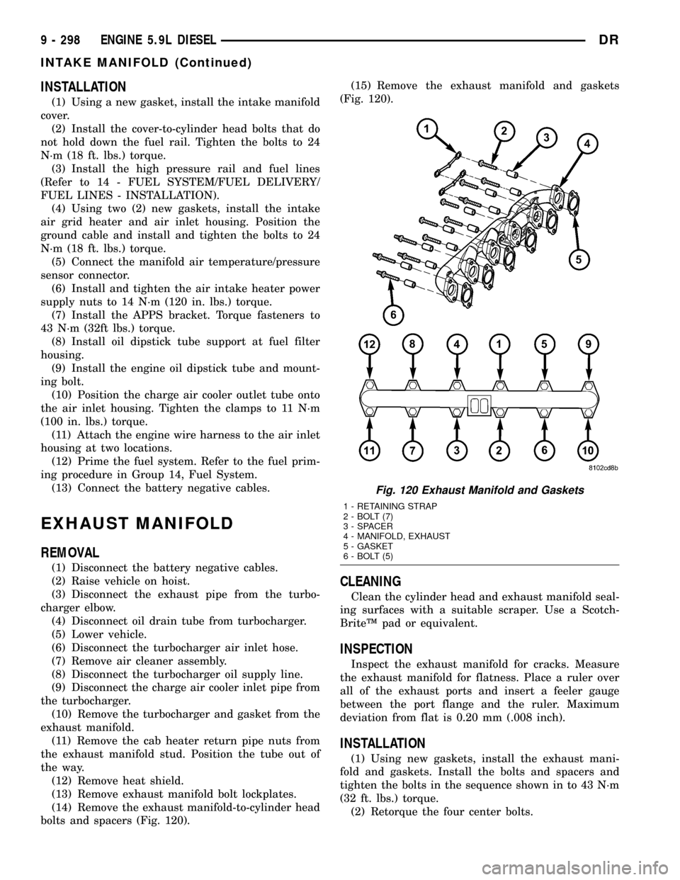
(14) Remove the exhaust manifold-to-cylinder head
bolts and spacers (Fig. 120).(15) Remove the exhaust manifold and gaskets
(Fig. 120).
CLEANING
Clean the cylinder head and exhaust manifold seal-
ing surfaces with a suitable scraper. Use a Scotch-
BriteŸ pad or equivalent.
INSPECTION
Inspect the exhaust manifold for cracks. Measure
the exhaust manifold for flatness. Place a ruler over
all of the exhaust ports and insert a feeler gauge
between the port flange and the ruler. Maximum
deviation from flat is 0.20 mm (.008 inch).
INSTALLATION
(1) Using new gaskets, install the exhaust mani-
fold and gaskets. Install the bolts and spacers and
tighten the bolts in the sequence shown in to 43 N´m
(32 ft. lbs.) torque.
(2) Retorque the four center bolts.
Fig. 120 Exhaust Manifold and Gaskets
1 - RETAINING STRAP
2 - BOLT (7)
3 - SPACER
4 - MANIFOLD, EXHAUST
5 - GASKET
6 - BOLT (5)
9 - 298 ENGINE 5.9L DIESELDR
INTAKE MANIFOLD (Continued)
Page 1522 of 2627
(3) Install heat shield and torque nuts to 15 Nm
(11 ft. lbs.).
(4) Install cab heater tube.
(5) Install exhaust manifold bolt retention straps.
(6) Install the cab heater return hose to the man-
ifold bolt stud. Tighten the nut to 24 N´m (18 ft. lbs.)
torque.
(7) Install the turbocharger and a new gasket.
Apply anti-seize to the studs and then tighten the
turbocharger mounting nuts to 43 N´m (32 ft. lbs.)
torque.
(8)Pre-lube the turbocharger.Pour 50 to 60 cc
(2 to 3 oz.) clean engine oil in the oil supply line fit-
ting on the turbo. Rotate the turbocharger impeller
by hand to distrubute the oil thoroughly.
(9) Install and tighten the oil supply line fitting
nut to 24 N´m (18 ft. lbs.) torque.
(10) Position the charge air cooler inlet pipe to the
turbocharger. With the clamp in position, tighten the
clamp nut to 11 N´m (100 in. lbs.) torque.
(11) Position the air inlet hose to the turbocharger.
Tighten the clamp to 11 N´m (100 in. lbs.) torque.
(12) Raise vehicle on hoist.
(13) Install the oil drain tube and a new gasket to
the turbocharger. Tighten the drain tube bolts to 24
N´m (18 ft. lbs.) torque.
(14) Connect the exhaust pipe to the turbocharger
and tighten the bolts to 11 N´m (100 ft. lbs.) torque.
(15) Lower the vehicle.
(16) Connect the battery negative cables.
(17) Start the engine to check for leaks.
VALVE TIMING
STANDARD PROCEDURE - TIMING
VERIFICATION
(1) Remove the cylinder head cover(Refer to 9 -
ENGINE/CYLINDER HEAD/CYLINDER HEAD
COVER(S) - REMOVAL).
(2) Remove fuel injector from cylinder number
1(Refer to 14 - FUEL SYSTEM/FUEL INJECTION/
FUEL INJECTOR - REMOVAL).
(3) Using Special Tool 7471B rotate the engine
until the TDC mark on the damper is at 12 o'clock.
(4) Using a 8 in.x 1/4 in. dowel rod inserted into
cylinder number 1, rock the crankshaft back and
forth to verify piston number 1 is at TDC.
(5) With cylinder number still at TDC, inspect the
keyway on the crankshaft gear for proper alignment
(12 o'clock position).
(6) If the keyway is not at 12 o'clock position
replace the crankshaft gear assembly.
(7) If the keyway is at 12 o'clock position, remove
front gear cover and verify timing mark alignmentbetween the camshaft gear and crankshaft gear, if
not aligned inspect keyway on camshaft gear.
(8) Inspect keyway on camshaft gear for proper
alignment with the key in the camshaft, if alignment
is off replace the camshaft/gear assembly.
(9) If timing marks alignment is off and no dam-
age is found at either the crankshaft or camshaft
gear keyways, realign timing marks as necessary.
GEAR HOUSING
REMOVAL
(1) Disconnect the battery negative cables.
(2) Raise vehicle on hoist.
(3) Partially drain engine coolant into container
suitable for re-use (Refer to 7 - COOLING - STAN-
DARD PROCEDURE).
(4) Lower vehicle.
(5) Remove radiator upper hose.
(6) Disconnect coolant recovery bottle hose from
radiator filler neck and lift bottle off of fan shroud.
(7) Disconnect windshield washer pump supply
hose and electrical connections and lift washer bottle
off of fan shroud.
(8) Remove lower fan shroud fasteners. Disconnect
fan drive wire harness.
(9) Remove the upper fan shroud-to-radiator
mounting bolts.
(10) Remove viscous fan/drive assembly (Refer to 7
- COOLING/ENGINE/RADIATOR FAN - REMOVAL).
(11) Remove the accessory drive belt (Refer to 7 -
COOLING/ACCESSORY DRIVE/DRIVE BELTS -
REMOVAL).
(12) Remove the cooling fan support/hub from the
front of the engine.
(13) Raise the vehicle on hoist.
(14) Remove the crankshaft damper (Refer to 9 -
ENGINE/ENGINE BLOCK/VIBRATION DAMPER -
REMOVAL) and speed indicator ring.
(15) Lower the vehicle.
(16) Remove the power steering pump.
(17) Remove the accessory drive belt tensioner.
(18) Remove the gear cover-to-housing bolts and
gently pry the cover away from the housing, taking
care not to mar the gasket surfaces.
(19) Remove the fuel injection pump (Refer to 14 -
FUEL SYSTEM/FUEL DELIVERY/FUEL INJEC-
TION PUMP - REMOVAL).
(20) Disconnect the camshaft position sensor con-
nector.
(21) Disconnect and remove engine speed sensor.
(22) Remove the camshaft (Refer to 9 - ENGINE/
ENGINE BLOCK/CAMSHAFT & BEARINGS (IN
BLOCK) - REMOVAL).
(23) Remove the six front oil pan fasteners.
DRENGINE 5.9L DIESEL 9 - 299
EXHAUST MANIFOLD (Continued)
Page 1523 of 2627
(24) Remove the gear housing fasteners.
NOTE: Use care when removing the gear housing,
to avoid damage to the oil pan gasket, as the gas-
ket will be reused if it is not damaged.
(25) Slide a feeler gauge between the gear housing
and oil pan gasket, to break the gasket seal.
(26) Remove the gear housing and gasket.
(27) Clean the gasket material from the cylinder
block and gear housing.
INSTALLATION
(1) Inspect oil pan gasket. If torn, gasket must be
replaced.
(2) Install a new gear housing gasket onto cylinder
block and trim any excesss gasket material flush to
oil pan rail.
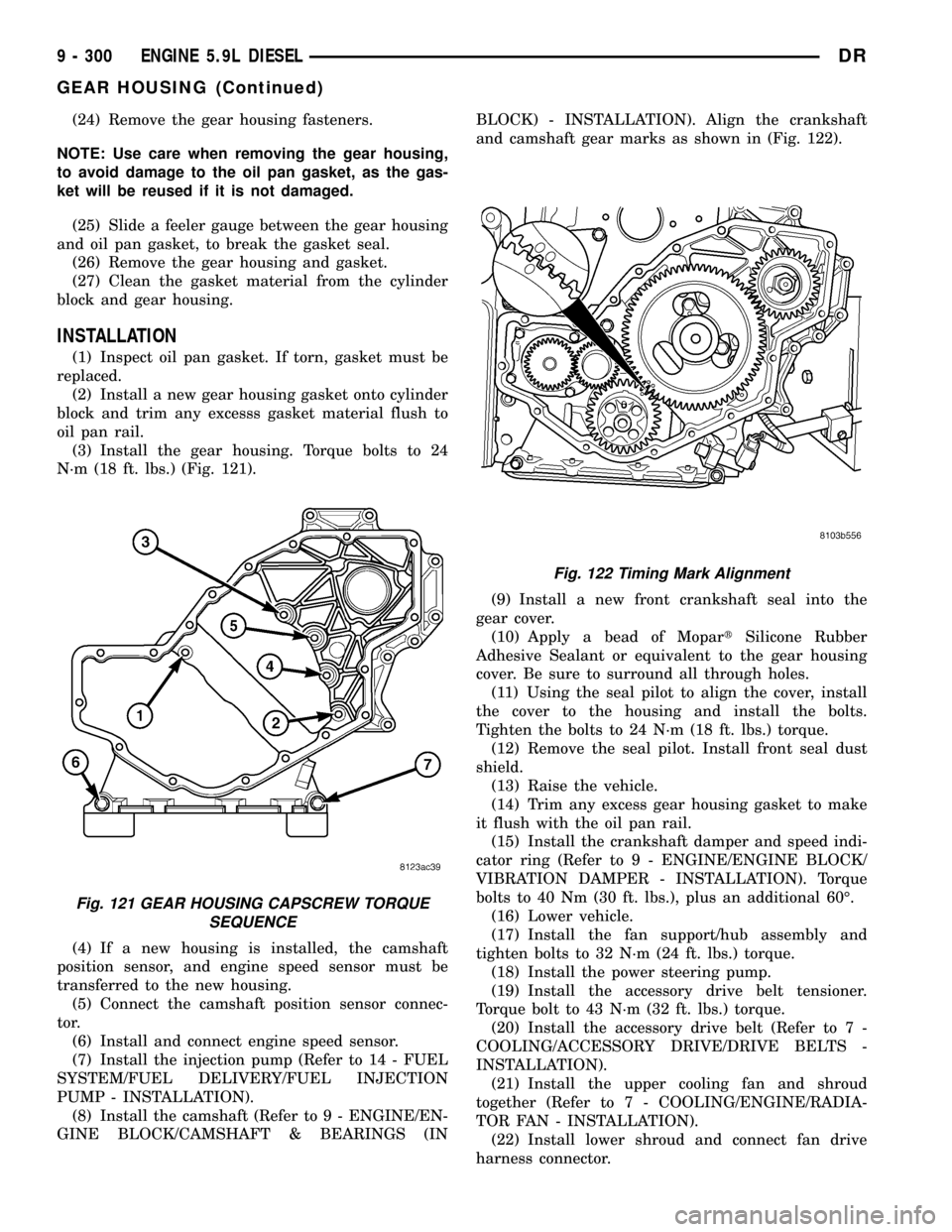
(3) Install the gear housing. Torque bolts to 24
N´m (18 ft. lbs.) (Fig. 121).
(4) If a new housing is installed, the camshaft
position sensor, and engine speed sensor must be
transferred to the new housing.
(5) Connect the camshaft position sensor connec-
tor.
(6) Install and connect engine speed sensor.
(7) Install the injection pump (Refer to 14 - FUEL
SYSTEM/FUEL DELIVERY/FUEL INJECTION
PUMP - INSTALLATION).
(8) Install the camshaft (Refer to 9 - ENGINE/EN-
GINE BLOCK/CAMSHAFT & BEARINGS (INBLOCK) - INSTALLATION). Align the crankshaft
and camshaft gear marks as shown in (Fig. 122).
(9) Install a new front crankshaft seal into the
gear cover.
(10) Apply a bead of MopartSilicone Rubber
Adhesive Sealant or equivalent to the gear housing
cover. Be sure to surround all through holes.
(11) Using the seal pilot to align the cover, install
the cover to the housing and install the bolts.
Tighten the bolts to 24 N´m (18 ft. lbs.) torque.
(12) Remove the seal pilot. Install front seal dust
shield.
(13) Raise the vehicle.
(14) Trim any excess gear housing gasket to make
it flush with the oil pan rail.
(15) Install the crankshaft damper and speed indi-
cator ring (Refer to 9 - ENGINE/ENGINE BLOCK/
VIBRATION DAMPER - INSTALLATION). Torque
bolts to 40 Nm (30 ft. lbs.), plus an additional 60É.
(16) Lower vehicle.
(17) Install the fan support/hub assembly and
tighten bolts to 32 N´m (24 ft. lbs.) torque.
(18) Install the power steering pump.
(19) Install the accessory drive belt tensioner.
Torque bolt to 43 N´m (32 ft. lbs.) torque.
(20) Install the accessory drive belt (Refer to 7 -
COOLING/ACCESSORY DRIVE/DRIVE BELTS -
INSTALLATION).
(21) Install the upper cooling fan and shroud
together (Refer to 7 - COOLING/ENGINE/RADIA-
TOR FAN - INSTALLATION).
(22) Install lower shroud and connect fan drive
harness connector.
Fig. 121 GEAR HOUSING CAPSCREW TORQUE
SEQUENCE
Fig. 122 Timing Mark Alignment
9 - 300 ENGINE 5.9L DIESELDR
GEAR HOUSING (Continued)
Page 1570 of 2627
FUEL SYSTEM
TABLE OF CONTENTS
page page
FUEL DELIVERY - GAS....................1
FUEL INJECTION - GAS...................21FUEL DELIVERY - DIESEL.................44
FUEL INJECTION - DIESEL................68
FUEL DELIVERY - GAS
TABLE OF CONTENTS
page page
FUEL DELIVERY - GAS
DESCRIPTION..........................1
OPERATION............................2
STANDARD PROCEDURE - FUEL SYSTEM
PRESSURE RELEASE...................2
SPECIFICATIONS
FUEL SYSTEM PRESSURE..............3
TORQUE - FUEL SYSTEM - EXCEPT
DIESEL..............................3
SPECIAL TOOLS
FUEL SYSTEM........................5
FUEL FILTER/PRESSURE REGULATOR
DESCRIPTION..........................5
OPERATION............................6
FUEL LEVEL SENDING UNIT / SENSOR
DESCRIPTION..........................6
OPERATION............................6
REMOVAL.............................7
INSTALLATION..........................7
FUEL LINES
DESCRIPTION..........................7
QUICK CONNECT FITTING
DESCRIPTION..........................8STANDARD PROCEDURE - QUICK-CONNECT
FITTINGS............................8
FUEL PUMP
DESCRIPTION.........................11
OPERATION...........................11
FUEL PUMP MODULE
DESCRIPTION.........................11
OPERATION...........................11
REMOVAL.............................12
INSTALLATION.........................12
FUEL RAIL
DESCRIPTION.........................12
OPERATION...........................12
REMOVAL.............................13
INSTALLATION.........................15
FUEL TANK
DESCRIPTION.........................17
OPERATION...........................17
REMOVAL- EXCEPT DIESEL..............17
INSTALLATION - EXCEPT DIESEL..........19
INLET FILTER
REMOVAL.............................20
INSTALLATION.........................20
FUEL DELIVERY - GAS
DESCRIPTION
The fuel delivery system consists of:
²a fuel pump module containing the electric fuel
pump, fuel filter/fuel pressure regulator, fuel gauge
sending unit (fuel level sensor) and a secondary fuel
filter located at the bottom of the pump module
²fuel tubes/lines/hoses
²a combination fuel filter/fuel pressure regulator
²quick-connect fittings²fuel injector rail
²fuel tank
²fuel tank filler/vent tube assembly
²fuel tank filler tube cap
²accelerator pedal
²throttle cable
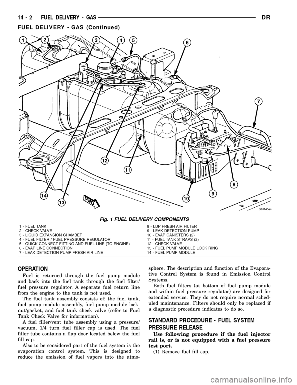
Certain fuel delivery components can be found in
(Fig. 1).
DRFUEL SYSTEM 14 - 1
Page 1571 of 2627
OPERATION
Fuel is returned through the fuel pump module
and back into the fuel tank through the fuel filter/
fuel pressure regulator. A separate fuel return line
from the engine to the tank is not used.
The fuel tank assembly consists of: the fuel tank,
fuel pump module assembly, fuel pump module lock-
nut/gasket, and fuel tank check valve (refer to Fuel
Tank Check Valve for information).
A fuel filler/vent tube assembly using a pressure/
vacuum, 1/4 turn fuel filler cap is used. The fuel
filler tube contains a flap door located below the fuel
fill cap.
Also to be considered part of the fuel system is the
evaporation control system. This is designed to
reduce the emission of fuel vapors into the atmo-sphere. The description and function of the Evapora-
tive Control System is found in Emission Control
Systems.
Both fuel filters (at bottom of fuel pump module
and within fuel pressure regulator) are designed for
extended service. They do not require normal sched-
uled maintenance. Filters should only be replaced if
a diagnostic procedure indicates to do so.
STANDARD PROCEDURE - FUEL SYSTEM
PRESSURE RELEASE
Use following procedure if the fuel injector
rail is, or is not equipped with a fuel pressure
test port.
(1) Remove fuel fill cap.
Fig. 1 FUEL DELIVERY COMPONENTS
1 - FUEL TANK 8 - LDP FRESH AIR FILTER
2 - CHECK VALVE 9 - LEAK DETECTION PUMP
3 - LIQUID EXPANSION CHAMBER 10 - EVAP CANISTERS (2)
4 - FUEL FILTER / FUEL PRESSURE REGULATOR 11 - FUEL TANK STRAPS (2)
5 - QUICK-CONNECT FITTING AND FUEL LINE (TO ENGINE) 12 - CHECK VALVE
6 - EVAP LINE CONNECTION 13 - FUEL PUMP MODULE LOCK RING
7 - LEAK DETECTION PUMP FRESH AIR LINE 14 - FUEL PUMP MODULE
14 - 2 FUEL DELIVERY - GASDR
FUEL DELIVERY - GAS (Continued)
Page 1572 of 2627
(2) Remove fuel pump relay from Power Distribu-
tion Center (PDC). For location of relay, refer to label
on underside of PDC cover.
(3) Start and run engine until it stalls.
(4) Attempt restarting engine until it will no
longer run.
(5) Turn ignition key to OFF position.
CAUTION: Steps 1, 2, 3 and 4 must be performed to
relieve high pressure fuel from within fuel rail. Do
not attempt to use following steps to relieve this
pressure as excessive fuel will be forced into a cyl-
inder chamber.
(6) Unplug connector from any fuel injector.
(7) Attach one end of a jumper wire with alligator
clips (18 gauge or smaller) to either injector terminal.
(8) Connect other end of jumper wire to positive
side of battery.(9) Connect one end of a second jumper wire to
remaining injector terminal.
CAUTION: Powering an injector for more than a few
seconds will permanently damage the injector.
(10) Momentarily touch other end of jumper wire
to negative terminal of battery for no more than a
few seconds.
(11) Place a rag or towel below fuel line quick-con-
nect fitting at fuel rail.
(12) Disconnect quick-connect fitting at fuel rail.
Refer to Quick-Connect Fittings.
(13) Return fuel pump relay to PDC.
(14) One or more Diagnostic Trouble Codes (DTC's)
may have been stored in PCM memory due to fuel
pump relay removal. The DRBtscan tool must be
used to erase a DTC.
SPECIFICATIONS
FUEL SYSTEM PRESSURE
58 psi +/- 2 psi
TORQUE - FUEL SYSTEM - EXCEPT DIESEL
DESCRIPTION N-m Ft. Lbs. In. Lbs.
Accelerator Pedal Bracket
Mounting12 - 105
Accelerator Pedal Position
Sensor Bracket-to-Battery
Tray Bolts3-30
Crankshaft Position
Sensor - 3.7L28 21 -
Crankshaft Position
Sensor - 4.7L28 21 -
Crankshaft Position
Sensor - 5.7L12 - 105 (+/-20)
Camshaft Position Sensor
- 3.7L12 - 106
Camshaft Position Sensor
- 4.7L12 - 106
Camshaft Position Sensor
- 5.7L12 9 105 (+/-) 20
Engine Coolant
Temperature Sensor -
3.7L11 - 9 6
Engine Coolant
Temperature Sensor -
4.7L11 - 9 6
DRFUEL DELIVERY - GAS 14 - 3
FUEL DELIVERY - GAS (Continued)