1998 DODGE RAM 1500 Brake servo
[x] Cancel search: Brake servoPage 832 of 2627

8W-30 FUEL/IGNITION SYSTEM
Component Page
A/C Compressor Clutch Relay............ 8W-30-9, 58
A/C Pressure Transducer......... 8W-30-23, 28, 29, 45
Accelerator Pedal Position Sensor . . . 8W-30-29, 47, 64, 65
Adjustable Pedal Motor................. 8W-30-61
Adjustable Pedal Relay.................. 8W-30-61
Adjustable Pedal Switch................. 8W-30-61
Ambient Temperature Sensor............. 8W-30-30
Auto Shut Down Relay................... 8W-30-4
Battery............................ 8W-30-52
Battery Temperature Sensor............ 8W-30-12, 56
Brake Lamp Switch............. 8W-30-8, 36, 57, 63
Camshaft Position Sensor........ 8W-30-10, 29, 45, 46
Capacitor........................... 8W-30-13
Clockspring..................... 8W-30-8, 36, 59
Coil On Plug No. 1.................. 8W-30-14, 39
Coil On Plug No. 2.................. 8W-30-15, 37
Coil On Plug No. 3.................. 8W-30-14, 39
Coil On Plug No. 4.................. 8W-30-15, 37
Coil On Plug No. 5.................. 8W-30-16, 39
Coil On Plug No. 6.................. 8W-30-13, 37
Coil On Plug No. 7.................. 8W-30-16, 39
Coil On Plug No. 8.................. 8W-30-13, 37
Condenser Fan Relay.................... 8W-30-9
Controller Antilock Brake............ 8W-30-6, 11, 57
Crankshaft Position Sensor............ 8W-30-10, 46
Data Link Connector............... 8W-30-9, 22, 55
Data Link Connector-Engine.............. 8W-30-51
EGR Solenoid................... 8W-30-28, 29, 32
Electronic Throttle Control Module.......... 8W-30-35
Engine Control Module....... 8W-30-42, 43, 44, 45, 46,
47, 48, 49, 50, 51, 52, 53, 54,
55, 56, 57, 58, 59, 60, 62, 63, 64, 65
Engine Coolant Temperature Sensor.... 8W-30-23, 41, 47
Engine Oil Pressure Switch.......... 8W-30-2, 53, 56
EVAP/Purge Solenoid................... 8W-30-12
Front Control Module................... 8W-30-61
Fuel Control Actuator................... 8W-30-50
Fuel Heater......................... 8W-30-60
Fuel Heater Relay..................... 8W-30-60
Fuel Injector No. 1.................. 8W-30-14, 40
Fuel Injector No. 2.................. 8W-30-15, 38
Fuel Injector No. 3.................. 8W-30-14, 40
Fuel Injector No. 4.................. 8W-30-15, 38
Fuel Injector No. 5.................. 8W-30-14, 40
Fuel Injector No. 6.................. 8W-30-15, 38
Fuel Injector No. 7.................. 8W-30-16, 40
Fuel Injector No. 8.................. 8W-30-13, 38
Fuel Injector Pack No. 1................. 8W-30-42
Fuel Injector Pack No. 2............ 8W-30-42, 43, 44
Fuel Injector Pack No. 3................. 8W-30-44
Fuel Pump Module................... 8W-30-3, 58
Fuel Pump Motor...................... 8W-30-48
Fuel Pump Relay....................... 8W-30-3
Fuse 2.............................. 8W-30-4
Fuse 5........................... 8W-30-25, 62
Fuse 12............................ 8W-30-60
Fuse 17............................. 8W-30-3
Fuse 19............................ 8W-30-52
Fuse 23............................. 8W-30-2Component Page
Fuse 36.......................... 8W-30-54, 61
Fuse 40............................ 8W-30-61
Fuse 49............................. 8W-30-4
Fuse 50..................... 8W-30-2, 55, 58, 62
Fusible Link......................... 8W-30-52
G104........................ 8W-30-3, 8, 25, 60
G105............................ 8W-30-56, 58
G107........... 8W-30-2, 7, 15, 18, 19, 20, 21, 30, 32
G114 .............................. 8W-30-53
G120............................ 8W-30-51, 60
G201............................... 8W-30-6
G202.............................. 8W-30-61
Generator......................... 8W-30-7, 51
Idle Air Control Motor................... 8W-30-9
Ignition Switch..................... 8W-30-6, 22
Inlet Air Temperature Sensor............. 8W-30-49
Input Speed Sensor.................... 8W-30-24
Instrument Cluster.................... 8W-30-30
Intake Air Heater Relay No. 1............. 8W-30-56
Intake Air Heater Relay No. 2............. 8W-30-56
Intake Air Temperature Sensor.......... 8W-30-23, 41
Intake Air Temperature/Manifold Absolute
Pressure Sensor..................... 8W-30-50
Integrated Power Module.... 8W-30-2, 3, 4, 9, 25, 52, 54,
55, 58, 60, 61, 62, 64
Knock Sensor........................ 8W-30-31
Knock Sensor-Left..................... 8W-30-33
Knock Sensor-Right.................... 8W-30-33
Lift Pump Motor...................... 8W-30-51
Line Pressure Sensor................... 8W-30-17
Manifold Absolute Pressure Sensor..... 8W-30-23, 29, 41
Natural Vacuum Leak Detection Assembly..... 8W-30-7
Output Speed Sensor................. 8W-30-24, 62
Oxygen Sensor 1/1 Upstream........... 8W-30-20, 21
Oxygen Sensor 1/2 Downstream......... 8W-30-18, 19
Oxygen Sensor 2/1 Upstream........... 8W-30-20, 21
Oxygen Sensor 2/2 Downstream......... 8W-30-18, 19
Oxygen Sensor Downstream Relay........... 8W-30-4
Power Steering Pressure Switch............ 8W-30-7
Powertrain Control Module....... 8W-30-2, 3, 4, 5, 6, 7,
8, 9, 10, 11, 12, 13, 14, 15, 16,
17, 18, 19, 20, 21, 22, 23, 24,
25, 26, 27, 28, 29, 30, 31, 32,
33, 35, 36, 37, 38, 39, 40, 41
PTCNo.1 ....................... 8W-30-3, 9, 58
Pto Switch........................... 8W-30-6
Speed Control Servo.................. 8W-30-8, 63
Speed Control Switch-Left............. 8W-30-36, 59
Speed Control Switch-Right............ 8W-30-36, 59
Starter Motor Relay.................. 8W-30-2, 64
Throttle Position Sensor................. 8W-30-17
Tow/Haul Overdrive Switch............. 8W-30-6, 64
Transmission Control Relay............ 8W-30-25, 62
Transmission Range Sensor............... 8W-30-64
Transmission Solenoid Assembly......... 8W-30-54, 62
Transmission Solenoid/TRS Assembly . 8W-30-5, 25, 26, 27
Vacuum Pump........................ 8W-30-58
Vistronic Fan Drive.................... 8W-30-54
Water In Fuel Sensor................ 8W-30-47, 48
DR8W-30 FUEL/IGNITION SYSTEM 8W - 30 - 1
Page 898 of 2627

8W-31 TRANSMISSION CONTROL SYSTEM
Component Page
Automatic Day/Night Mirror........... 8W-31-7
Brake Lamp Switch.................. 8W-31-9
Camshaft Position Sensor.............. 8W-31-6
Clockspring........................ 8W-31-10
Clutch Interlock Brake Switch......... 8W-31-11
Data Link Connector................ 8W-31-16
Engine Control Module......... 8W-31-7, 8, 9, 10
Front Control Module................. 8W-31-2
Fuse 5.......................... 8W-31-2, 8
Fuse 38.......................... 8W-31-2, 7
Fuse 43........................... 8W-31-11
Fuse 50............................ 8W-31-8
G104..................... 8W-31-2, 11, 14, 16
G107............................. 8W-31-14
G201........................... 8W-31-3, 10
Input Speed Sensor.................. 8W-31-5
Instrument Cluster................ 8W-31-7, 14
Integrated Power Module....... 8W-31-2, 7, 8, 11Component Page
Line Pressure Sensor................. 8W-31-6
Output Speed Sensor............... 8W-31-5, 8
Powertrain Control Module..... 8W-31-2, 3, 4, 5, 6
Speed Control Servo.................. 8W-31-9
Speed Control Switch-Left............ 8W-31-10
Speed Control Switch-Right........... 8W-31-10
Starter Motor Relay................. 8W-31-11
Tow/Haul Overdrive Switch......... 8W-31-3, 10
Transfer Case Control
Module.............. 8W-31-11, 12, 13, 14, 16
Transfer Case Mode Sensor........ 8W-31-12, 13
Transfer Case Selector Switch......... 8W-31-14
Transfer Case Shift Motor............ 8W-31-16
Transmission Control Relay.......... 8W-31-2, 8
Transmission Range Sensor............ 8W-31-7
Transmission Solenoid Assembly........ 8W-31-8
Transmission Solenoid/TRS Assembly . 8W-31-2, 3, 4
DR8W-31 TRANSMISSION CONTROL SYSTEM 8W - 31 - 1
Page 914 of 2627

8W-33 VEHICLE SPEED CONTROL
Component Page
Brake Lamp Switch.............. 8W-33-2, 4, 5
Center High Mounted Stop Lamp-
Aftermarket...................... 8W-33-2
Center High Mounted Stop Lamp/Cargo
Lamp........................... 8W-33-2
Clockspring..................... 8W-33-6, 7, 8
Controller Antilock Brake.............. 8W-33-3
Electric Brake Provision............... 8W-33-2
Engine Control Module............ 8W-33-3, 5, 8
Fuse 24............................ 8W-33-2Component Page
Fuse 30............................ 8W-33-4
G104............................ 8W-33-4, 5
G201.............................. 8W-33-2
Instrument Cluster................... 8W-33-2
Integrated Power Module............ 8W-33-2, 4
Powertrain Control Module........ 8W-33-3, 4, 8
PTCNo.1.......................... 8W-33-4
Speed Control Servo................ 8W-33-4, 5
Speed Control Switch-Left........... 8W-33-6, 7
Speed Control Switch-Right.......... 8W-33-6, 7
DR8W-33 VEHICLE SPEED CONTROL 8W - 33 - 1
Page 1146 of 2627

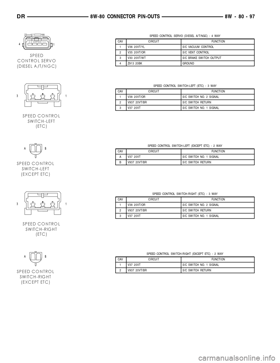
SPEED CONTROL SERVO (DIESEL A/T/NGC)-4WAY
CAV CIRCUIT FUNCTION
1 V36 20VT/YL S/C VACUUM CONTROL
2 V35 20VT/OR S/C VENT CONTROL
3 V30 20VT/WT S/C BRAKE SWITCH OUTPUT
4 Z913 20BK GROUND
SPEED CONTROL SWITCH-LEFT (ETC)-3WAY
CAV CIRCUIT FUNCTION
1 V38 20VT/OR S/C SWITCH NO. 2 SIGNAL
2 V937 20VT/BR S/C SWITCH RETURN
3 V37 20VT S/C SWITCH NO. 1 SIGNAL
SPEED CONTROL SWITCH-LEFT (EXCEPT ETC)-2WAY
CAV CIRCUIT FUNCTION
A V37 20VT S/C SWITCH NO. 1 SIGNAL
B V937 20VT/BR S/C SWITCH RETURN
SPEED CONTROL SWITCH-RIGHT (ETC)-3WAY
CAV CIRCUIT FUNCTION
1 V38 20VT/OR S/C SWITCH NO. 2 SIGNAL
2 V937 20VT/BR S/C SWITCH RETURN
3 V37 20VT S/C SWITCH NO. 1 SIGNAL
SPEED CONTROL SWITCH-RIGHT (EXCEPT ETC)-2WAY
CAV CIRCUIT FUNCTION
1 V37 20VT S/C SWITCH NO. 1 SIGNAL
2 V937 20VT/BR S/C SWITCH RETURN
DR8W-80 CONNECTOR PIN-OUTS 8W - 80 - 97
Page 1160 of 2627

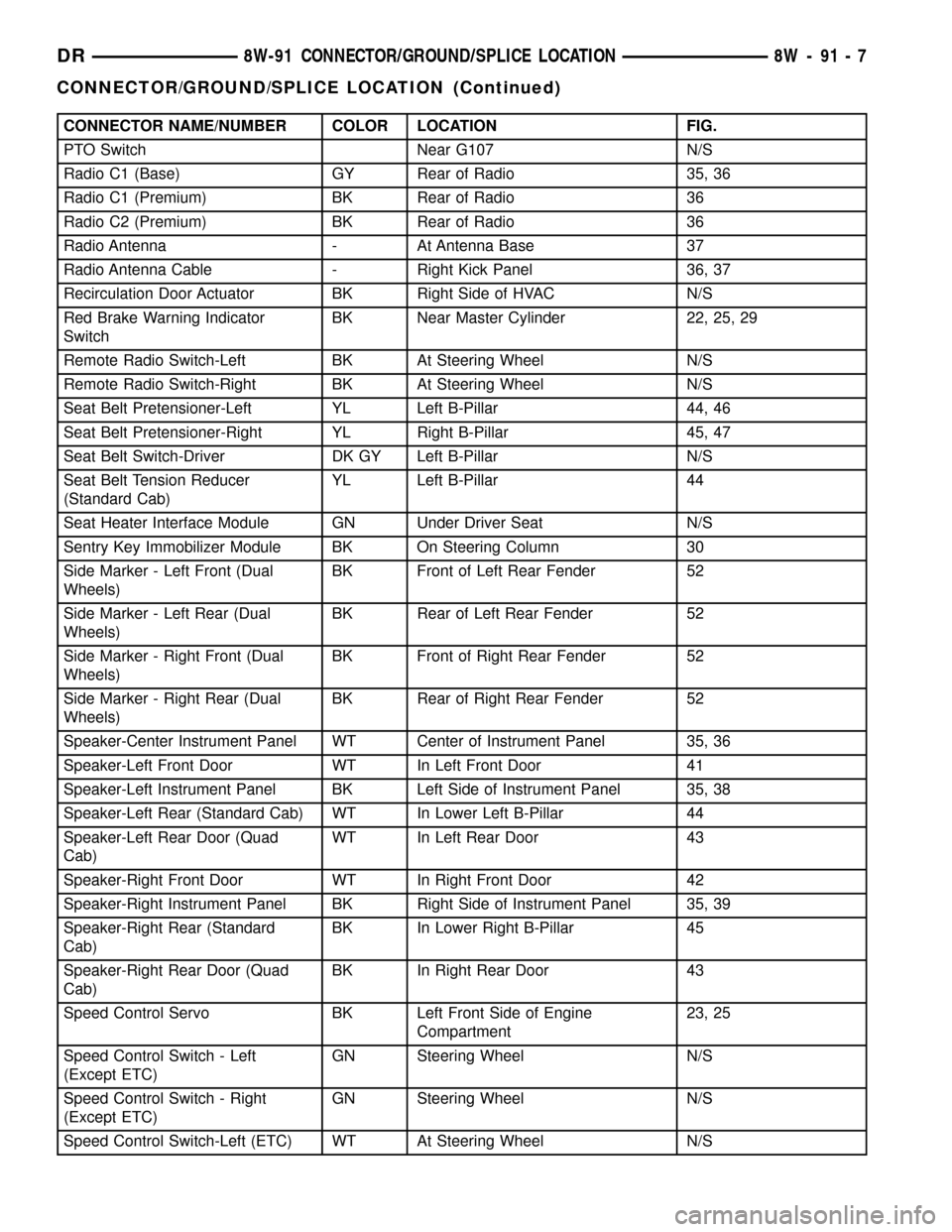
CONNECTOR NAME/NUMBER COLOR LOCATION FIG.
PTO Switch Near G107 N/S
Radio C1 (Base) GY Rear of Radio 35, 36
Radio C1 (Premium) BK Rear of Radio 36
Radio C2 (Premium) BK Rear of Radio 36
Radio Antenna - At Antenna Base 37
Radio Antenna Cable - Right Kick Panel 36, 37
Recirculation Door Actuator BK Right Side of HVAC N/S
Red Brake Warning Indicator
SwitchBK Near Master Cylinder 22, 25, 29
Remote Radio Switch-Left BK At Steering Wheel N/S
Remote Radio Switch-Right BK At Steering Wheel N/S
Seat Belt Pretensioner-Left YL Left B-Pillar 44, 46
Seat Belt Pretensioner-Right YL Right B-Pillar 45, 47
Seat Belt Switch-Driver DK GY Left B-Pillar N/S
Seat Belt Tension Reducer
(Standard Cab)YL Left B-Pillar 44
Seat Heater Interface Module GN Under Driver Seat N/S
Sentry Key Immobilizer Module BK On Steering Column 30
Side Marker - Left Front (Dual
Wheels)BK Front of Left Rear Fender 52
Side Marker - Left Rear (Dual
Wheels)BK Rear of Left Rear Fender 52
Side Marker - Right Front (Dual
Wheels)BK Front of Right Rear Fender 52
Side Marker - Right Rear (Dual
Wheels)BK Rear of Right Rear Fender 52
Speaker-Center Instrument Panel WT Center of Instrument Panel 35, 36
Speaker-Left Front Door WT In Left Front Door 41
Speaker-Left Instrument Panel BK Left Side of Instrument Panel 35, 38
Speaker-Left Rear (Standard Cab) WT In Lower Left B-Pillar 44
Speaker-Left Rear Door (Quad
Cab)WT In Left Rear Door 43
Speaker-Right Front Door WT In Right Front Door 42
Speaker-Right Instrument Panel BK Right Side of Instrument Panel 35, 39
Speaker-Right Rear (Standard
Cab)BK In Lower Right B-Pillar 45
Speaker-Right Rear Door (Quad
Cab)BK In Right Rear Door 43
Speed Control Servo BK Left Front Side of Engine
Compartment23, 25
Speed Control Switch - Left
(Except ETC)GN Steering Wheel N/S
Speed Control Switch - Right
(Except ETC)GN Steering Wheel N/S
Speed Control Switch-Left (ETC) WT At Steering Wheel N/S
DR8W-91 CONNECTOR/GROUND/SPLICE LOCATION 8W - 91 - 7
CONNECTOR/GROUND/SPLICE LOCATION (Continued)
Page 1296 of 2627

(1) Start the engine.
(2) Spray a small stream of water (spray bottle) at
the suspected leak area.
(3) If engine RPM'S change, the area of the sus-
pected leak has been found.
(4) Repair as required.
REMOVAL
(1) Disconnect negative cable from battery.
(2) Remove resonator assembly and air inlet hose.
(3) Disconnect throttle and speed control cables.
(4) Disconnect electrical connectors for the follow-
ing components: Refer to FUEL SYSTEM for compo-
nent locations.
²Manifold Absolute Pressure (MAP) Sensor
²Intake Air Temperature (IAT) Sensor
²Throttle Position (TPS) Sensor
²Coolant Temperature (CTS) Sensor
²Idle Air Control (IAC) Motor
(5) Disconnect vapor purge hose, brake booster
hose, speed control servo hose, positive crankcase
ventilation (PCV) hose.
(6) Disconnect generator electrical connections.
(7) Disconnect air conditioning compressor electri-
cal connections.
(8) Disconnect left and right radio suppressor
straps.
(9) Disconnect and remove ignition coil towers.
(10) Remove top oil dipstick tube retaining bolt
and ground strap.
(11) Bleed fuel system (Refer to 14 - FUEL SYS-
TEM/FUEL DELIVERY - STANDARD PROCE-
DURE).
(12) Remove fuel rail.
(13) Remove throttle body assembly and mounting
bracket.
(14) Drain cooling system below coolant tempera-
ture level (Refer to 7 - COOLING - STANDARD
PROCEDURE).
(15) Remove the heater hoses from the engine
front cover and the heater core.
(16) Unclip and remove heater hoses and tubes
from intake manifold.
(17) Remove coolant temperature sensor (Refer to
7 - COOLING/ENGINE/ENGINE COOLANT TEMP
SENSOR - REMOVAL).
(18) Remove intake manifold retaining fasteners in
reverse order of tightening sequence.
(19) Remove intake manifold.
INSTALLATION
(1) Install intake manifold gaskets.
(2) Install intake manifold.
(3) Install intake manifold retaining bolts and
tighten in sequence shown in to 12 N´m (105 in. lbs.)
(Fig. 89).(4) Install left and right radio suppressor straps.
(5) Install throttle body assembly.
(6) Connect throttle cable and speed control cable
to throttle body.
(7) Install fuel rail.
(8) Install ignition coil towers.
(9) Position and install heater hoses and tubes
onto intake manifold.
(10) Install the heater hoses to the heater core and
engine front cover.
(11) Connect electrical connectors for the following
components:
²Manifold Absolute Pressure (MAP) Sensor
²Intake Air Temperature (IAT) Sensor
²Throttle Position (TPS) Sensor
²Coolant Temperature (CTS) Sensor
²Idle Air Control (IAC) Motor
²Ignition coil towers
²Fuel injectors
(12) Install top oil dipstick tube retaining bolt and
ground strap.
(13) Connect generator electrical connections.
(14) Connect Vapor purge hose, Brake booster
hose, Speed control servo hose, Positive crankcase
ventilation (PCV) hose.
(15) Fill cooling system (Refer to 7 - COOLING -
STANDARD PROCEDURE).
(16) Install resonator assembly and air inlet hose.
(17) Connect negative cable to battery.
Fig. 89 Intake Manifold Tightening Sequence
DRENGINE - 3.7L 9 - 73
INTAKE MANIFOLD (Continued)
Page 1833 of 2627

AUTOMATIC TRANSMISSION - 48RE
TABLE OF CONTENTS
page page
AUTOMATIC TRANSMISSION - 48RE
DESCRIPTION........................132
OPERATION..........................134
DIAGNOSIS AND TESTING
DIAGNOSIS AND TESTING - AUTOMATIC
TRANSMISSION.....................140
DIAGNOSIS AND TESTING - PRELIMINARY . 140
DIAGNOSIS AND TESTING - ROAD
TESTING...........................140
DIAGNOSIS AND TESTING - HYDRAULIC
PRESSURE TEST....................141
DIAGNOSIS AND TESTING - AIR TESTING
TRANSMISSION CLUTCH AND BAND
OPERATION........................144
DIAGNOSIS AND TESTING - CONVERTER
HOUSING FLUID LEAK................144
DIAGNOSIS AND TESTING - DIAGNOSIS
CHARTS...........................145
STANDARD PROCEDURE - ALUMINUM
THREAD REPAIR.....................158
REMOVAL............................158
DISASSEMBLY........................160
CLEANING...........................166
INSPECTION.........................166
ASSEMBLY...........................166
INSTALLATION........................174
SCHEMATICS AND DIAGRAMS
HYDRAULIC SCHEMATICS.............176
SPECIFICATIONS
TRANSMISSION.....................189
SPECIAL TOOLS
RE TRANSMISSION..................191
ACCUMULATOR
DESCRIPTION........................193
OPERATION..........................193
INSPECTION.........................194
BANDS
DESCRIPTION........................194
OPERATION..........................194
ADJUSTMENTS
ADJUSTMENT - BANDS...............195
BRAKE TRANSMISSION SHIFT INTERLOCK
SYSTEM
DESCRIPTION........................196
OPERATION..........................196
DIAGNOSIS AND TESTING - BRAKE
TRANSMISSION SHIFT INTERLOCK......196
ADJUSTMENTS - BRAKE TRANSMISSION
SHIFT INTERLOCK...................196ELECTRONIC GOVERNOR
DESCRIPTION........................197
OPERATION..........................198
REMOVAL............................199
INSTALLATION........................200
EXTENSION HOUSING SEAL
REMOVAL............................201
INSTALLATION........................201
FLUID AND FILTER
DIAGNOSIS AND TESTING
DIAGNOSIS AND TESTING - EFFECTS OF
INCORRECT FLUID LEVEL.............201
DIAGNOSIS AND TESTING - CAUSES OF
BURNT FLUID.......................201
DIAGNOSIS AND TESTING - FLUID
CONTAMINATION....................202
STANDARD PROCEDURE
STANDARD PROCEDURE - FLUID LEVEL
CHECK............................202
STANDARD PROCEDURE - FLUID AND
FILTER REPLACEMENT...............203
STANDARD PROCEDURE - TRANSMISSION
FILL...............................204
FRONT CLUTCH
DESCRIPTION........................205
OPERATION..........................205
DISASSEMBLY........................205
INSPECTION.........................206
ASSEMBLY...........................207
FRONT SERVO
DESCRIPTION........................208
OPERATION..........................208
DISASSEMBLY........................209
CLEANING...........................209
INSPECTION.........................209
ASSEMBLY...........................209
GEARSHIFT CABLE
DIAGNOSIS AND TESTING - GEARSHIFT
CABLE.............................210
REMOVAL............................210
INSTALLATION........................211
ADJUSTMENTS
GEARSHIFT CABLE..................212
OIL PUMP
DESCRIPTION........................213
OPERATION..........................213
DISASSEMBLY........................214
CLEANING...........................214
INSPECTION.........................214
ASSEMBLY...........................214
21 - 130 AUTOMATIC TRANSMISSION - 48REDR
Page 1846 of 2627

(3) Have helper start and run engine at 1600 rpm
for test.
(4)
Move transmission shift lever four detents rear-
ward from full forward position. This is Reverse range.
(5) Move transmission throttle lever fully forward
then fully rearward and note reading at Gauge
C-3293-SP.
(6) Pressure should be 145 - 175 psi (1000-1207
kPa) with throttle lever forward and increase to 230 -
280 psi (1586-1931 kPa) as lever is gradually moved
rearward.
Test Five - Governor Pressure
This test checks governor operation by measuring
governor pressure response to changes in vehicle
speed. It is usually not necessary to check governor
operation unless shift speeds are incorrect or if the
transmission will not downshift. The test should be
performed on the road or on a hoist that will allow
the rear wheels to rotate freely.
(1) Move 100 psi Test Gauge C-3292 to governor
pressure port.
(2) Move transmission shift lever two detents rear-
ward from full forward position. This is D range.
(3) Have helper start and run engine at curb idle
speed. Then firmly apply service brakes so wheels
will not rotate.
(4) Note governor pressure:
²
Governor pressure should be no more than 20.6
kPa (3 psi) at curb idle speed and wheels not rotating.
²If pressure exceeds 20.6 kPa (3 psi), a fault
exists in governor pressure control system.
(5) Release brakes, slowly increase engine speed,
and observe speedometer and pressure test gauge (do
not exceed 30 mph on speedometer). Governor pres-
sure should increase in proportion to vehicle speed.
Or approximately 6.89 kPa (1 psi) for every 1 mph.
(6) Governor pressure rise should be smooth and
drop back to no more than 20.6 kPa (3 psi), after
engine returns to curb idle and brakes are applied to
prevent wheels from rotating.
(7)
Compare results of pressure test with analysis
chart.
Test Six - Transmission In Overdrive Fourth Gear
This test checks line pressure at the overdrive
clutch in fourth gear range. Use 300 psi Test Gauge
C-3293-SP for this test. The test should be performed
on the road or on a chassis dyno.
(1)
Remove tachometer; it is not needed for this test.
(2) Move 300 psi Gauge to overdrive clutch pres-
sure test port. Then remove other gauge and reinstall
test port plug.
(3) Lower vehicle.
(4) Turn OD switch on.(5) Secure test gauge so it can be viewed from
drivers seat.
(6) Start engine and shift into D range.
(7) Increase vehicle speed gradually until 3-4 shift
occurs and note gauge pressure.
(8) Pressure should be 524-565 kPa (76-82 psi)
with closed throttle and increase to 690-896 kPa
(100-130 psi) at 1/2 to 3/4 throttle. Note that pres-
sure can increase to around 965 kPa (140 psi) at full
throttle.
(9) Return to shop or move vehicle off chassis
dyno.
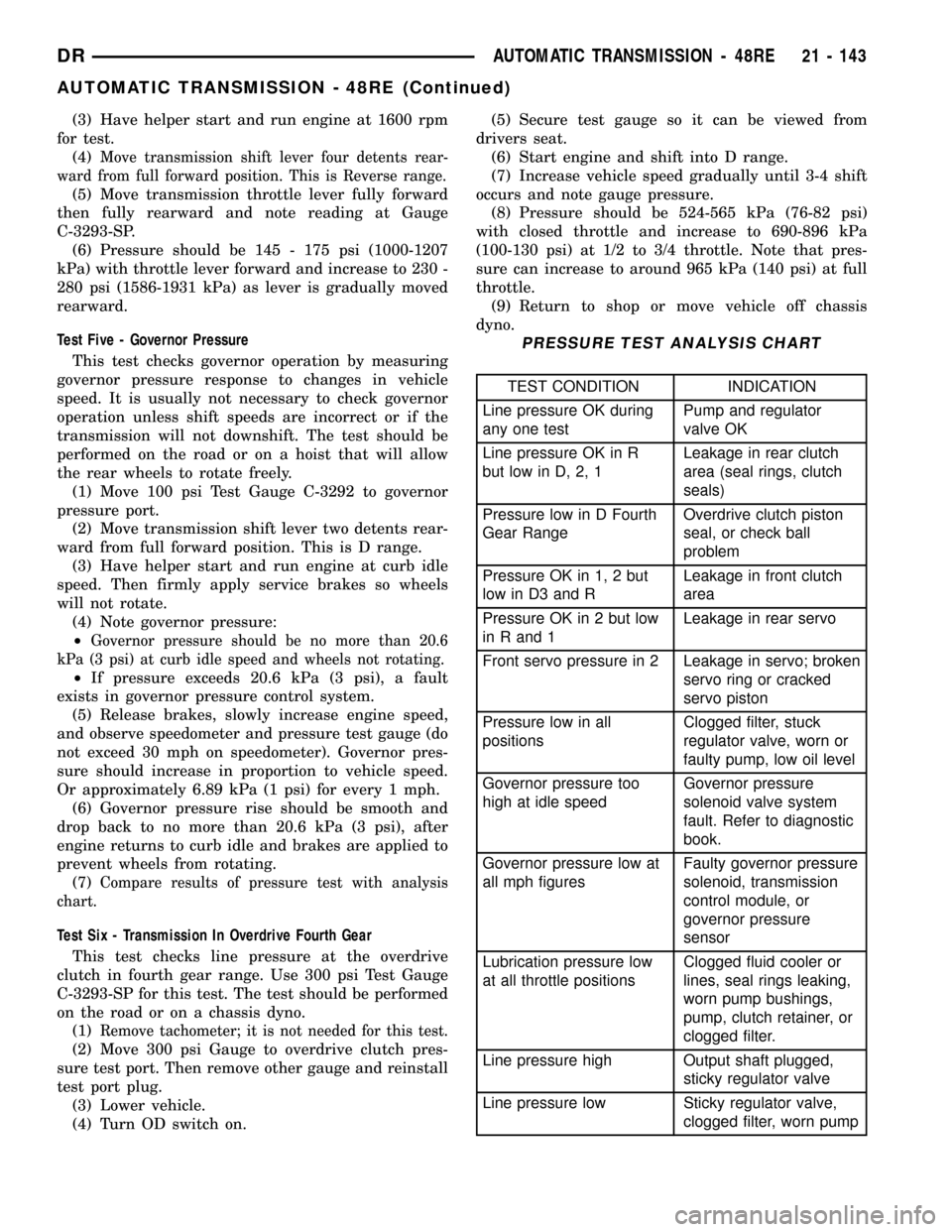
PRESSURE TEST ANALYSIS CHART
TEST CONDITION INDICATION
Line pressure OK during
any one testPump and regulator
valve OK
Line pressure OK in R
but low in D, 2, 1Leakage in rear clutch
area (seal rings, clutch
seals)
Pressure low in D Fourth
Gear RangeOverdrive clutch piston
seal, or check ball
problem
Pressure OK in 1, 2 but
low in D3 and RLeakage in front clutch
area
Pressure OK in 2 but low
in R and 1Leakage in rear servo
Front servo pressure in 2 Leakage in servo; broken
servo ring or cracked
servo piston
Pressure low in all
positionsClogged filter, stuck
regulator valve, worn or
faulty pump, low oil level
Governor pressure too
high at idle speedGovernor pressure
solenoid valve system
fault. Refer to diagnostic
book.
Governor pressure low at
all mph figuresFaulty governor pressure
solenoid, transmission
control module, or
governor pressure
sensor
Lubrication pressure low
at all throttle positionsClogged fluid cooler or
lines, seal rings leaking,
worn pump bushings,
pump, clutch retainer, or
clogged filter.
Line pressure high Output shaft plugged,
sticky regulator valve
Line pressure low Sticky regulator valve,
clogged filter, worn pump
DRAUTOMATIC TRANSMISSION - 48RE 21 - 143
AUTOMATIC TRANSMISSION - 48RE (Continued)