1998 DODGE RAM 1500 lock
[x] Cancel search: lockPage 1109 of 2627
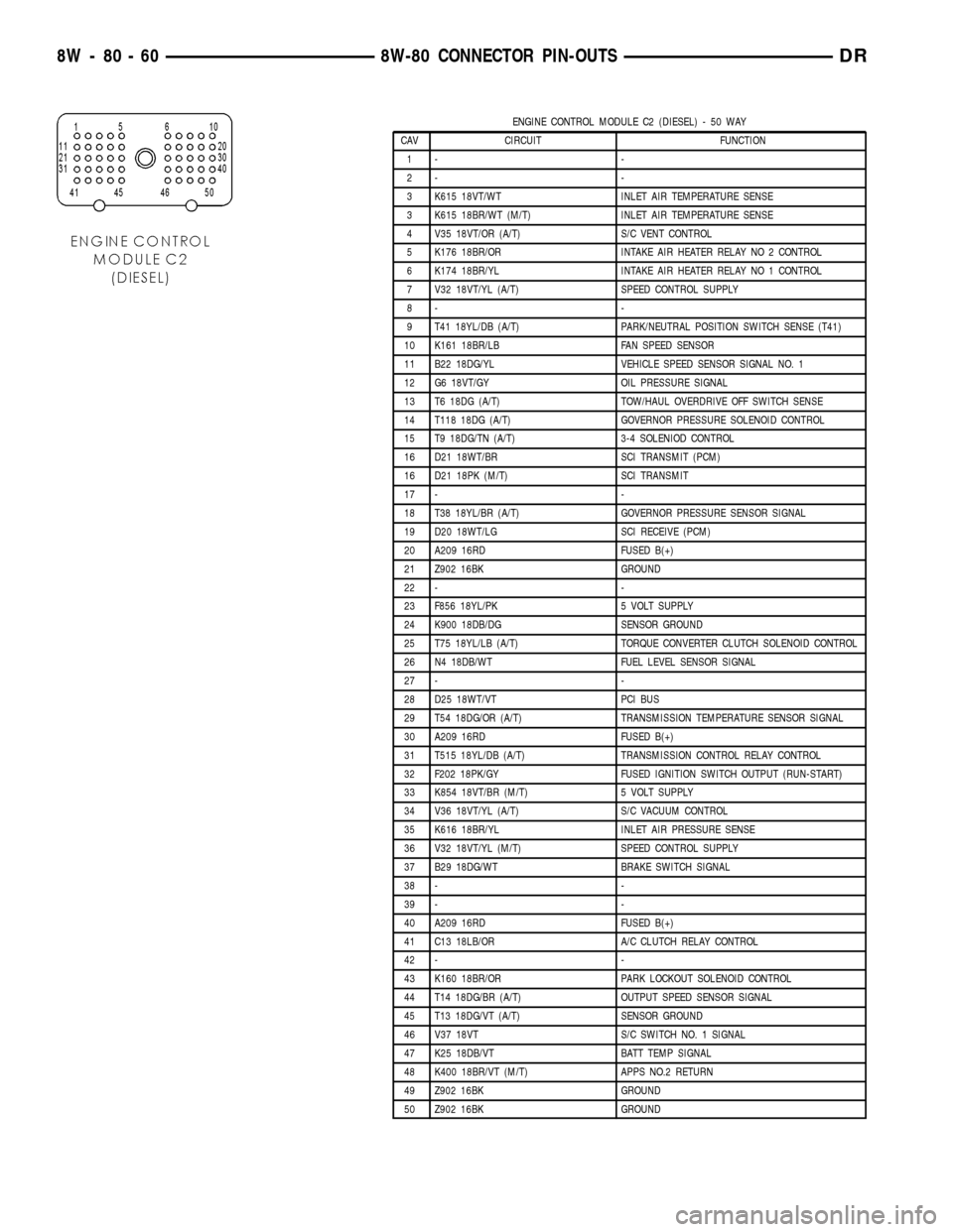
ENGINE CONTROL MODULE C2 (DIESEL) - 50 WAY
CAV CIRCUIT FUNCTION
1- -
2- -
3 K615 18VT/WT INLET AIR TEMPERATURE SENSE
3 K615 18BR/WT (M/T) INLET AIR TEMPERATURE SENSE
4 V35 18VT/OR (A/T) S/C VENT CONTROL
5 K176 18BR/OR INTAKE AIR HEATER RELAY NO 2 CONTROL
6 K174 18BR/YL INTAKE AIR HEATER RELAY NO 1 CONTROL
7 V32 18VT/YL (A/T) SPEED CONTROL SUPPLY
8- -
9 T41 18YL/DB (A/T) PARK/NEUTRAL POSITION SWITCH SENSE (T41)
10 K161 18BR/LB FAN SPEED SENSOR
11 B22 18DG/YL VEHICLE SPEED SENSOR SIGNAL NO. 1
12 G6 18VT/GY OIL PRESSURE SIGNAL
13 T6 18DG (A/T) TOW/HAUL OVERDRIVE OFF SWITCH SENSE
14 T118 18DG (A/T) GOVERNOR PRESSURE SOLENOID CONTROL
15 T9 18DG/TN (A/T) 3-4 SOLENIOD CONTROL
16 D21 18WT/BR SCI TRANSMIT (PCM)
16 D21 18PK (M/T) SCI TRANSMIT
17 - -
18 T38 18YL/BR (A/T) GOVERNOR PRESSURE SENSOR SIGNAL
19 D20 18WT/LG SCI RECEIVE (PCM)
20 A209 16RD FUSED B(+)
21 Z902 16BK GROUND
22 - -
23 F856 18YL/PK 5 VOLT SUPPLY
24 K900 18DB/DG SENSOR GROUND
25 T75 18YL/LB (A/T) TORQUE CONVERTER CLUTCH SOLENOID CONTROL
26 N4 18DB/WT FUEL LEVEL SENSOR SIGNAL
27 - -
28 D25 18WT/VT PCI BUS
29 T54 18DG/OR (A/T) TRANSMISSION TEMPERATURE SENSOR SIGNAL
30 A209 16RD FUSED B(+)
31 T515 18YL/DB (A/T) TRANSMISSION CONTROL RELAY CONTROL
32 F202 18PK/GY FUSED IGNITION SWITCH OUTPUT (RUN-START)
33 K854 18VT/BR (M/T) 5 VOLT SUPPLY
34 V36 18VT/YL (A/T) S/C VACUUM CONTROL
35 K616 18BR/YL INLET AIR PRESSURE SENSE
36 V32 18VT/YL (M/T) SPEED CONTROL SUPPLY
37 B29 18DG/WT BRAKE SWITCH SIGNAL
38 - -
39 - -
40 A209 16RD FUSED B(+)
41 C13 18LB/OR A/C CLUTCH RELAY CONTROL
42 - -
43 K160 18BR/OR PARK LOCKOUT SOLENOID CONTROL
44 T14 18DG/BR (A/T) OUTPUT SPEED SENSOR SIGNAL
45 T13 18DG/VT (A/T) SENSOR GROUND
46 V37 18VT S/C SWITCH NO. 1 SIGNAL
47 K25 18DB/VT BATT TEMP SIGNAL
48 K400 18BR/VT (M/T) APPS NO.2 RETURN
49 Z902 16BK GROUND
50 Z902 16BK GROUND
8W - 80 - 60 8W-80 CONNECTOR PIN-OUTSDR
Page 1120 of 2627
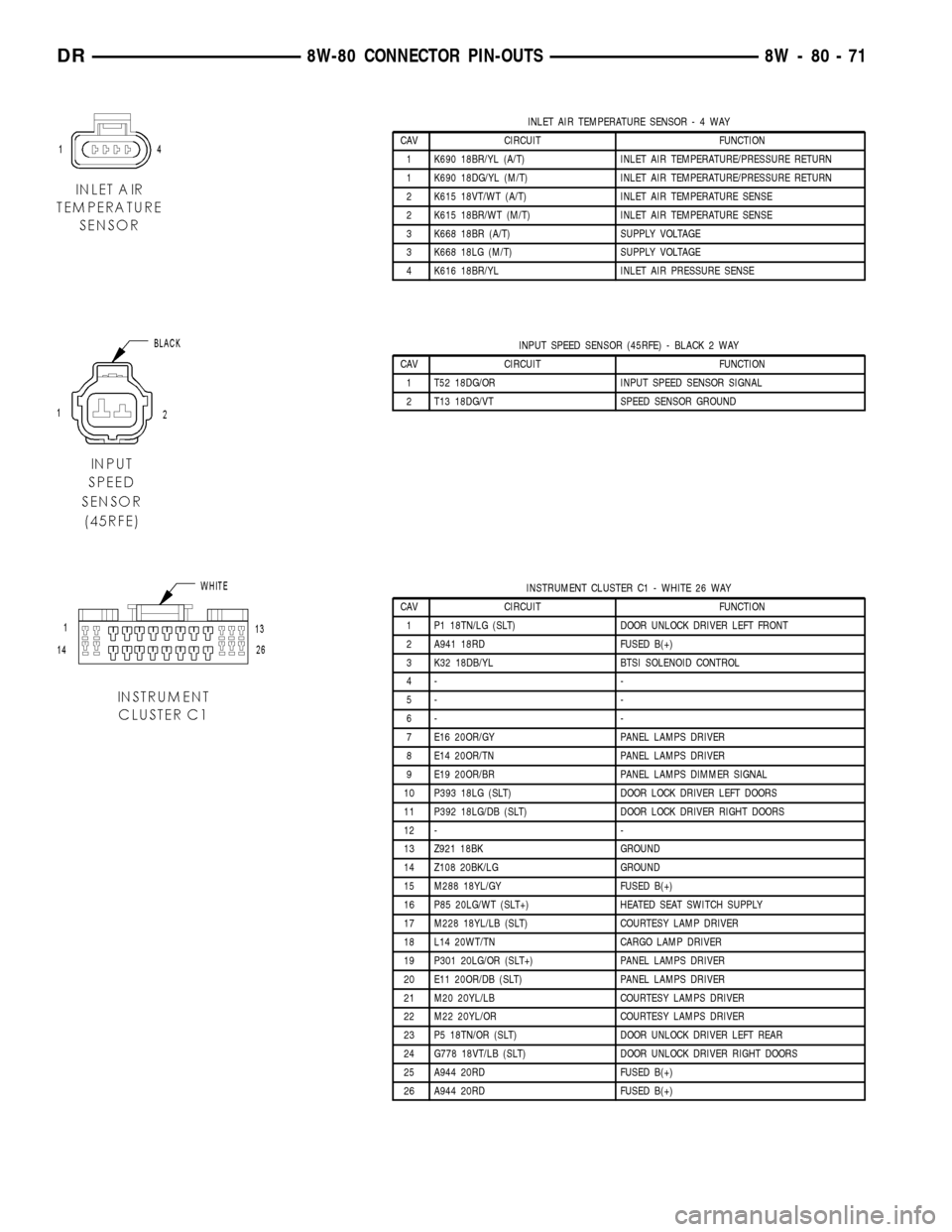
INLET AIR TEMPERATURE SENSOR-4WAY
CAV CIRCUIT FUNCTION
1 K690 18BR/YL (A/T) INLET AIR TEMPERATURE/PRESSURE RETURN
1 K690 18DG/YL (M/T) INLET AIR TEMPERATURE/PRESSURE RETURN
2 K615 18VT/WT (A/T) INLET AIR TEMPERATURE SENSE
2 K615 18BR/WT (M/T) INLET AIR TEMPERATURE SENSE
3 K668 18BR (A/T) SUPPLY VOLTAGE
3 K668 18LG (M/T) SUPPLY VOLTAGE
4 K616 18BR/YL INLET AIR PRESSURE SENSE
INPUT SPEED SENSOR (45RFE) - BLACK 2 WAY
CAV CIRCUIT FUNCTION
1 T52 18DG/OR INPUT SPEED SENSOR SIGNAL
2 T13 18DG/VT SPEED SENSOR GROUND
INSTRUMENT CLUSTER C1 - WHITE 26 WAY
CAV CIRCUIT FUNCTION
1 P1 18TN/LG (SLT) DOOR UNLOCK DRIVER LEFT FRONT
2 A941 18RD FUSED B(+)
3 K32 18DB/YL BTSI SOLENOID CONTROL
4- -
5- -
6- -
7 E16 20OR/GY PANEL LAMPS DRIVER
8 E14 20OR/TN PANEL LAMPS DRIVER
9 E19 20OR/BR PANEL LAMPS DIMMER SIGNAL
10 P393 18LG (SLT) DOOR LOCK DRIVER LEFT DOORS
11 P392 18LG/DB (SLT) DOOR LOCK DRIVER RIGHT DOORS
12 - -
13 Z921 18BK GROUND
14 Z108 20BK/LG GROUND
15 M288 18YL/GY FUSED B(+)
16 P85 20LG/WT (SLT+) HEATED SEAT SWITCH SUPPLY
17 M228 18YL/LB (SLT) COURTESY LAMP DRIVER
18 L14 20WT/TN CARGO LAMP DRIVER
19 P301 20LG/OR (SLT+) PANEL LAMPS DRIVER
20 E11 20OR/DB (SLT) PANEL LAMPS DRIVER
21 M20 20YL/LB COURTESY LAMPS DRIVER
22 M22 20YL/OR COURTESY LAMPS DRIVER
23 P5 18TN/OR (SLT) DOOR UNLOCK DRIVER LEFT REAR
24 G778 18VT/LB (SLT) DOOR UNLOCK DRIVER RIGHT DOORS
25 A944 20RD FUSED B(+)
26 A944 20RD FUSED B(+)
DR8W-80 CONNECTOR PIN-OUTS 8W - 80 - 71
Page 1121 of 2627
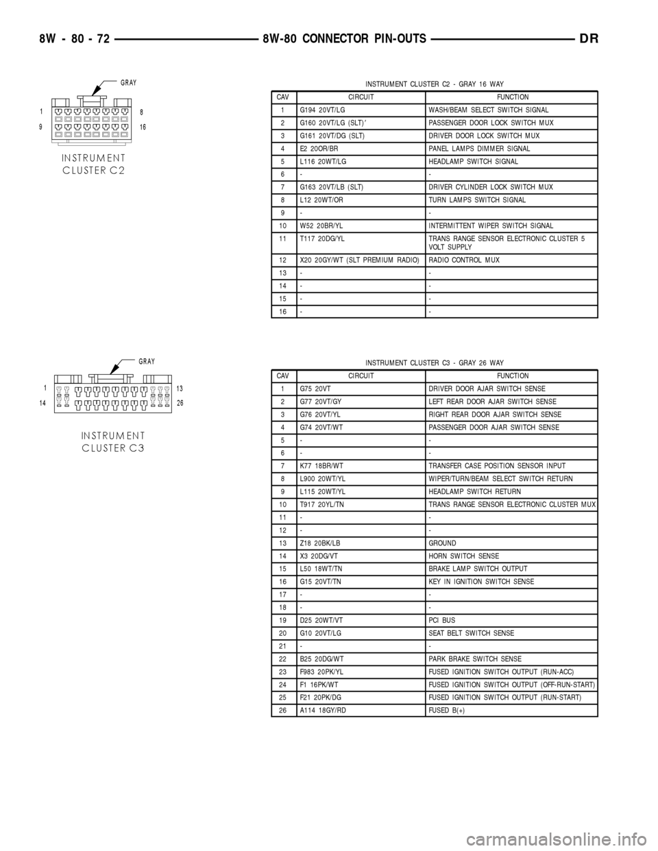
INSTRUMENT CLUSTER C2 - GRAY 16 WAY
CAV CIRCUIT FUNCTION
1 G194 20VT/LG WASH/BEAM SELECT SWITCH SIGNAL
2 G160 20VT/LG (SLT)8PASSENGER DOOR LOCK SWITCH MUX
3 G161 20VT/DG (SLT) DRIVER DOOR LOCK SWITCH MUX
4 E2 20OR/BR PANEL LAMPS DIMMER SIGNAL
5 L116 20WT/LG HEADLAMP SWITCH SIGNAL
6- -
7 G163 20VT/LB (SLT) DRIVER CYLINDER LOCK SWITCH MUX
8 L12 20WT/OR TURN LAMPS SWITCH SIGNAL
9- -
10 W52 20BR/YL INTERMITTENT WIPER SWITCH SIGNAL
11 T117 20DG/YL TRANS RANGE SENSOR ELECTRONIC CLUSTER 5
VOLT SUPPLY
12 X20 20GY/WT (SLT PREMIUM RADIO) RADIO CONTROL MUX
13 - -
14 - -
15 - -
16 - -
INSTRUMENT CLUSTER C3 - GRAY 26 WAY
CAV CIRCUIT FUNCTION
1 G75 20VT DRIVER DOOR AJAR SWITCH SENSE
2 G77 20VT/GY LEFT REAR DOOR AJAR SWITCH SENSE
3 G76 20VT/YL RIGHT REAR DOOR AJAR SWITCH SENSE
4 G74 20VT/WT PASSENGER DOOR AJAR SWITCH SENSE
5- -
6- -
7 K77 18BR/WT TRANSFER CASE POSITION SENSOR INPUT
8 L900 20WT/YL WIPER/TURN/BEAM SELECT SWITCH RETURN
9 L115 20WT/YL HEADLAMP SWITCH RETURN
10 T917 20YL/TN TRANS RANGE SENSOR ELECTRONIC CLUSTER MUX
11 - -
12 - -
13 Z18 20BK/LB GROUND
14 X3 20DG/VT HORN SWITCH SENSE
15 L50 18WT/TN BRAKE LAMP SWITCH OUTPUT
16 G15 20VT/TN KEY IN IGNITION SWITCH SENSE
17 - -
18 - -
19 D25 20WT/VT PCI BUS
20 G10 20VT/LG SEAT BELT SWITCH SENSE
21 - -
22 B25 20DG/WT PARK BRAKE SWITCH SENSE
23 F983 20PK/YL FUSED IGNITION SWITCH OUTPUT (RUN-ACC)
24 F1 16PK/WT FUSED IGNITION SWITCH OUTPUT (OFF-RUN-START)
25 F21 20PK/DG FUSED IGNITION SWITCH OUTPUT (RUN-START)
26 A114 18GY/RD FUSED B(+)
8W - 80 - 72 8W-80 CONNECTOR PIN-OUTSDR
Page 1152 of 2627
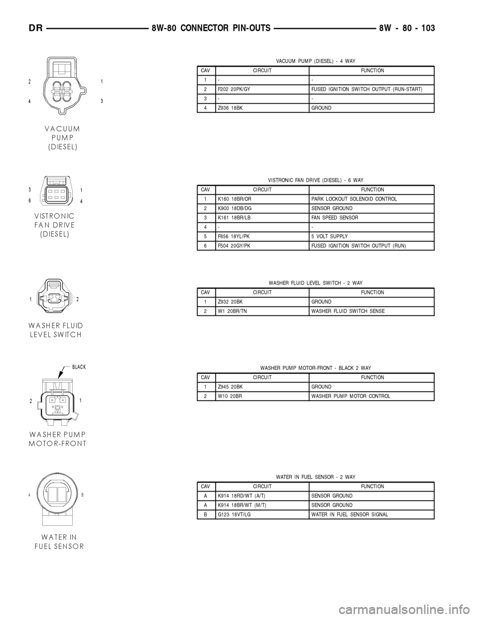
VACUUM PUMP (DIESEL)-4WAY
CAV CIRCUIT FUNCTION
1- -
2 F202 20PK/GY FUSED IGNITION SWITCH OUTPUT (RUN-START)
3- -
4 Z936 18BK GROUND
VISTRONIC FAN DRIVE (DIESEL)-6WAY
CAV CIRCUIT FUNCTION
1 K160 18BR/OR PARK LOCKOUT SOLENOID CONTROL
2 K900 18DB/DG SENSOR GROUND
3 K161 18BR/LB FAN SPEED SENSOR
4- -
5 F856 18YL/PK 5 VOLT SUPPLY
6 F504 20GY/PK FUSED IGNITION SWITCH OUTPUT (RUN)
WASHER FLUID LEVEL SWITCH-2WAY
CAV CIRCUIT FUNCTION
1 Z932 20BK GROUND
2 W1 20BR/TN WASHER FLUID SWITCH SENSE
WASHER PUMP MOTOR-FRONT - BLACK 2 WAY
CAV CIRCUIT FUNCTION
1 Z945 20BK GROUND
2 W10 20BR WASHER PUMP MOTOR CONTROL
WATER IN FUEL SENSOR-2WAY
CAV CIRCUIT FUNCTION
A K914 18RD/WT (A/T) SENSOR GROUND
A K914 18BR/WT (M/T) SENSOR GROUND
B G123 18VT/LG WATER IN FUEL SENSOR SIGNAL
DR8W-80 CONNECTOR PIN-OUTS 8W - 80 - 103
Page 1155 of 2627
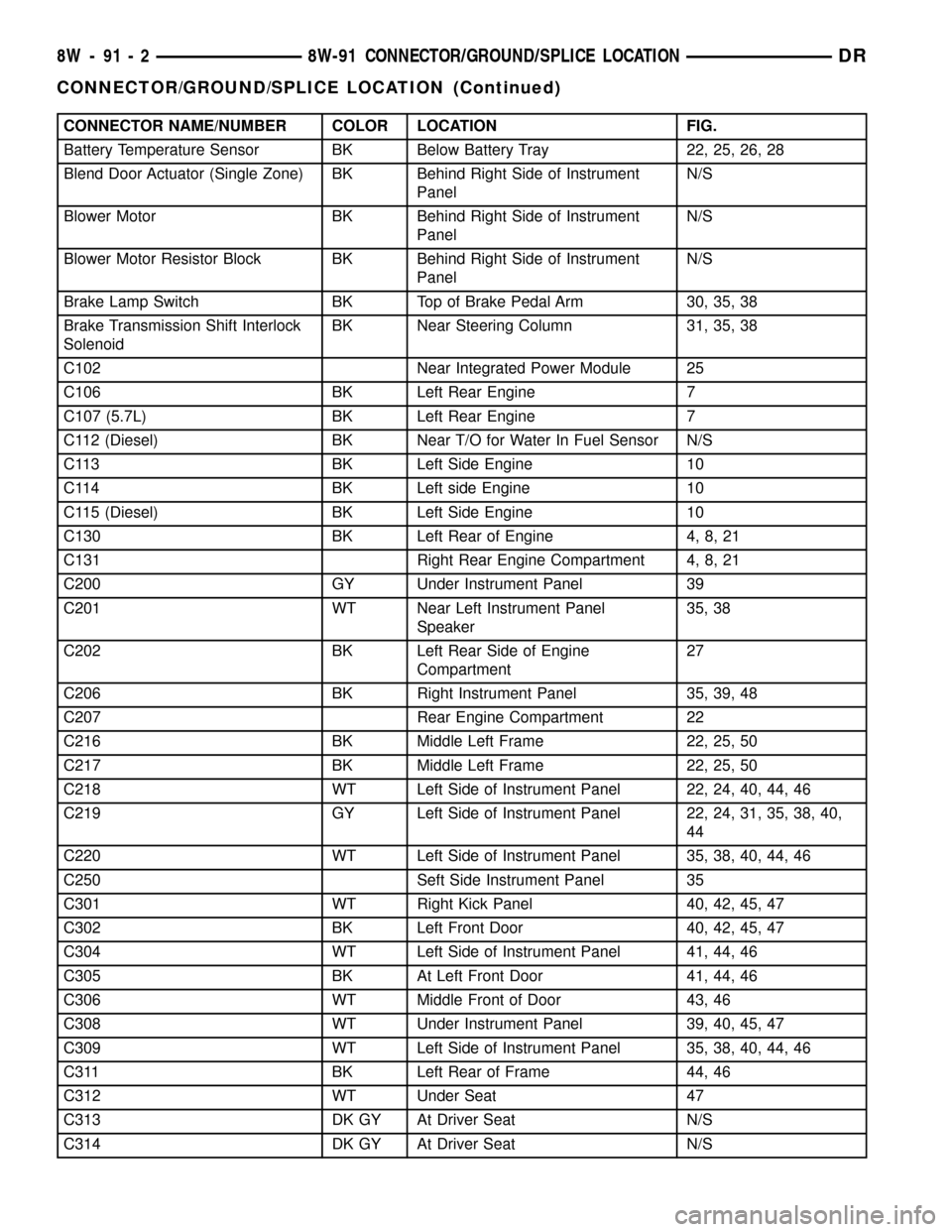
CONNECTOR NAME/NUMBER COLOR LOCATION FIG.
Battery Temperature Sensor BK Below Battery Tray 22, 25, 26, 28
Blend Door Actuator (Single Zone) BK Behind Right Side of Instrument
PanelN/S
Blower Motor BK Behind Right Side of Instrument
PanelN/S
Blower Motor Resistor Block BK Behind Right Side of Instrument
PanelN/S
Brake Lamp Switch BK Top of Brake Pedal Arm 30, 35, 38
Brake Transmission Shift Interlock
SolenoidBK Near Steering Column 31, 35, 38
C102 Near Integrated Power Module 25
C106 BK Left Rear Engine 7
C107 (5.7L) BK Left Rear Engine 7
C112 (Diesel) BK Near T/O for Water In Fuel Sensor N/S
C113 BK Left Side Engine 10
C114 BK Left side Engine 10
C115 (Diesel) BK Left Side Engine 10
C130 BK Left Rear of Engine 4, 8, 21
C131 Right Rear Engine Compartment 4, 8, 21
C200 GY Under Instrument Panel 39
C201 WT Near Left Instrument Panel
Speaker35, 38
C202 BK Left Rear Side of Engine
Compartment27
C206 BK Right Instrument Panel 35, 39, 48
C207 Rear Engine Compartment 22
C216 BK Middle Left Frame 22, 25, 50
C217 BK Middle Left Frame 22, 25, 50
C218 WT Left Side of Instrument Panel 22, 24, 40, 44, 46
C219 GY Left Side of Instrument Panel 22, 24, 31, 35, 38, 40,
44
C220 WT Left Side of Instrument Panel 35, 38, 40, 44, 46
C250 Seft Side Instrument Panel 35
C301 WT Right Kick Panel 40, 42, 45, 47
C302 BK Left Front Door 40, 42, 45, 47
C304 WT Left Side of Instrument Panel 41, 44, 46
C305 BK At Left Front Door 41, 44, 46
C306 WT Middle Front of Door 43, 46
C308 WT Under Instrument Panel 39, 40, 45, 47
C309 WT Left Side of Instrument Panel 35, 38, 40, 44, 46
C311 BK Left Rear of Frame 44, 46
C312 WT Under Seat 47
C313 DK GY At Driver Seat N/S
C314 DK GY At Driver Seat N/S
8W - 91 - 2 8W-91 CONNECTOR/GROUND/SPLICE LOCATIONDR
CONNECTOR/GROUND/SPLICE LOCATION (Continued)
Page 1156 of 2627
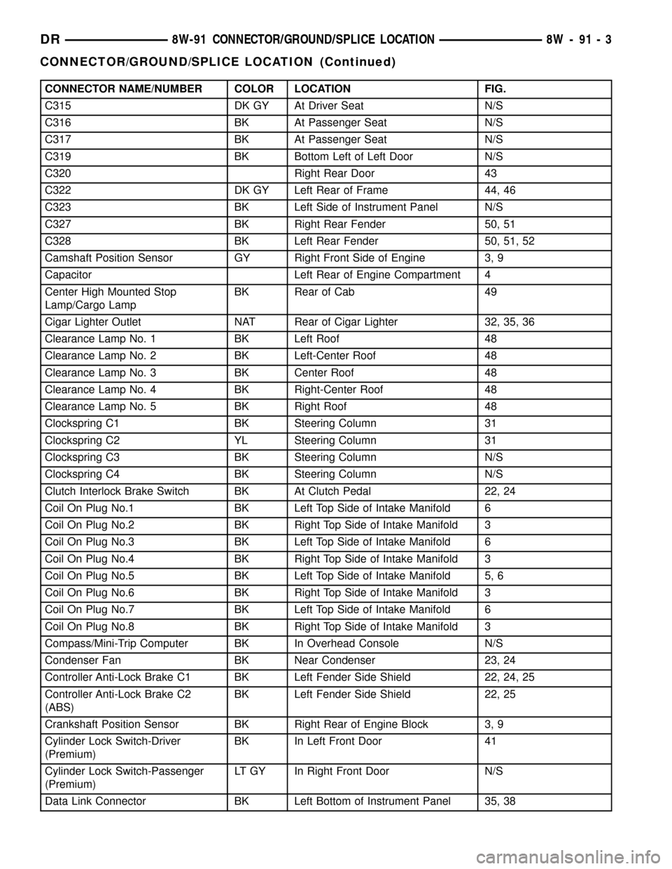
CONNECTOR NAME/NUMBER COLOR LOCATION FIG.
C315 DK GY At Driver Seat N/S
C316 BK At Passenger Seat N/S
C317 BK At Passenger Seat N/S
C319 BK Bottom Left of Left Door N/S
C320 Right Rear Door 43
C322 DK GY Left Rear of Frame 44, 46
C323 BK Left Side of Instrument Panel N/S
C327 BK Right Rear Fender 50, 51
C328 BK Left Rear Fender 50, 51, 52
Camshaft Position Sensor GY Right Front Side of Engine 3, 9
Capacitor Left Rear of Engine Compartment 4
Center High Mounted Stop
Lamp/Cargo LampBK Rear of Cab 49
Cigar Lighter Outlet NAT Rear of Cigar Lighter 32, 35, 36
Clearance Lamp No. 1 BK Left Roof 48
Clearance Lamp No. 2 BK Left-Center Roof 48
Clearance Lamp No. 3 BK Center Roof 48
Clearance Lamp No. 4 BK Right-Center Roof 48
Clearance Lamp No. 5 BK Right Roof 48
Clockspring C1 BK Steering Column 31
Clockspring C2 YL Steering Column 31
Clockspring C3 BK Steering Column N/S
Clockspring C4 BK Steering Column N/S
Clutch Interlock Brake Switch BK At Clutch Pedal 22, 24
Coil On Plug No.1 BK Left Top Side of Intake Manifold 6
Coil On Plug No.2 BK Right Top Side of Intake Manifold 3
Coil On Plug No.3 BK Left Top Side of Intake Manifold 6
Coil On Plug No.4 BK Right Top Side of Intake Manifold 3
Coil On Plug No.5 BK Left Top Side of Intake Manifold 5, 6
Coil On Plug No.6 BK Right Top Side of Intake Manifold 3
Coil On Plug No.7 BK Left Top Side of Intake Manifold 6
Coil On Plug No.8 BK Right Top Side of Intake Manifold 3
Compass/Mini-Trip Computer BK In Overhead Console N/S
Condenser Fan BK Near Condenser 23, 24
Controller Anti-Lock Brake C1 BK Left Fender Side Shield 22, 24, 25
Controller Anti-Lock Brake C2
(ABS)BK Left Fender Side Shield 22, 25
Crankshaft Position Sensor BK Right Rear of Engine Block 3, 9
Cylinder Lock Switch-Driver
(Premium)BK In Left Front Door 41
Cylinder Lock Switch-Passenger
(Premium)LT GY In Right Front Door N/S
Data Link Connector BK Left Bottom of Instrument Panel 35, 38
DR8W-91 CONNECTOR/GROUND/SPLICE LOCATION 8W - 91 - 3
CONNECTOR/GROUND/SPLICE LOCATION (Continued)
Page 1157 of 2627
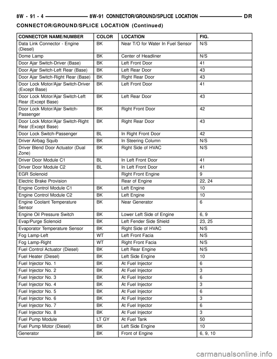
CONNECTOR NAME/NUMBER COLOR LOCATION FIG.
Data Link Connector - Engine
(Diesel)BK Near T/O for Water In Fuel Sensor N/S
Dome Lamp BK Center of Headliner N/S
Door Ajar Switch-Driver (Base) BK Left Front Door 41
Door Ajar Switch-Left Rear (Base) BK Left Rear Door 43
Door Ajar Switch-Right Rear (Base) BK Right Rear Door 43
Door Lock Motor/Ajar Switch-Driver
(Except Base)BK Left Front Door 41
Door Lock Motor/Ajar Switch-Left
Rear (Except Base)BK Left Rear Door 43
Door Lock Motor/Ajar Switch-
PassengerBK Right Front Door 42
Door Lock Motor/Ajar Switch-Right
Rear (Except Base)BK Right Rear Door 43
Door Lock Switch-Passenger BL In Right Front Door 42
Driver Airbag Squib BK In Steering Column N/S
Driver Blend Door Actuator (Dual
Zone)BK Right Side of HVAC N/S
Driver Door Module C1 BL In Left Front Door 41
Driver Door Module C2 BL In Left Front Door 41
EGR Solenoid Right Front Engine 9
Electric Brake Provision Rear of Engine 22, 24
Engine Control Module C1 BK Left Engine 10
Engine Control Module C2 BK Left Engine 10
Engine Coolant Temperature
SensorBK Near Generator 6
Engine Oil Pressure Switch BK Lower Left Side of Engine 6, 9
Evap/Purge Solenoid BK Left Fender Side Shield 23, 25
Evaporator Temperature Sensor BK Right Side of HVAC N/S
Fog Lamp-Left WT Left Front Facia N/S
Fog Lamp-Right WT Right Front Facia N/S
Fuel Control Actuator (Diesel) BK Left Rear Engine N/S
Fuel Heater (Diesel) BK Left Side Engine 10
Fuel Injector No. 1 BK At Fuel Injector 6
Fuel Injector No. 2 BK At Fuel Injector 3
Fuel Injector No. 3 BK At Fuel Injector 6
Fuel Injector No. 4 BK At Fuel Injector 3
Fuel Injector No. 5 BK At Fuel Injector 6
Fuel Injector No. 6 BK At Fuel Injector 3
Fuel Injector No. 7 BK At Fuel Injector 6
Fuel Injector No. 8 BK At Fuel Injector 3
Fuel Pump Module LT GY At Fuel Tank 50
Fuel Pump Motor (Diesel) BK Left Side Engine 10
Generator BK Front of Engine 6, 9, 10
8W - 91 - 4 8W-91 CONNECTOR/GROUND/SPLICE LOCATIONDR
CONNECTOR/GROUND/SPLICE LOCATION (Continued)
Page 1217 of 2627

SPECIAL TOOLS
POWER DISTRIBUTION SYSTEMS
CIGAR LIGHTER OUTLET
DESCRIPTION
On models equipped a cigar lighter outlet is
installed to the left of the center stack area in the
lower instrument panel. The cigar lighter outlet is
secured by a snap fit within the bezel.
The cigar lighter outlet, plastic cap and the knob
and heating element unit are available for service
replacement. These components cannot be repaired
and, if faulty or damaged, they must be replaced.
OPERATION
The cigar lighter consists of two major components:
a knob and heating element unit, and the cigar
lighter base or outlet shell. The receptacle shell is
connected to ground, and an insulated contact in the
bottom of the shell is connected to battery current.
The cigar lighter receives battery voltage from a fuse
in the junction block when the ignition switch is in
the Accessory or Run positions.
The cigar lighter knob and heating element are
encased within a spring-loaded housing, which also
features a sliding protective heat shield. When the
knob and heating element are inserted in the outlet
shell, the heating element resistor coil is grounded
through its housing to the outlet shell. If the cigar
lighter knob is pushed inward, the heat shield slides
up toward the knob exposing the heating element,
and the heating element extends from the housing
toward the insulated contact in the bottom of the
outlet shell.
Two small spring-clip retainers are located on
either side of the insulated contact inside the bottom
of the outlet shell. These clips engage and hold the
heating element against the insulated contact longenough for the resistor coil to heat up. When the
heating element is engaged with the contact, battery
current can flow through the resistor coil to ground,
causing the resistor coil to heat.
When the resistor coil becomes sufficiently heated,
excess heat radiates from the heating element caus-
ing the spring-clips to expand. Once the spring-clips
expand far enough to release the heating element,
the spring-loaded housing forces the knob and heat-
ing element to pop back outward to their relaxed
position. When the cigar lighter knob and element
are pulled out of the outlet shell, the protective heat
shield slides downward on the housing so that the
heating element is recessed and shielded around its
circumference for safety.
DIAGNOSIS AND TESTING - CIGAR LIGHTER
OUTLET
For complete circuit diagrams, refer toWiring
Diagrams.
(1) Check the fused B(+) fuse in the integrated
power module. If OK, go to Step 2. If not OK, repair
the shorted circuit or component as required and
replace the faulty fuse.
(2) Turn the ignition switch to the Run position.
Check for battery voltage at the fused B(+) fuse in
the integrated power module. If OK, go to Step 3. If
not OK, repair the open or short as required.
(3) Remove the cigar lighter knob and element
from the cigar lighter outlet shell. Check for continu-
ity between the inside circumference of the cigar
lighter outlet shell and a good ground. there should
be continuity. If OK, go to Step 4. If not OK, go to
Step 5.
(4) Turn the ignition switch to the Run position.
Check for battery voltage at the insulated contact
located at the back of the cigar lighter outlet shell. If
OK, replace the faulty cigar lighter knob and ele-
ment. If not OK, go to Step 5.
(5) Turn the ignition switch to the Off position.
Disconnect and isolate the battery negative cable.
Check for continuity between the ground circuit cav-
ity of the cigar lighter wire harness connector and a
good ground. There should be continuity. If OK, go to
Step 6. If not OK, repair the open ground circuit to
ground as required.
(6) Connect the battery negative cable. Turn the
ignition switch to the Accessory or Run positions.
Check for battery voltage at the fused B(+) circuit
cavity of the cigar lighter wire harness connector. If
OK, replace the faulty cigar lighter outlet. If not OK,
repair the open fused B(+) circuit to the integrated
power module fuse as required.Terminal Pick Kit 6680
8W - 97 - 2 8W-97 POWER DISTRIBUTIONDR
POWER DISTRIBUTION (Continued)