Page 1755 of 2627

MAINSHAFT AND GEARTRAIN
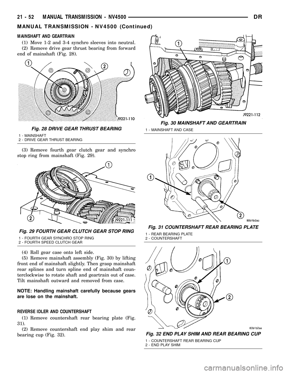
(1) Move 1-2 and 3-4 synchro sleeves into neutral.
(2) Remove drive gear thrust bearing from forward
end of mainshaft (Fig. 28).
(3) Remove fourth gear clutch gear and synchro
stop ring from mainshaft (Fig. 29).
(4) Roll gear case onto left side.
(5) Remove mainshaft assembly (Fig. 30) by lifting
front end of mainshaft slightly. Then grasp mainshaft
rear splines and turn spline end of mainshaft coun-
terclockwise to rotate shaft and geartrain out of case.
Tilt mainshaft outward and removed from case.
NOTE: Handling mainshaft carefully because gears
are lose on the mainshaft.
REVERSE IDLER AND COUNTERSHAFT
(1) Remove countershaft rear bearing plate (Fig.
31).
(2) Remove countershaft end play shim and rear
bearing cup (Fig. 32).
Fig. 28 DRIVE GEAR THRUST BEARING
1 - MAINSHAFT
2 - DRIVE GEAR THRUST BEARING
Fig. 29 FOURTH GEAR CLUTCH GEAR STOP RING
1 - FOURTH GEAR SYNCHRO STOP RING
2 - FOURTH SPEED CLUTCH GEAR
Fig. 30 MAINSHAFT AND GEARTRAIN
1 - MAINSHAFT AND CASE
Fig. 31 COUNTERSHAFT REAR BEARING PLATE
1 - REAR BEARING PLATE
2 - COUNTERSHAFT
Fig. 32 END PLAY SHIM AND REAR BEARING CUP
1 - COUNTERSHAFT REAR BEARING CUP
2 - END PLAY SHIM
21 - 52 MANUAL TRANSMISSION - NV4500DR
MANUAL TRANSMISSION - NV4500 (Continued)
Page 1756 of 2627
(3) Remove reverse idler shaft (Fig. 33).
(4) Rotate countershaft outward and push reverse
idler gear away from countershaft and toward front
of case (Fig. 34).(5) Remove idler gear (Fig. 35).
(6) Keep reverse idler gear bearings and spacer
together (Fig. 36). Insert idler shaft through gear and
bearings to keep them in place.
(7) Remove idler gear thrust washers from gear
case. Install washers on idler shaft to keep them
together for cleaning and inspection.
Fig. 33 REVERSE IDLER SHAFT
1 - REVERSE IDLER SHAFT
Fig. 34 IDLER GEAR AND COUNTERSHAFT
1 - REVERSE IDLER GEAR
2 - COUNTERSHAFT
Fig. 35 REVERSE IDLER GEAR
1 - REVERSE IDLER GEAR
2 - DRIVE GEAR BORE
Fig. 36 IDLER GEAR COMPONENTS
1 - BEARINGS
2 - REVERSE IDLER GEAR
DRMANUAL TRANSMISSION - NV4500 21 - 53
MANUAL TRANSMISSION - NV4500 (Continued)
Page 1757 of 2627

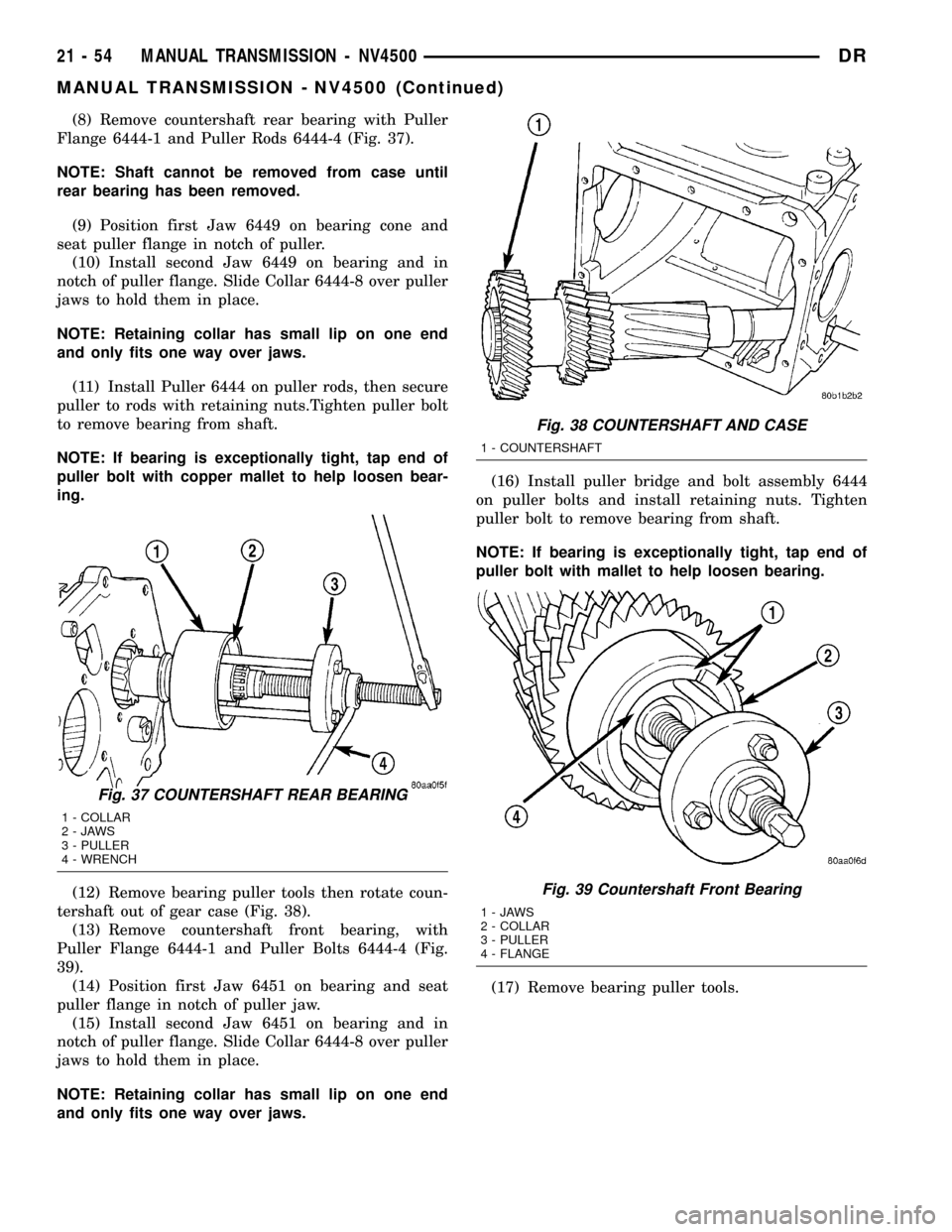
(8) Remove countershaft rear bearing with Puller
Flange 6444-1 and Puller Rods 6444-4 (Fig. 37).
NOTE: Shaft cannot be removed from case until
rear bearing has been removed.
(9) Position first Jaw 6449 on bearing cone and
seat puller flange in notch of puller.
(10) Install second Jaw 6449 on bearing and in
notch of puller flange. Slide Collar 6444-8 over puller
jaws to hold them in place.
NOTE: Retaining collar has small lip on one end
and only fits one way over jaws.
(11) Install Puller 6444 on puller rods, then secure
puller to rods with retaining nuts.Tighten puller bolt
to remove bearing from shaft.
NOTE: If bearing is exceptionally tight, tap end of
puller bolt with copper mallet to help loosen bear-
ing.
(12) Remove bearing puller tools then rotate coun-
tershaft out of gear case (Fig. 38).
(13) Remove countershaft front bearing, with
Puller Flange 6444-1 and Puller Bolts 6444-4 (Fig.
39).
(14) Position first Jaw 6451 on bearing and seat
puller flange in notch of puller jaw.
(15) Install second Jaw 6451 on bearing and in
notch of puller flange. Slide Collar 6444-8 over puller
jaws to hold them in place.
NOTE: Retaining collar has small lip on one end
and only fits one way over jaws.(16) Install puller bridge and bolt assembly 6444
on puller bolts and install retaining nuts. Tighten
puller bolt to remove bearing from shaft.
NOTE: If bearing is exceptionally tight, tap end of
puller bolt with mallet to help loosen bearing.
(17) Remove bearing puller tools.
Fig. 37 COUNTERSHAFT REAR BEARING
1 - COLLAR
2-JAWS
3 - PULLER
4 - WRENCH
Fig. 38 COUNTERSHAFT AND CASE
1 - COUNTERSHAFT
Fig. 39 Countershaft Front Bearing
1-JAWS
2 - COLLAR
3 - PULLER
4 - FLANGE
21 - 54 MANUAL TRANSMISSION - NV4500DR
MANUAL TRANSMISSION - NV4500 (Continued)
Page 1758 of 2627
GEAR CASE
(1) Remove countershaft front bearing cap with
hammer (Fig. 40).
(2) Remove countershaft front bearing cup with
Remover 6454 and Handle C-4171 (Fig. 41).(3) Remove roll pin that secures shift lug on shift
rail in case (Fig. 42). A small pin punch can be mod-
ified by putting a slight bend in it to drive pin com-
pletely out of shift rail (Fig. 42).
(4) Remove shift lug rail.
Fig. 40 COUNTERSHAFT FRONT BEARING CAP
1 - HAMMER
2 - BEARING CAP
Fig. 41 COUNTERSHAFT FRONT BEARING CUP
1 - REMOVER
2 - HANDLE
Fig. 42 SHIFT LUG ROLL PIN
1 - PUNCH
2 - 30É BEND
3 - PIN PUNCH MODIFICATION
4 - SHIFT LUG
5 - SHIFT RAIL
DRMANUAL TRANSMISSION - NV4500 21 - 55
MANUAL TRANSMISSION - NV4500 (Continued)
Page 1759 of 2627
MAINSHAFT
NOTE: Gear and synchro components can be
installed backwards. Paint or scribe gear and syn-
chro components for installation reference. Then
stack geartrain parts in order of removal.
(1) Remove drive gear thrust bearing from end of
mainshaft, if not previously removed.
(2) Place 3-4 gear in a press with support under
3rd gear and Remove 3-4 synchro hub, third gear
stop ring and third gear as an assembly (Fig. 43).
(3) Remove third gear bearing from mainshaft
(Fig. 44).
(4) Remove third gear bearing spacer (Fig. 45).
(5) Remove second gear thrust washer snap ring
from mainshaft (Fig. 45).
Fig. 43 THIRD GEAR, STOP RING, AND 3-4 HUB
1 - THIRD GEAR
2 - THIRD GEAR STOP RING
3 - 3-4 SYNCHRO HUB
Fig. 44 THIRD GEAR BEARING
1 - THIRD GEAR NEEDLE BEARING
Fig. 45 SNAP RING AND THIRD GEAR BEARING
SPACER
1 - SECOND GEAR THRUST WASHER
2 - THRUST WASHER SNAP RING
3 - THIRD GEAR BEARING SPACER
21 - 56 MANUAL TRANSMISSION - NV4500DR
MANUAL TRANSMISSION - NV4500 (Continued)
Page 1760 of 2627
(6) Remove second gear thrust washer (Fig. 46).
Note washer notch for locating pin.
(7) Remove thrust washer locating pin (Fig. 47)
with needle nose pliers.(8) Remove second gear (Fig. 48).
(9) Remove second gear bearing (Fig. 49).
Fig. 46 SECOND GEAR THRUST WASHER
1 - SECOND GEAR
2 - THRUST WASHER
3 - SECOND GEAR BEARING
Fig. 47 THRUST WASHER LOCATING PIN
1 - THRUST WASHER LOCATING PIN
Fig. 48 SECOND GEAR
1 - SECOND GEAR
Fig. 49 SECOND GEAR BEARING
1 - SECOND GEAR NEEDLE BEARING
DRMANUAL TRANSMISSION - NV4500 21 - 57
MANUAL TRANSMISSION - NV4500 (Continued)
Page 1761 of 2627
(10) Remove second gear clutch cone snap ring
from mainshaft synchro hub groove (Fig. 50).
(11) Remove second gear clutch cone, synchro
clutch ring and synchro stop ring (Fig. 51).(12) Remove 1-2 synchro hub snap ring (Fig. 52).
(13) Remove 1-2 synchro sleeve, hub, struts and
springs as an assembly (Fig. 53).
NOTE: Tapered side of sleeve also goes toward
front. Do not disassemble synchro components
unless worn or damaged.
Fig. 50 SECOND GEAR CLUTCH CONE SNAP RING
1 - 1-2 SLEEVE
2 - SNAP RING
3 - SECOND GEAR CLUTCH CONE
Fig. 51 SECOND GEAR CLUTCH CONE AND RING
1 - 1-2 SLEEVE AND HUB
2 - SYNCHRO STOP RING
3 - CLUTCH RING
4 - SECOND GEAR CLUTCH CONE
Fig. 52 1-2 SLEEVE AND HUB SNAP RING
1 - 1-2 HUB SNAP RING
2 - 1-2 SLEEVE AND HUB
Fig. 53 1-2 SYNCHRO SLEEVE AND HUB
1 - 1-2 SLEEVE AND HUB
21 - 58 MANUAL TRANSMISSION - NV4500DR
MANUAL TRANSMISSION - NV4500 (Continued)
Page 1762 of 2627
(14) Remove first gear synchro stop ring and
clutch ring (Fig. 54).
(15) Remove first gear clutch cone front snap ring
from mainshaft hub (Fig. 55).(16) Remove first gear clutch cone (Fig. 56).
(17) Remove first gear clutch gear rear snap ring
from mainshaft hub (Fig. 56).
NOTE: Do not remove this snap ring unless main-
shaft is being replaced.
Fig. 54 FIRST GEAR STOP AND CLUTCH RING
1 - FIRST GEAR CLUTCH RING
2 - FIRST GEAR STOP RING
Fig. 55 FIRST GEAR CLUTCH GEAR FRONT SNAP
RING
1 - FIRST SPEED CLUTCH GEAR
2 - CLUTCH GEAR SNAP RING (FRONT)
Fig. 56 FIRST GEAR CLUTCH GEAR
1 - CLUTCH GEAR SNAP RING (REAR)
2 - FIRST SPEED CLUTCH GEAR
DRMANUAL TRANSMISSION - NV4500 21 - 59
MANUAL TRANSMISSION - NV4500 (Continued)