1998 DODGE RAM 1500 check engine
[x] Cancel search: check enginePage 1631 of 2627
FUEL TANK
DESCRIPTION - DIESEL
The fuel tank is similar to the tank used with gas-
oline powered models. The tank is equipped with a
separate fuel return line and a different fuel tank
module for diesel powered models. A fuel tank
mounted, electric fuel pump is not used with diesel
powered models. Refer to Fuel Tank Module for addi-
tional information.
REMOVAL - DIESEL
Fuel Tank Draining
Due to a one-way check valve installed into the
fuel fill opening fitting at the tank, the tank cannot
be drained conventionally at the fill cap.
(1) Raise vehicle.
(2) If vehicle is equipped with 4 doors and a 6 foot
(short) box, remove left-rear tire/wheel.
(3) Thoroughly clean area at top of fuel tank
around fuel tank module.
(4) Remove rubber cap from auxiliary fitting on
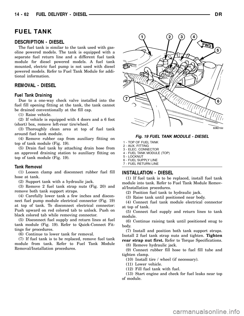
top of tank module (Fig. 19).
(5) Drain fuel tank by attaching drain hose from
an approved draining station to auxiliary fitting on
top of tank module (Fig. 19).
Tank Removal
(1) Loosen clamp and disconnect rubber fuel fill
hose at tank.
(2) Support tank with a hydraulic jack.
(3) Remove 2 fuel tank strap nuts (Fig. 20) and
remove both tank support straps.
(4) Carefully lower tank a few inches and discon-
nect fuel pump module electrical connector (Fig. 19)
at top of tank. To disconnect electrical connector:
Push upward on red colored tab to unlock. Push on
black colored tab while removing connector.
(5) Disconnect fuel supply and return lines at fuel
tank module (Fig. 19). Refer to Quick-Connect Fit-
tings for procedures.
(6) Continue to lower tank for removal.
(7) If fuel tank is to be replaced, remove fuel tank
module from tank. Refer to Fuel Tank Module
Removal/Installation procedures.INSTALLATION - DIESEL
(1) If fuel tank is to be replaced, install fuel tank
module into tank. Refer to Fuel Tank Module Remov-
al/Installation procedures.
(2) Position fuel tank to hydraulic jack.
(3) Raise tank until positioned near body.
(4) Connect fuel tank module electrical connector
at top of tank.
(5) Connect fuel supply and return lines to tank
module.
(6) Continue raising tank until positioned snug to
body.
(7) Install and position both tank support straps.
Install 2 fuel tank strap nuts and tighten.Tighten
rear strap nut first.Refer to Torque Specifications.
(8) Remove hydraulic jack.
(9) Connect rubber fill hose to fuel fill tube and
tighten clamp.
(10) Install tire / wheel (if necessary).
(11) Lower vehicle.
(12) Fill fuel tank with fuel.
(13) Start engine and check for fuel leaks near top
of module.
Fig. 19 FUEL TANK MODULE - DIESEL
1 - TOP OF FUEL TANK
2 - AUX. FITTING
3 - ELEC. CONNECTOR
4 - FUEL TANK MODULE (TOP)
5 - LOCKNUT
6 - FUEL SUPPLY LINE
7 - FUEL RETURN LINE
14 - 62 FUEL DELIVERY - DIESELDR
Page 1633 of 2627
INSTALLATION
CAUTION: Whenever the fuel tank module is ser-
viced, the rubber gasket must be replaced.
(1) Thoroughly clean locknut and locknut threads
at top of tank.(2) Using new gasket, carefully position fuel tank
module into opening in fuel tank.
(3) Position locknut over top of fuel tank module.
Install locknut finger tight.
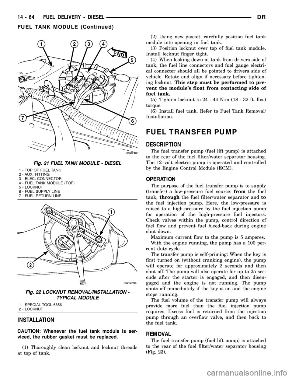
(4) When looking down at tank from drivers side of
tank, the fuel line connectors and fuel gauge electri-
cal connector should all be pointed to drivers side of
vehicle. Rotate and align if necessary before tighten-
ing locknut.This step must be performed to pre-
vent the module's float from contacting side of
fuel tank.
(5) Tighten locknut to 24 - 44 N´m (18 - 32 ft. lbs.)
torque.
(6) Install fuel tank. Refer to Fuel Tank Removal/
Installation.
FUEL TRANSFER PUMP
DESCRIPTION
The fuel transfer pump (fuel lift pump) is attached
to the rear of the fuel filter/water separator housing.
The 12±volt electric pump is operated and controlled
by the Engine Control Module (ECM).
OPERATION
The purpose of the fuel transfer pump is to supply
(transfer) a low-pressure fuel source:fromthe fuel
tank,throughthe fuel filter/water separator andto
the fuel injection pump. Here, the low-pressure is
raised to a high-pressure by the fuel injection pump
for operation of the high-pressure fuel injectors.
Check valves within the pump, control direction of
fuel flow and prevent fuel bleed-back during engine
shut down.
Maximum current flow to the pump is 5 amperes.
With the engine running, the pump has a 100 per-
cent duty-cycle.
The transfer pump is self-priming: When the key is
first turned on (without cranking engine), the pump
will operate for approximately 2 seconds and then
shut off. The pump will also operate for up to 25 sec-
onds after the starter is engaged, and then disen-
gaged and the engine is not running. The pump
shuts off immediately if the key is on and the engine
stops running.
The fuel volume of the transfer pump will always
provide more fuel than the fuel injection pump
requires. Excess fuel is returned from the injection
pump through an overflow valve, and then back to
the fuel tank.
REMOVAL
The fuel transfer pump (fuel lift pump) is attached
to the rear of the fuel filter/water separator housing
(Fig. 23).
Fig. 21 FUEL TANK MODULE - DIESEL
1 - TOP OF FUEL TANK
2 - AUX. FITTING
3 - ELEC. CONNECTOR
4 - FUEL TANK MODULE (TOP)
5 - LOCKNUT
6 - FUEL SUPPLY LINE
7 - FUEL RETURN LINE
Fig. 22 LOCKNUT REMOVAL/INSTALLATION -
TYPICAL MODULE
1 - SPECIAL TOOL 6856
2 - LOCKNUT
14 - 64 FUEL DELIVERY - DIESELDR
FUEL TANK MODULE (Continued)
Page 1634 of 2627
(1) Drain fuel from fuel filter housing. Refer to
Fuel Filter/Water Separator - Removal. See Draining.
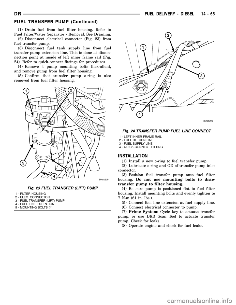
(2) Disconnect electrical connector (Fig. 23) from
fuel transfer pump.
(3) Disconnect fuel tank supply line from fuel
transfer pump extension line. This is done at discon-
nection point at inside of left inner frame rail (Fig.
24). Refer to quick-connect fittings for procedures.
(4) Remove 4 pump mounting bolts (hex-allen),
and remove pump from fuel filter housing.
(5) Confirm that transfer pump o-ring is also
removed from fuel filter housing.
INSTALLATION
(1) Install a new o-ring to fuel transfer pump.
(2) Lubricate o-ring and OD of transfer pump inlet
connector.
(3) Position fuel transfer pump onto fuel filter
housing.Do not use mounting bolts to draw
transfer pump to filter housing.
(4) Be sure pump is positioned flat to fuel filter
housing. Install mounting bolts and evenly tighten to
7 N´m (61 in. lbs.).
(5) Connect fuel line extension at fuel supply line.
(6) Connect electrical connector to pump.
(7)Prime System:Cycle key to actuate transfer
pump, or use DRB Scan Tool to actuate transfer
pump. Check for leaks.
(8) Operate engine and check for fuel leaks.
Fig. 23 FUEL TRANSFER (LIFT) PUMP
1 - FILTER HOUSING
2 - ELEC. CONNECTOR
3 - FUEL TRANSFER (LIFT) PUMP
4 - FUEL LINE EXTENTION
5 - MOUNTING BOLTS (4)
Fig. 24 TRANSFER PUMP FUEL LINE CONNECT
1 - LEFT INNER FRAME RAIL
2 - FUEL RETURN LINE
3 - FUEL SUPPLY LINE
4 - QUICK-CONNECT FITTING
DRFUEL DELIVERY - DIESEL 14 - 65
FUEL TRANSFER PUMP (Continued)
Page 1641 of 2627
is the primary engine speed indicator for the engine
after the engine is running.
REMOVAL
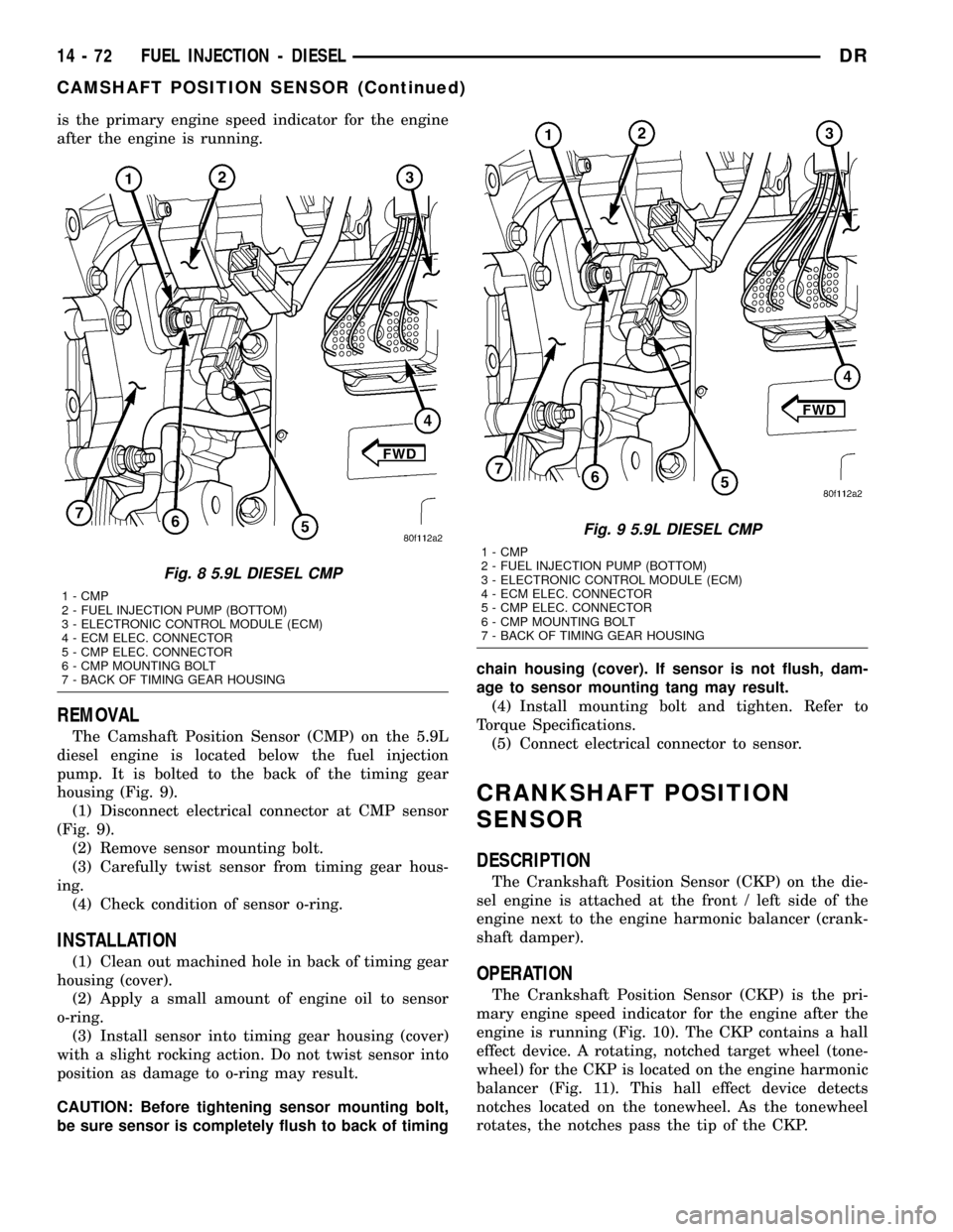
The Camshaft Position Sensor (CMP) on the 5.9L
diesel engine is located below the fuel injection
pump. It is bolted to the back of the timing gear
housing (Fig. 9).
(1) Disconnect electrical connector at CMP sensor
(Fig. 9).
(2) Remove sensor mounting bolt.
(3) Carefully twist sensor from timing gear hous-
ing.
(4) Check condition of sensor o-ring.
INSTALLATION
(1) Clean out machined hole in back of timing gear
housing (cover).
(2) Apply a small amount of engine oil to sensor
o-ring.
(3) Install sensor into timing gear housing (cover)
with a slight rocking action. Do not twist sensor into
position as damage to o-ring may result.
CAUTION: Before tightening sensor mounting bolt,
be sure sensor is completely flush to back of timingchain housing (cover). If sensor is not flush, dam-
age to sensor mounting tang may result.
(4) Install mounting bolt and tighten. Refer to
Torque Specifications.
(5) Connect electrical connector to sensor.
CRANKSHAFT POSITION
SENSOR
DESCRIPTION
The Crankshaft Position Sensor (CKP) on the die-
sel engine is attached at the front / left side of the
engine next to the engine harmonic balancer (crank-
shaft damper).
OPERATION
The Crankshaft Position Sensor (CKP) is the pri-
mary engine speed indicator for the engine after the
engine is running (Fig. 10). The CKP contains a hall
effect device. A rotating, notched target wheel (tone-
wheel) for the CKP is located on the engine harmonic
balancer (Fig. 11). This hall effect device detects
notches located on the tonewheel. As the tonewheel
rotates, the notches pass the tip of the CKP.
Fig. 8 5.9L DIESEL CMP
1 - CMP
2 - FUEL INJECTION PUMP (BOTTOM)
3 - ELECTRONIC CONTROL MODULE (ECM)
4 - ECM ELEC. CONNECTOR
5 - CMP ELEC. CONNECTOR
6 - CMP MOUNTING BOLT
7 - BACK OF TIMING GEAR HOUSING
Fig. 9 5.9L DIESEL CMP
1 - CMP
2 - FUEL INJECTION PUMP (BOTTOM)
3 - ELECTRONIC CONTROL MODULE (ECM)
4 - ECM ELEC. CONNECTOR
5 - CMP ELEC. CONNECTOR
6 - CMP MOUNTING BOLT
7 - BACK OF TIMING GEAR HOUSING
14 - 72 FUEL INJECTION - DIESELDR
CAMSHAFT POSITION SENSOR (Continued)
Page 1646 of 2627
INSTALLATION
(1)Inspect fuel injector:
(a) Look for burrs on injector inlet.
(b) Check nozzle holes for hole erosion or plug-
ging.
(c) Inspect end of nozzle for burrs or rough
machine marks.
(d) Look for cracks at nozzle end.
(e) If any of these conditions occur, replace injec-
tor.
(2) Thoroughly clean fuel injector cylinder head
bore. Blow out bore hole with compressed air.
(3) The bottom of fuel injector is sealed to cylinder
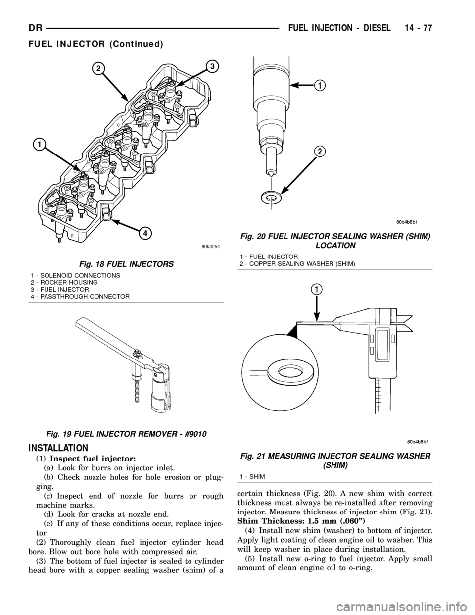
head bore with a copper sealing washer (shim) of acertain thickness (Fig. 20). A new shim with correct
thickness must always be re-installed after removing
injector. Measure thickness of injector shim (Fig. 21).
Shim Thickness: 1.5 mm (.060º)
(4) Install new shim (washer) to bottom of injector.
Apply light coating of clean engine oil to washer. This
will keep washer in place during installation.
(5) Install new o-ring to fuel injector. Apply small
amount of clean engine oil to o-ring.
Fig. 18 FUEL INJECTORS
1 - SOLENOID CONNECTIONS
2 - ROCKER HOUSING
3 - FUEL INJECTOR
4 - PASSTHROUGH CONNECTOR
Fig. 19 FUEL INJECTOR REMOVER - #9010
Fig. 20 FUEL INJECTOR SEALING WASHER (SHIM)
LOCATION
1 - FUEL INJECTOR
2 - COPPER SEALING WASHER (SHIM)
Fig. 21 MEASURING INJECTOR SEALING WASHER
(SHIM)
1 - SHIM
DRFUEL INJECTION - DIESEL 14 - 77
FUEL INJECTOR (Continued)
Page 1648 of 2627

(8) Connect battery cables to both batteries.
(9) Start engine and check for leaks.
INLET AIR TEMPERATURE
SENSOR/PRESSURE SENSOR
DESCRIPTION
The combination, dual function Inlet Air Tempera-
ture/Pressure Sensor is located on the air cleaner (fil-
ter) cover.
OPERATION
The Inlet Air Temperature/Pressure Sensor is a
combination dual-function sensor. The sensor element
extends into the intake air stream at the top of the
air filter housing. Ambient air temperature as well as
barometric pressure is monitored by this sensor. The
Engine Control Module (ECM) monitors signals from
this sensor.
REMOVAL
The Inlet Air Temperature/Pressure Sensor is
located on the air cleaner cover (Fig. 23).
(1) Disconnect electrical connector at sensor (Fig.
24).
(2) Remove two Torx-type mounting screws.
(3) Remove sensor from air cleaner cover.
(4) Check condition of sensor o-ring (Fig. 25).
INSTALLATION
(1) Check condition of sensor o-ring.
(2) Position sensor into top of air cleaner cover
with a slight twisting action.
(3) Install 2 mounting screws.
(4) Install electrical connector.
Fig. 22 FUEL INJECTOR RAIL
1 - FUEL RAIL MOUNTING BOLTS (3)
2 - INSULATED CLAMPS
3 - FUEL INJECTOR RAIL
Fig. 23 IAT/PRESSURE SENSOR LOCATION - 5.9L
DIESEL
1 - CLIPS
2 - FILTER COVER
3 - FILTER MINDERŸ
4 - INLET AIR TEMPERATURE/ PRESSURE SENSOR
5 - FILTER HOUSING
DRFUEL INJECTION - DIESEL 14 - 79
FUEL INJECTOR RAIL (Continued)
Page 1651 of 2627
INTAKE AIR HEATER RELAY
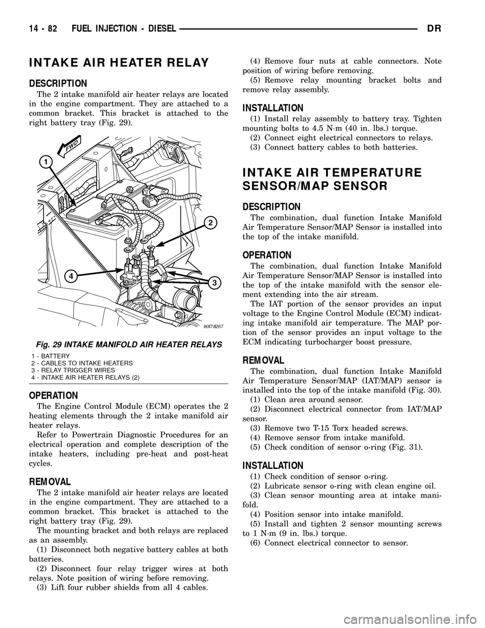
DESCRIPTION
The 2 intake manifold air heater relays are located
in the engine compartment. They are attached to a
common bracket. This bracket is attached to the
right battery tray (Fig. 29).
OPERATION
The Engine Control Module (ECM) operates the 2
heating elements through the 2 intake manifold air
heater relays.
Refer to Powertrain Diagnostic Procedures for an
electrical operation and complete description of the
intake heaters, including pre-heat and post-heat
cycles.
REMOVAL
The 2 intake manifold air heater relays are located
in the engine compartment. They are attached to a
common bracket. This bracket is attached to the
right battery tray (Fig. 29).
The mounting bracket and both relays are replaced
as an assembly.
(1) Disconnect both negative battery cables at both
batteries.
(2) Disconnect four relay trigger wires at both
relays. Note position of wiring before removing.
(3) Lift four rubber shields from all 4 cables.(4) Remove four nuts at cable connectors. Note
position of wiring before removing.
(5) Remove relay mounting bracket bolts and
remove relay assembly.
INSTALLATION
(1) Install relay assembly to battery tray. Tighten
mounting bolts to 4.5 N´m (40 in. lbs.) torque.
(2) Connect eight electrical connectors to relays.
(3) Connect battery cables to both batteries.
INTAKE AIR TEMPERATURE
SENSOR/MAP SENSOR
DESCRIPTION
The combination, dual function Intake Manifold
Air Temperature Sensor/MAP Sensor is installed into
the top of the intake manifold.
OPERATION
The combination, dual function Intake Manifold
Air Temperature Sensor/MAP Sensor is installed into
the top of the intake manifold with the sensor ele-
ment extending into the air stream.
The IAT portion of the sensor provides an input
voltage to the Engine Control Module (ECM) indicat-
ing intake manifold air temperature. The MAP por-
tion of the sensor provides an input voltage to the
ECM indicating turbocharger boost pressure.
REMOVAL
The combination, dual function Intake Manifold
Air Temperature Sensor/MAP (IAT/MAP) sensor is
installed into the top of the intake manifold (Fig. 30).
(1) Clean area around sensor.
(2) Disconnect electrical connector from IAT/MAP
sensor.
(3) Remove two T-15 Torx headed screws.
(4) Remove sensor from intake manifold.
(5) Check condition of sensor o-ring (Fig. 31).
INSTALLATION
(1) Check condition of sensor o-ring.
(2) Lubricate sensor o-ring with clean engine oil.
(3) Clean sensor mounting area at intake mani-
fold.
(4) Position sensor into intake manifold.
(5) Install and tighten 2 sensor mounting screws
to 1 N´m (9 in. lbs.) torque.
(6) Connect electrical connector to sensor.
Fig. 29 INTAKE MANIFOLD AIR HEATER RELAYS
1 - BATTERY
2 - CABLES TO INTAKE HEATERS
3 - RELAY TRIGGER WIRES
4 - INTAKE AIR HEATER RELAYS (2)
14 - 82 FUEL INJECTION - DIESELDR
Page 1653 of 2627
(6) Remove cable housing from dash panel and
pull cable into engine compartment.
(7) Remove cable housing at APPS bracket by
pressing on release tab with a small screwdriver.Toprevent cable housing breakage, press on tab
only enough to release cable from APPS
bracket.
INSTALLATION
Accelerator Pedal Position Sensor Mounted To Engine
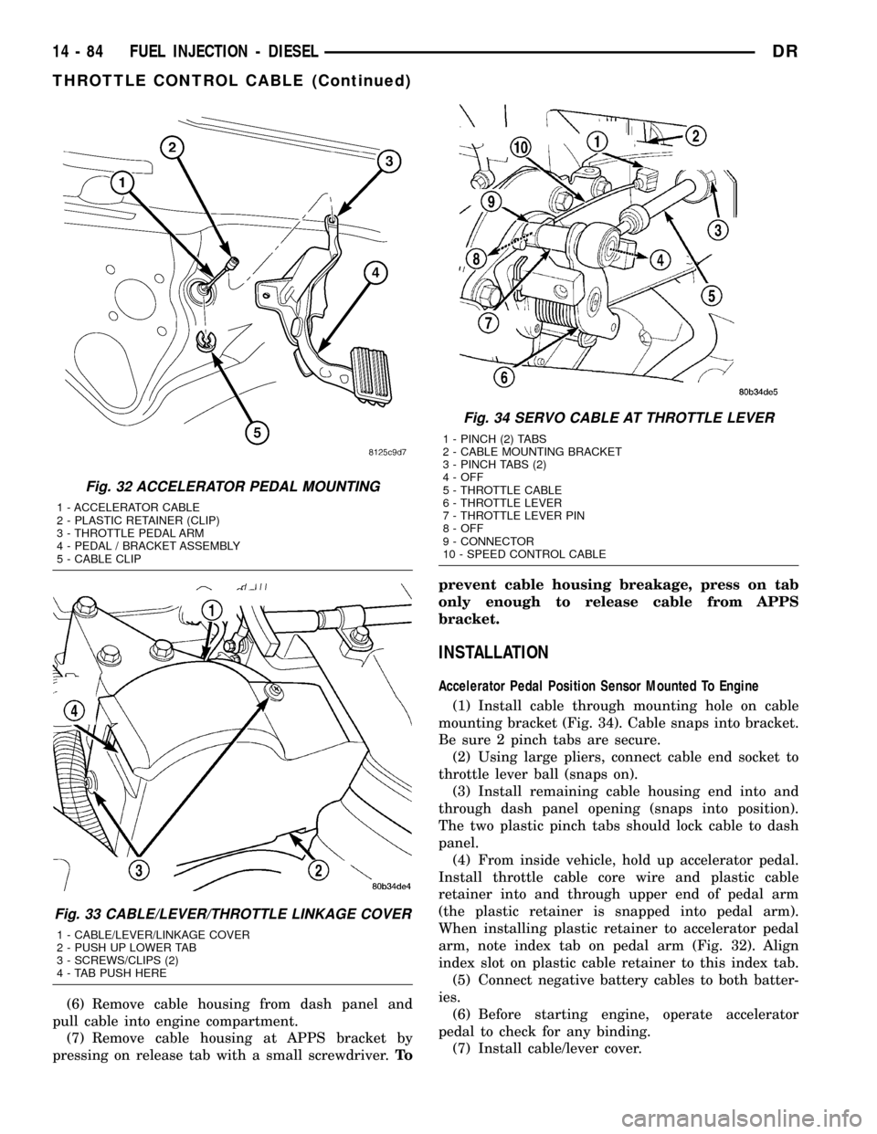
(1) Install cable through mounting hole on cable
mounting bracket (Fig. 34). Cable snaps into bracket.
Be sure 2 pinch tabs are secure.
(2) Using large pliers, connect cable end socket to
throttle lever ball (snaps on).
(3) Install remaining cable housing end into and
through dash panel opening (snaps into position).
The two plastic pinch tabs should lock cable to dash
panel.
(4) From inside vehicle, hold up accelerator pedal.
Install throttle cable core wire and plastic cable
retainer into and through upper end of pedal arm
(the plastic retainer is snapped into pedal arm).
When installing plastic retainer to accelerator pedal
arm, note index tab on pedal arm (Fig. 32). Align
index slot on plastic cable retainer to this index tab.
(5) Connect negative battery cables to both batter-
ies.
(6) Before starting engine, operate accelerator
pedal to check for any binding.
(7) Install cable/lever cover.
Fig. 32 ACCELERATOR PEDAL MOUNTING
1 - ACCELERATOR CABLE
2 - PLASTIC RETAINER (CLIP)
3 - THROTTLE PEDAL ARM
4 - PEDAL / BRACKET ASSEMBLY
5 - CABLE CLIP
Fig. 33 CABLE/LEVER/THROTTLE LINKAGE COVER
1 - CABLE/LEVER/LINKAGE COVER
2 - PUSH UP LOWER TAB
3 - SCREWS/CLIPS (2)
4 - TAB PUSH HERE
Fig. 34 SERVO CABLE AT THROTTLE LEVER
1 - PINCH (2) TABS
2 - CABLE MOUNTING BRACKET
3 - PINCH TABS (2)
4 - OFF
5 - THROTTLE CABLE
6 - THROTTLE LEVER
7 - THROTTLE LEVER PIN
8 - OFF
9 - CONNECTOR
10 - SPEED CONTROL CABLE
14 - 84 FUEL INJECTION - DIESELDR
THROTTLE CONTROL CABLE (Continued)