1998 DODGE RAM 1500 steering wheel adjustment
[x] Cancel search: steering wheel adjustmentPage 1675 of 2627
GEAR - LINK/COIL
TABLE OF CONTENTS
page page
GEAR - LINK/COIL
DESCRIPTION.........................20
OPERATION...........................20
REMOVAL.............................20
INSTALLATION.........................21
ADJUSTMENTS
ADJUSTMENT........................21
SPECIFICATIONS
POWER STEERING GEAR..............22
TORQUE CHART......................23
SPECIAL TOOLS
POWER STEERING GEAR..............23
PITMAN SHAFT SEAL
REMOVAL
REMOVAL - GAS ENGINE...............25REMOVAL - DIESEL...................25
INSTALLATION
INSTALLATION - GAS ENGINE...........26
INSTALLATION - DIESEL................26
STEERING GEAR INPUT SHAFT SEAL
REMOVAL.............................27
INSTALLATION.........................29
PITMAN SHAFT
REMOVAL
REMOVAL - GAS......................30
REMOVAL - DIESEL...................30
INSTALLATION
INSTALLATION - GAS..................31
INSTALLATION - DIESEL................31
GEAR - LINK/COIL
DESCRIPTION
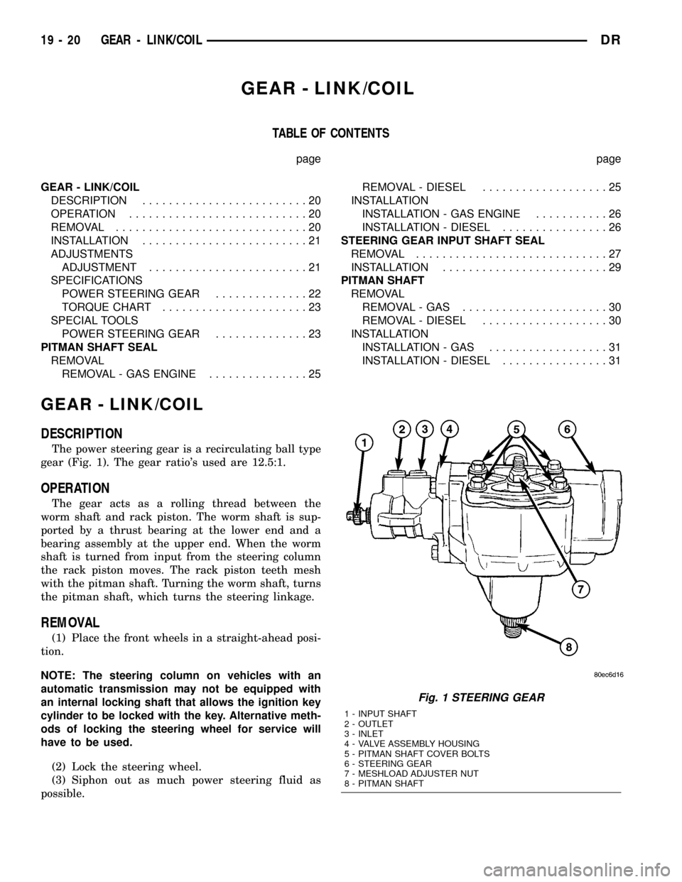
The power steering gear is a recirculating ball type
gear (Fig. 1). The gear ratio's used are 12.5:1.
OPERATION
The gear acts as a rolling thread between the
worm shaft and rack piston. The worm shaft is sup-
ported by a thrust bearing at the lower end and a
bearing assembly at the upper end. When the worm
shaft is turned from input from the steering column
the rack piston moves. The rack piston teeth mesh
with the pitman shaft. Turning the worm shaft, turns
the pitman shaft, which turns the steering linkage.
REMOVAL
(1) Place the front wheels in a straight-ahead posi-
tion.
NOTE: The steering column on vehicles with an
automatic transmission may not be equipped with
an internal locking shaft that allows the ignition key
cylinder to be locked with the key. Alternative meth-
ods of locking the steering wheel for service will
have to be used.
(2) Lock the steering wheel.
(3) Siphon out as much power steering fluid as
possible.
Fig. 1 STEERING GEAR
1 - INPUT SHAFT
2 - OUTLET
3 - INLET
4 - VALVE ASSEMBLY HOUSING
5 - PITMAN SHAFT COVER BOLTS
6 - STEERING GEAR
7 - MESHLOAD ADJUSTER NUT
8 - PITMAN SHAFT
19 - 20 GEAR - LINK/COILDR
Page 1676 of 2627
(4) Disconnect and cap the fluid hoses from steer-
ing gear (Refer to 19 - STEERING/PUMP/HOSES -
REMOVAL).
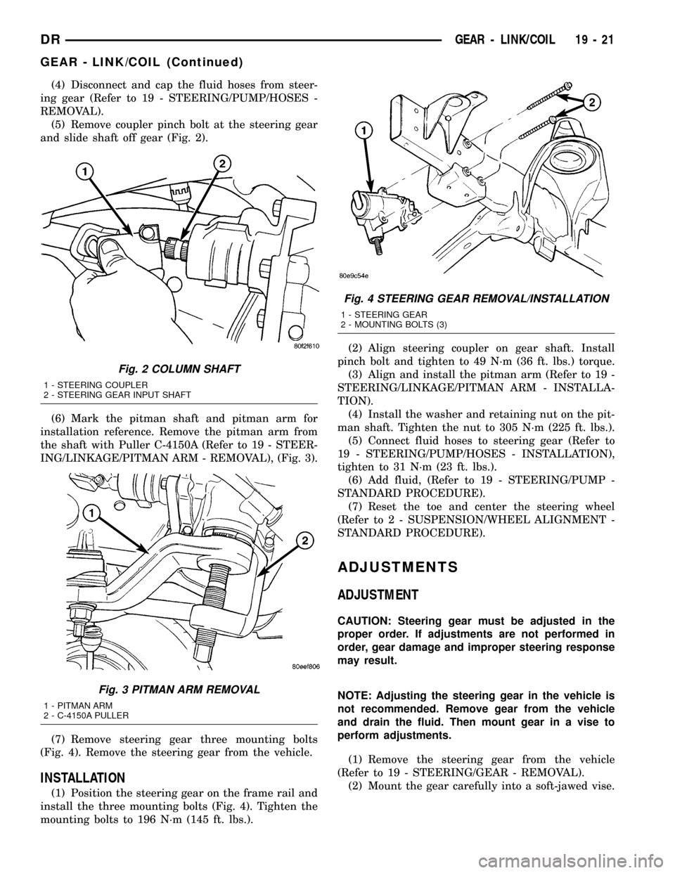
(5) Remove coupler pinch bolt at the steering gear
and slide shaft off gear (Fig. 2).
(6) Mark the pitman shaft and pitman arm for
installation reference. Remove the pitman arm from
the shaft with Puller C-4150A (Refer to 19 - STEER-
ING/LINKAGE/PITMAN ARM - REMOVAL), (Fig. 3).
(7) Remove steering gear three mounting bolts
(Fig. 4). Remove the steering gear from the vehicle.
INSTALLATION
(1) Position the steering gear on the frame rail and
install the three mounting bolts (Fig. 4). Tighten the
mounting bolts to 196 N´m (145 ft. lbs.).(2) Align steering coupler on gear shaft. Install
pinch bolt and tighten to 49 N´m (36 ft. lbs.) torque.
(3) Align and install the pitman arm (Refer to 19 -
STEERING/LINKAGE/PITMAN ARM - INSTALLA-
TION).
(4) Install the washer and retaining nut on the pit-
man shaft. Tighten the nut to 305 N´m (225 ft. lbs.).
(5) Connect fluid hoses to steering gear (Refer to
19 - STEERING/PUMP/HOSES - INSTALLATION),
tighten to 31 N´m (23 ft. lbs.).
(6) Add fluid, (Refer to 19 - STEERING/PUMP -
STANDARD PROCEDURE).
(7) Reset the toe and center the steering wheel
(Refer to 2 - SUSPENSION/WHEEL ALIGNMENT -
STANDARD PROCEDURE).
ADJUSTMENTS
ADJUSTMENT
CAUTION: Steering gear must be adjusted in the
proper order. If adjustments are not performed in
order, gear damage and improper steering response
may result.
NOTE: Adjusting the steering gear in the vehicle is
not recommended. Remove gear from the vehicle
and drain the fluid. Then mount gear in a vise to
perform adjustments.
(1) Remove the steering gear from the vehicle
(Refer to 19 - STEERING/GEAR - REMOVAL).
(2) Mount the gear carefully into a soft-jawed vise.
Fig. 2 COLUMN SHAFT
1 - STEERING COUPLER
2 - STEERING GEAR INPUT SHAFT
Fig. 3 PITMAN ARM REMOVAL
1 - PITMAN ARM
2 - C-4150A PULLER
Fig. 4 STEERING GEAR REMOVAL/INSTALLATION
1 - STEERING GEAR
2 - MOUNTING BOLTS (3)
DRGEAR - LINK/COIL 19 - 21
GEAR - LINK/COIL (Continued)
Page 1682 of 2627
(11) Install the pitman arm (Refer to 19 - STEER-
ING/LINKAGE/PITMAN ARM - INSTALLATION).
(12) Perform a wheel alignment (Refer to 2 - SUS-
PENSION/WHEEL ALIGNMENT - STANDARD
PROCEDURE).
STEERING GEAR INPUT
SHAFT SEAL
REMOVAL
(1) Remove the steering gear from the vehicle
(Refer to 19 - STEERING/GEAR - REMOVAL).
CAUTION: Do not overtighten the vise on the gear
case. This may affect the adjustment
(2) Mount the steering gear upside down over a
drain pan in a soft jawed vise.
(3) Place a drain pan under the gear and rotate
the input shaft back and forth several times lock-to-
lock to discharge the fluid from the steering gear
(4) Drain all the remaining fluid from the gear.
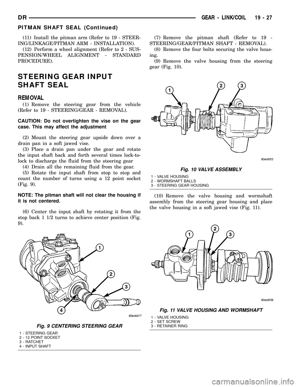
(5) Rotate the input shaft from stop to stop and
count the number of turns using a 12 point socket
(Fig. 9).
NOTE: The pitman shaft will not clear the housing if
it is not centered.
(6) Center the input shaft by rotating it from the
stop back 1 1/2 turns to achieve center position (Fig.
9).(7) Remove the pitman shaft (Refer to 19 -
STEERING/GEAR/PITMAN SHAFT - REMOVAL).
(8) Remove the four bolts securing the valve hous-
ing.
(9) Remove the valve housing from the steering
gear (Fig. 10).
(10) Remove the valve housing and wormshaft
assembly from the steering gear housing and place
the valve housing in a soft jawed vise (Fig. 11).
Fig. 9 CENTERING STEERING GEAR
1 - STEERING GEAR
2 - 12 POINT SOCKET
3 - RATCHET
4 - INPUT SHAFT
Fig. 10 VALVE ASSEMBLY
1 - VALVE HOUSING
2 - WORMSHAFT BALLS
3 - STEERING GEAR HOUSING
Fig. 11 VALVE HOUSING AND WORMSHAFT
1 - VALVE HOUSING
2 - SET SCREW
3 - RETAINER RING
DRGEAR - LINK/COIL 19 - 27
PITMAN SHAFT SEAL (Continued)
Page 1685 of 2627
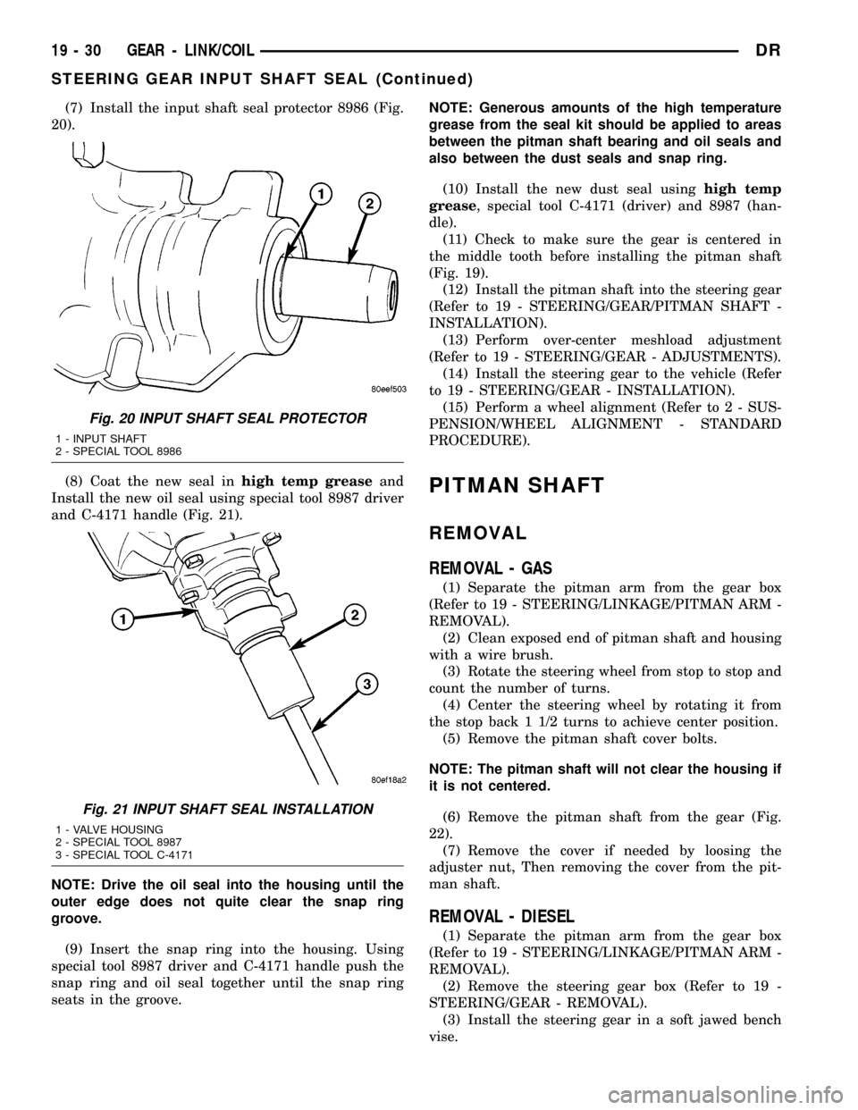
(7) Install the input shaft seal protector 8986 (Fig.
20).
(8) Coat the new seal inhigh temp greaseand
Install the new oil seal using special tool 8987 driver
and C-4171 handle (Fig. 21).
NOTE: Drive the oil seal into the housing until the
outer edge does not quite clear the snap ring
groove.
(9) Insert the snap ring into the housing. Using
special tool 8987 driver and C-4171 handle push the
snap ring and oil seal together until the snap ring
seats in the groove.NOTE: Generous amounts of the high temperature
grease from the seal kit should be applied to areas
between the pitman shaft bearing and oil seals and
also between the dust seals and snap ring.
(10) Install the new dust seal usinghigh temp
grease, special tool C-4171 (driver) and 8987 (han-
dle).
(11) Check to make sure the gear is centered in
the middle tooth before installing the pitman shaft
(Fig. 19).
(12) Install the pitman shaft into the steering gear
(Refer to 19 - STEERING/GEAR/PITMAN SHAFT -
INSTALLATION).
(13) Perform over-center meshload adjustment
(Refer to 19 - STEERING/GEAR - ADJUSTMENTS).
(14) Install the steering gear to the vehicle (Refer
to 19 - STEERING/GEAR - INSTALLATION).
(15) Perform a wheel alignment (Refer to 2 - SUS-
PENSION/WHEEL ALIGNMENT - STANDARD
PROCEDURE).
PITMAN SHAFT
REMOVAL
REMOVAL - GAS
(1) Separate the pitman arm from the gear box
(Refer to 19 - STEERING/LINKAGE/PITMAN ARM -
REMOVAL).
(2) Clean exposed end of pitman shaft and housing
with a wire brush.
(3) Rotate the steering wheel from stop to stop and
count the number of turns.
(4) Center the steering wheel by rotating it from
the stop back 1 1/2 turns to achieve center position.
(5) Remove the pitman shaft cover bolts.
NOTE: The pitman shaft will not clear the housing if
it is not centered.
(6) Remove the pitman shaft from the gear (Fig.
22).
(7) Remove the cover if needed by loosing the
adjuster nut, Then removing the cover from the pit-
man shaft.
REMOVAL - DIESEL
(1) Separate the pitman arm from the gear box
(Refer to 19 - STEERING/LINKAGE/PITMAN ARM -
REMOVAL).
(2) Remove the steering gear box (Refer to 19 -
STEERING/GEAR - REMOVAL).
(3) Install the steering gear in a soft jawed bench
vise.
Fig. 20 INPUT SHAFT SEAL PROTECTOR
1 - INPUT SHAFT
2 - SPECIAL TOOL 8986
Fig. 21 INPUT SHAFT SEAL INSTALLATION
1 - VALVE HOUSING
2 - SPECIAL TOOL 8987
3 - SPECIAL TOOL C-4171
19 - 30 GEAR - LINK/COILDR
STEERING GEAR INPUT SHAFT SEAL (Continued)
Page 1686 of 2627
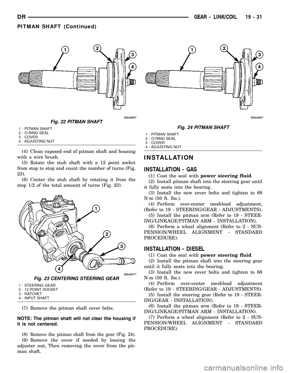
(4) Clean exposed end of pitman shaft and housing
with a wire brush.
(5) Rotate the stub shaft with a 12 point socket
from stop to stop and count the number of turns (Fig.
23).
(6) Center the stub shaft by rotating it from the
stop 1/2 of the total amount of turns (Fig. 23).
(7) Remove the pitman shaft cover bolts.
NOTE: The pitman shaft will not clear the housing if
it is not centered.
(8)
Remove the pitman shaft from the gear (Fig. 24).
(9) Remove the cover if needed by loosing the
adjuster nut, Then removing the cover from the pit-
man shaft.
INSTALLATION
INSTALLATION - GAS
(1) Coat the seal withpower steering fluid.
(2) Install pitman shaft into the steering gear until
it fully seats into the bearing.
(3) Install the new cover bolts and tighten to 68
N´m (50 ft. lbs.).
(4) Perform over-center meshload adjustment,
(Refer to 19 - STEERING/GEAR - ADJUSTMENTS).
(5) Install the pitman arm (Refer to 19 - STEER-
ING/LINKAGE/PITMAN ARM - INSTALLATION).
(6) Perform a wheel alignment (Refer to 2 - SUS-
PENSION/WHEEL ALIGNMENT - STANDARD
PROCEDURE).
INSTALLATION - DIESEL
(1) Coat the seal withpower steering fluid.
(2) Install the pitman shaft into the steering gear
until it fully seats into the bearing.
(3) Install the new cover bolts and tighten to 68
N´m (50 ft. lbs.).
(4) Perform over-center meshload adjustment
(Refer to 19 - STEERING/GEAR - ADJUSTMENTS).
(5) Install the steering gear (Refer to 19 - STEER-
ING/GEAR - INSTALLATION).
(6) Install the pitman arm (Refer to 19 - STEER-
ING/LINKAGE/PITMAN ARM - INSTALLATION).
(7) Perform a wheel alignment (Refer to 2 - SUS-
PENSION/WHEEL ALIGNMENT - STANDARD
PROCEDURE).
Fig. 22 PITMAN SHAFT
1 - PITMAN SHAFT
2 - O-RING SEAL
3 - COVER
4 - ADJUSTING NUT
Fig. 23 CENTERING STEERING GEAR
1 - STEERING GEAR
2 - 12 POINT SOCKET
3 - RATCHET
4 - INPUT SHAFT
Fig. 24 PITMAN SHAFT
1 - PITMAN SHAFT
2 - O-RING SEAL
3 - COVER
4 - ADJUSTING NUT
DRGEAR - LINK/COIL 19 - 31
PITMAN SHAFT (Continued)
Page 1691 of 2627
DAMPER
REMOVAL
(1) Remove the steering damper mounting nuts
and bolts.
(2) Slide the damper from the isolation bushing.
(3) Remove the damper.
INSTALLATION
(1) Install the steering damper on the axle and iso-
lation bushing. Tighten nut to 95 N´m (75 ft. lbs.).
(2) Install the steering damper on the tie rod.
Tighten nut to 81 N´m (60 ft. lbs.).
DRAG LINK
REMOVAL
(1) Remove the draglink nut from the pitman arm
side.
(2)
Remove the drag link nut from the knuckle side.
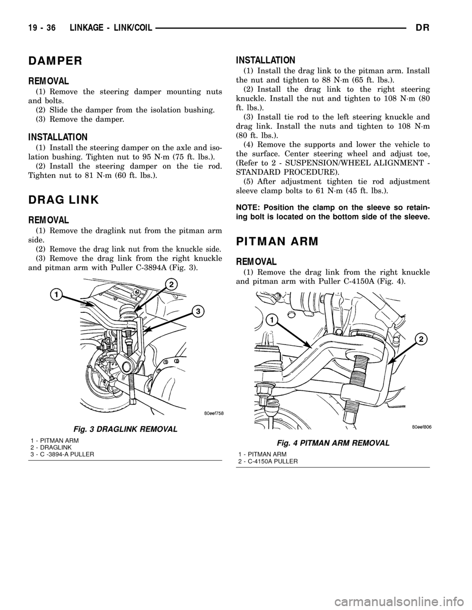
(3) Remove the drag link from the right knuckle
and pitman arm with Puller C-3894A (Fig. 3).
INSTALLATION
(1) Install the drag link to the pitman arm. Install
the nut and tighten to 88 N´m (65 ft. lbs.).
(2) Install the drag link to the right steering
knuckle. Install the nut and tighten to 108 N´m (80
ft. lbs.).
(3) Install tie rod to the left steering knuckle and
drag link. Install the nuts and tighten to 108 N´m
(80 ft. lbs.).
(4) Remove the supports and lower the vehicle to
the surface. Center steering wheel and adjust toe,
(Refer to 2 - SUSPENSION/WHEEL ALIGNMENT -
STANDARD PROCEDURE).
(5) After adjustment tighten tie rod adjustment
sleeve clamp bolts to 61 N´m (45 ft. lbs.).
NOTE: Position the clamp on the sleeve so retain-
ing bolt is located on the bottom side of the sleeve.
PITMAN ARM
REMOVAL
(1) Remove the drag link from the right knuckle
and pitman arm with Puller C-4150A (Fig. 4).
Fig. 3 DRAGLINK REMOVAL
1 - PITMAN ARM
2 - DRAGLINK
3 - C -3894-A PULLERFig. 4 PITMAN ARM REMOVAL
1 - PITMAN ARM
2 - C-4150A PULLER
19 - 36 LINKAGE - LINK/COILDR
Page 1692 of 2627
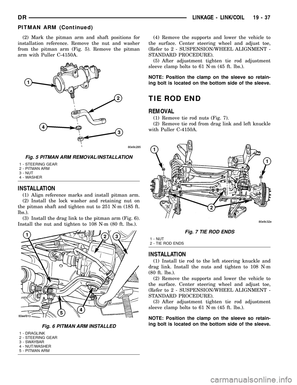
(2) Mark the pitman arm and shaft positions for
installation reference. Remove the nut and washer
from the pitman arm (Fig. 5). Remove the pitman
arm with Puller C-4150A.
INSTALLATION
(1) Align reference marks and install pitman arm.
(2) Install the lock washer and retaining nut on
the pitman shaft and tighten nut to 251 N´m (185 ft.
lbs.).
(3) Install the drag link to the pitman arm (Fig. 6).
Install the nut and tighten to 108 N´m (80 ft. lbs.).(4) Remove the supports and lower the vehicle to
the surface. Center steering wheel and adjust toe,
(Refer to 2 - SUSPENSION/WHEEL ALIGNMENT -
STANDARD PROCEDURE).
(5) After adjustment tighten tie rod adjustment
sleeve clamp bolts to 61 N´m (45 ft. lbs.).
NOTE: Position the clamp on the sleeve so retain-
ing bolt is located on the bottom side of the sleeve.
TIE ROD END
REMOVAL
(1) Remove tie rod nuts (Fig. 7).
(2) Remove tie rod from drag link and left knuckle
with Puller C-4150A.
INSTALLATION
(1) Install tie rod to the left steering knuckle and
drag link. Install the nuts and tighten to 108 N´m
(80 ft. lbs.).
(2) Remove the supports and lower the vehicle to
the surface. Center steering wheel and adjust toe,
(Refer to 2 - SUSPENSION/WHEEL ALIGNMENT -
STANDARD PROCEDURE).
(3) After adjustment tighten tie rod adjustment
sleeve clamp bolts to 61 N´m (45 ft. lbs.).
NOTE: Position the clamp on the sleeve so retain-
ing bolt is located on the bottom side of the sleeve.
Fig. 5 PITMAN ARM REMOVAL/INSTALLATION
1 - STEERING GEAR
2 - PITMAN ARM
3 - NUT
4 - WASHER
Fig. 6 PITMAN ARM INSTALLED
1 - DRAGLINK
2 - STEERING GEAR
3 - SWAYBAR
4 - NUT/WASHER
5 - PITMAN ARM
Fig. 7 TIE ROD ENDS
1 - NUT
2 - TIE ROD ENDS
DRLINKAGE - LINK/COIL 19 - 37
PITMAN ARM (Continued)
Page 2600 of 2627
FIRING ORDER / CABLE ROUTING, 5.7L
V-8 ENGINE..........................8I-4
FIRING ORDER, 3.7L V-6 - ENGINE........8I-4
FIRING ORDER, 4.7L V-8 - ENGINE........8I-4
FIRING ORDER, DIESEL - FUEL
INJECTOR..........................14-48
FITTING - DESCRIPTION, QUICK
CONNECT............................14-8
FITTING - STANDARD PROCEDURE,
CONNECTING ROD BEARING...........9-129
FITTING - STANDARD PROCEDURE,
CRANKSHAFT MAIN BEARING.....9-134,9-207
FITTING - STANDARD PROCEDURE,
PISTON...................9-139,9-211,9-51
FITTING - STANDARD PROCEDURE,
PISTON RING.........9-142,9-213,9-284,9-53
FITTING, STANDARD PROCEDURE -
CONNECTING ROD BEARING............9-49
FITTING, STANDARD PROCEDURE -
MAIN BEARING.......................9-44
FITTINGS - STANDARD PROCEDURE,
HANDLING TUBING...................24-45
FITTINGS - STANDARD PROCEDURE,
QUICK-CONNECT......................14-8
FLAG - INSTALLATION, SIDE VIEW
MIRROR...........................23-27
FLAG - REMOVAL, SIDE VIEW MIRROR . . . 23-27
FLARING - STANDARD PROCEDURE,
DOUBLE INVERTED....................5-10
FLARING - STANDARD PROCEDURE, ISO . . . 5-11
FLEX PLATE - INSTALLATION . . 9-138,9-210,9-48
FLEX PLATE - REMOVAL.......9-138,9-210,9-48
FLOOR - INSTALLATION, LOAD..........23-72
FLOOR - REMOVAL, LOAD.............23-71
FLOOR CONSOLE - INSTALLATION.......23-67
FLOOR CONSOLE - REMOVAL...........23-67
FLOOR DISTRIBUTION DUCT -
INSTALLATION.......................24-34
FLOOR DISTRIBUTION DUCT - REMOVAL . 24-33
FLOOR MATS - INSTALLATION, CARPETS . 23-65
FLOOR MATS - REMOVAL, CARPETS.....23-65
FLOOR SHIFT BOOT - INSTALLATION,
4WD ..............................23-62
FLOOR SHIFT BOOT - REMOVAL, 4WD....23-62
FLOOR SUPPORT CYLINDER -
INSTALLATION, LOAD.................23-72
FLOOR SUPPORT CYLINDER -
REMOVAL, LOAD.....................23-72
FLOW - 5.9L DIESEL - DESCRIPTION,
COOLING SYSTEM.....................7-3
FLOW - DIAGNOSIS AND TESTING,
RADIATOR COOLANT..............7-54,7-56
FLOW 3.7L/4.7L/5.7L ENGINE -
DESCRIPTION, COOLING SYSTEM.........7-1
FLOW AND PRESSURE - DIAGNOSIS
AND TESTING, POWER STEERING........19-4
FLUID - DESCRIPTION................19-43
FLUID - DESCRIPTION, AUTOMATIC
TRANSMISSION.......................0-4
FLUID - DESCRIPTION, POWER
STEERING............................0-3
FLUID - DIAGNOSIS AND TESTING,
CAUSES OF BURNT............21-201,21-366
FLUID - OPERATION, AUTOMATIC
TRANSMISSION.......................0-5
FLUID AND FILTER REPLACEMENT -
STANDARD PROCEDURE........21-203,21-367
FLUID CAPACITIES, SPECIFICATIONS.......0-5
FLUID CONTAMINATION - DIAGNOSIS
AND TESTING................21-202,21-366
FLUID CONTAMINATION - DIAGNOSIS
AND TESTING, BRAKE..................5-23
FLUID COOLER - INSTALLATION.........19-43
FLUID COOLER - REMOVAL............19-43
FLUID DRAIN AND REFILL - STANDARD
PROCEDURE.....21-441,21-476,21-507,21-537,
21-571
FLUID INDICATOR - DESCRIPTION,
WASHER
...........................8J-44
FLUID INDICATOR - OPERATION,
WASHER
...........................8J-44
FLUID LEAK - DIAGNOSIS AND TESTING,
CONVERTER HOUSING
.........21-144,21-318
FLUID LEVEL - DIAGNOSIS AND
TESTING, EFFECTS OF INCORRECT
.....21-201,
21-366
FLUID LEVEL - STANDARD PROCEDURE,
BRAKE
..............................5-23FLUID LEVEL CHECK - STANDARD
PROCEDURE.................21-202,21-366
FLUID LEVEL CHECKING - STANDARD
PROCEDURE, POWER STEERING........19-43
FLUID LEVEL SWITCH - DESCRIPTION,
WASHER............................8R-9
FLUID LEVEL SWITCH - INSTALLATION,
WASHER...........................8R-11
FLUID LEVEL SWITCH - OPERATION,
WASHER............................8R-9
FLUID LEVEL SWITCH - REMOVAL,
WASHER...........................8R-10
FLUID RESERVOIR - INSTALLATION.......5-24
FLUID RESERVOIR - REMOVAL..........5-23
FLUID, SPECIFICATIONS - BRAKE.........5-23
FLUSH - SPECIFICATIONS, GAP.........23-95
FLUSHING - STANDARD PROCEDURE,
COOLING SYSTEM CLEANING/
REVERSE............................7-17
FLUSHING POWER STEERING SYSTEM -
STANDARD PROCEDURE...............19-40
FLYWHEEL - ASSEMBLY................6-11
FLYWHEEL - DIAGNOSIS AND TESTING....6-10
FLYWHEEL - DISASSEMBLY.............6-11
FLYWHEEL - INSTALLATION.............6-11
FLYWHEEL - REMOVAL.................6-11
FOG LAMP - INSTALLATION............8L-12
FOG LAMP - REMOVAL................8L-12
FOG LAMP RELAY - DESCRIPTION.......8L-12
FOG LAMP RELAY - INSTALLATION........8L-13
FOG LAMP RELAY - OPERATION.........8L-13
FOG LAMP RELAY - REMOVAL..........8L-13
FOOTMANS LOOP BRACKETS -
INSTALLATION, SEAT BACK REAR.......23-85
FOOTMANS LOOP BRACKETS -
REMOVAL, SEAT BACK REAR...........23-85
FORM-IN-PLACE GASKETS AND
SEALERS - STANDARD PROCEDURE . . 9-239,9-9,
9-94
FRAME - INSTALLATION, GRILLE........23-40
FRAME - REAR - INSTALLATION, SEAT
CUSHION...........................23-85
FRAME - REAR - REMOVAL, SEAT
CUSHION...........................23-85
FRAME - REMOVAL, GRILLE............23-40
FRAME DIMENSIONS - SPECIFICATIONS . . 13-16
FRAME H-SECTION REPLACEMENT -
STANDARD PROCEDURE, REAR.........13-13
FRAME RAIL TIP REPLACEMENT -
STANDARD PROCEDURE, LIGHT DUTY
FRONT..............................13-4
FREE MODULE - INSTALLATION, HANDS . . . 8T-2
FREE MODULE - REMOVAL, HANDS.......8T-2
FRONT - INSTALLATION....5-16,5-21,5-22,5-34
FRONT - INSTALLATION...............22-14
FRONT - INSTALLATION, CRANKSHAFT
OIL SEAL.............9-136,9-208,9-275,9-46
FRONT - INSTALLATION, PROPELLER
SHAFT - HD...........................3-7
FRONT - INSTALLATION, PROPELLER
SHAFT- LD............................3-7
FRONT - INSTALLATION, SEAT..........23-81
FRONT - INSTALLATION, SEAT BACK
CUSHION / COVER...................23-82
FRONT - INSTALLATION, SEAT CUSHION
/ COVER............................23-83
FRONT - REMOVAL........5-13,5-17,5-21,5-33
FRONT - REMOVAL, CRANKSHAFT OIL
SEAL................9-135,9-208,9-275,9-46
FRONT - REMOVAL, PROPELLER SHAFT
- HD ................................3-7
FRONT - REMOVAL, PROPELLER SHAFT-
LD ..................................3-6
FRONT - REMOVAL, SEAT..............23-81
FRONT - REMOVAL, SEAT BACK
CUSHION / COVER...................23-82
FRONT - REMOVAL, SEAT CUSHION /
COVER.............................23-83
FRONT AIR DAM - INSTALLATION........13-2
FRONT AIR DAM - REMOVAL............13-2
FRONT AXLE - 9 1/4 AA -
ADJUSTMENTS
.......................3-59
FRONT AXLE - 9 1/4 AA - DIAGNOSIS
AND TESTING
........................3-54
FRONT AXLE - 9 1/4 AA - INSTALLATION
. . . 3-58
FRONT AXLE - 9 1/4 AA - REMOVAL
......3-57
FRONT AXLE - 9 1/4 AA - SPECIAL
TOOLS
..............................3-64FRONT AXLE - 9 1/4 AA -
SPECIFICATIONS......................3-63
FRONT AXLE - C205F - ADJUSTMENTS....3-32
FRONT AXLE - C205F - DIAGNOSIS AND
TESTING............................3-27
FRONT AXLE - C205F - INSTALLATION.....3-31
FRONT AXLE - C205F - REMOVAL........3-31
FRONT AXLE - C205F - SPECIAL TOOLS . . . 3-40
FRONT AXLE - C205F - SPECIFICATIONS . . . 3-39
FRONT BEARING - INSTALLATION,
OUTPUT SHAFT.....................21-216
FRONT BEARING - REMOVAL, OUTPUT
SHAFT............................21-216
FRONT BRAKE HOSE - INSTALLATION.....5-13
FRONT BUMPER - INSTALLATION.........13-2
FRONT BUMPER - REMOVAL............13-2
FRONT CENTER SEAT BELT -
INSTALLATION......................8O-31
FRONT CENTER SEAT BELT - REMOVAL . . 8O-30
FRONT CENTER SEAT BELT &
RETRACTOR - INSTALLATION...........8O-29
FRONT CENTER SEAT BELT &
RETRACTOR - REMOVAL..............8O-29
FRONT CLUTCH - ASSEMBLY..........21-207
FRONT CLUTCH - DESCRIPTION........21-205
FRONT CLUTCH - DISASSEMBLY.......21-205
FRONT CLUTCH - INSPECTION.........21-206
FRONT CLUTCH - OPERATION.........21-205
FRONT CONTROL MODULE -
DESCRIPTION.....................8W-97-5
FRONT CONTROL MODULE -
DESCRIPTION........................8E-5
FRONT CONTROL MODULE - DIAGNOSIS
AND TESTING.....................8W-97-5
FRONT CONTROL MODULE - DIAGNOSIS
AND TESTING........................8E-5
FRONT CONTROL MODULE -
INSTALLATION....................8W-97-6
FRONT CONTROL MODULE -
INSTALLATION........................8E-5
FRONT CONTROL MODULE - OPERATION . 8W-97-5
FRONT CONTROL MODULE - OPERATION . . 8E-5
FRONT CONTROL MODULE - REMOVAL . 8W-97-6
FRONT CONTROL MODULE - REMOVAL....8E-5
FRONT CROSSMEMBER - INSTALLATION . . 13-22
FRONT CROSSMEMBER - REMOVAL.....13-22
FRONT DOOR GLASS RUN
WEATHERSTRIP - INSTALLATION........23-92
FRONT DOOR GLASS RUN
WEATHERSTRIP - REMOVAL............23-92
FRONT DOOR INNER BELT MOLDING -
INSTALLATION.......................23-93
FRONT DOOR INNER BELT MOLDING -
REMOVAL..........................23-93
FRONT DOOR OUTER BELT MOLDING -
INSTALLATION.......................23-93
FRONT DOOR OUTER BELT MOLDING -
REMOVAL..........................23-92
FRONT FASCIA - INSTALLATION..........13-3
FRONT FASCIA - REMOVAL..............13-2
FRONT FENDER - INSTALLATION........23-39
FRONT FENDER - REMOVAL............23-39
FRONT FRAME RAIL TIP REPLACEMENT
- STANDARD PROCEDURE, LIGHT
DUTY...............................13-4
FRONT HOSE - REMOVAL...............5-12
FRONT MOUNT - INSTALLATION . . . 9-147,9-218,
9-287,9-59
FRONT MOUNT - REMOVAL . . 9-146,9-217,9-286,
9-58
FRONT OUTBOARD SEAT BELT BUCKLE -
INSTALLATION......................8O-38
FRONT OUTBOARD SEAT BELT BUCKLE -
REMOVAL..........................8O-37
FRONT OUTPUT SHAFT SEAL -
INSTALLATION . . . 21-442,21-477,21-508,21-538,
21-572
FRONT OUTPUT SHAFT SEAL -
REMOVAL . 21-441,21-477,21-507,21-537,21-572
FRONT PARKING BRAKE CABLE -
INSTALLATION........................5-38
FRONT PARKING BRAKE CABLE -
REMOVAL
...........................5-36
FRONT SEAL - INSTALLATION, OIL
PUMP
............................21-391
FRONT SEAL - REMOVAL, OIL PUMP
....21-391
FRONT SERVO - ASSEMBLY
...........21-209
FRONT SERVO - CLEANING
...........21-209
DRINDEX 13
Description Group-Page Description Group-Page Description Group-Page