1998 DODGE RAM 1500 hood open
[x] Cancel search: hood openPage 2213 of 2627

SELECTOR SWITCH
DESCRIPTION
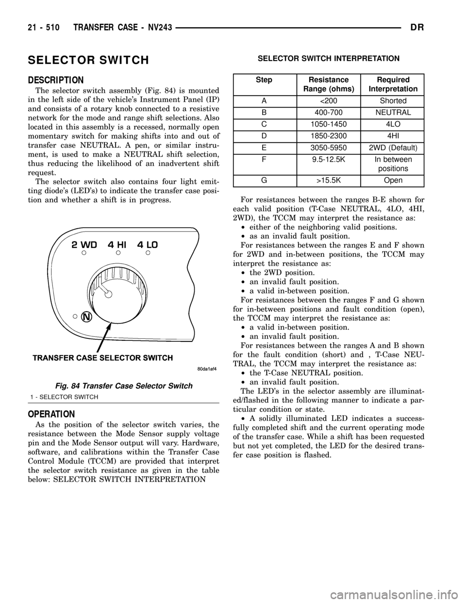
The selector switch assembly (Fig. 84) is mounted
in the left side of the vehicle's Instrument Panel (IP)
and consists of a rotary knob connected to a resistive
network for the mode and range shift selections. Also
located in this assembly is a recessed, normally open
momentary switch for making shifts into and out of
transfer case NEUTRAL. A pen, or similar instru-
ment, is used to make a NEUTRAL shift selection,
thus reducing the likelihood of an inadvertent shift
request.
The selector switch also contains four light emit-
ting diode's (LED's) to indicate the transfer case posi-
tion and whether a shift is in progress.
OPERATION
As the position of the selector switch varies, the
resistance between the Mode Sensor supply voltage
pin and the Mode Sensor output will vary. Hardware,
software, and calibrations within the Transfer Case
Control Module (TCCM) are provided that interpret
the selector switch resistance as given in the table
below: SELECTOR SWITCH INTERPRETATIONSELECTOR SWITCH INTERPRETATION
Step Resistance
Range (ohms)Required
Interpretation
A <200 Shorted
B 400-700 NEUTRAL
C 1050-1450 4LO
D 1850-2300 4HI
E 3050-5950 2WD (Default)
F 9.5-12.5K In between
positions
G >15.5K Open
For resistances between the ranges B-E shown for
each valid position (T-Case NEUTRAL, 4LO, 4HI,
2WD), the TCCM may interpret the resistance as:
²either of the neighboring valid positions.
²as an invalid fault position.
For resistances between the ranges E and F shown
for 2WD and in-between positions, the TCCM may
interpret the resistance as:
²the 2WD position.
²an invalid fault position.
²a valid in-between position.
For resistances between the ranges F and G shown
for in-between positions and fault condition (open),
the TCCM may interpret the resistance as:
²a valid in-between position.
²an invalid fault position.
For resistances between the ranges A and B shown
for the fault condition (short) and , T-Case NEU-
TRAL, the TCCM may interpret the resistance as:
²the T-Case NEUTRAL position.
²an invalid fault position.
The LED's in the selector assembly are illuminat-
ed/flashed in the following manner to indicate a par-
ticular condition or state.
²A solidly illuminated LED indicates a success-
fully completed shift and the current operating mode
of the transfer case. While a shift has been requested
but not yet completed, the LED for the desired trans-
fer case position is flashed.
Fig. 84 Transfer Case Selector Switch
1 - SELECTOR SWITCH
21 - 510 TRANSFER CASE - NV243DR
Page 2242 of 2627

OPERATION
During normal vehicle operation, the Transfer Case
Control Module (TCCM) monitors the mode sensor
outputs at least every 250 (+/-50) milliseconds when
the shift motor is stationary and 400 microseconds
when the shift motor is active. A mode sensor signal
between 3.8 Volts and 0.8 Volts is considered to be
undefined.
Refer to SECTOR ANGLES vs. TRANSFER CASE
POSITION for the relative angles of the transfer case
shift sector versus the interpreted transfer case gear
operating mode. Refer to MODE SENSOR CHAN-
NEL STATES for the sensor codes returned to the
TCCM for each transfer case mode sensor position.The various between gears positions can also be
referred as the transfer case's coarse position. These
coarse positions come into play during shift attempts.
SECTOR ANGLES VS. TRANSFER CASE POSITION
Shaft Angle (Degrees) Transfer Case Position
+40 4LO
+20 N
0 2WD/AWD
-20 4HI
MODE SENSOR CHANNEL STATES
Transfer Case
Angle (degrees)Sensor Channel A Sensor Channel B Sensor Channel C Sensor Channel D
Between Gears H H L H
+40 (4LO) H H L L
Between Gears H H L H
Between Gears H L L H
+20 (NEUTRAL) H L L L
Between Gears H L L H
Between Gears H L H H
0 (2WD/AWD) H L H L
Between Gears H L H H
Between Gears L L H H
-20 (4HI) L L H L
Between Gears L L H H
Between Gears L H H H
SELECTOR SWITCH
DESCRIPTION
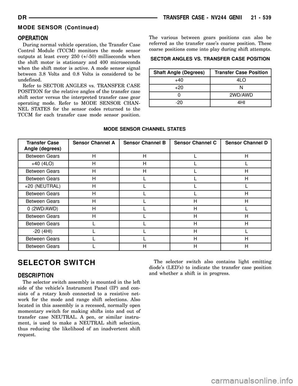
The selector switch assembly is mounted in the left
side of the vehicle's Instrument Panel (IP) and con-
sists of a rotary knob connected to a resistive net-
work for the mode and range shift selections. Also
located in this assembly is a recessed, normally open
momentary switch for making shifts into and out of
transfer case NEUTRAL. A pen, or similar instru-
ment, is used to make a NEUTRAL shift selection,
thus reducing the likelihood of an inadvertent shift
request.The selector switch also contains light emitting
diode's (LED's) to indicate the transfer case position
and whether a shift is in progress.
DRTRANSFER CASE - NV244 GENII 21 - 539
MODE SENSOR (Continued)
Page 2277 of 2627

SELECTOR SWITCH
DESCRIPTION
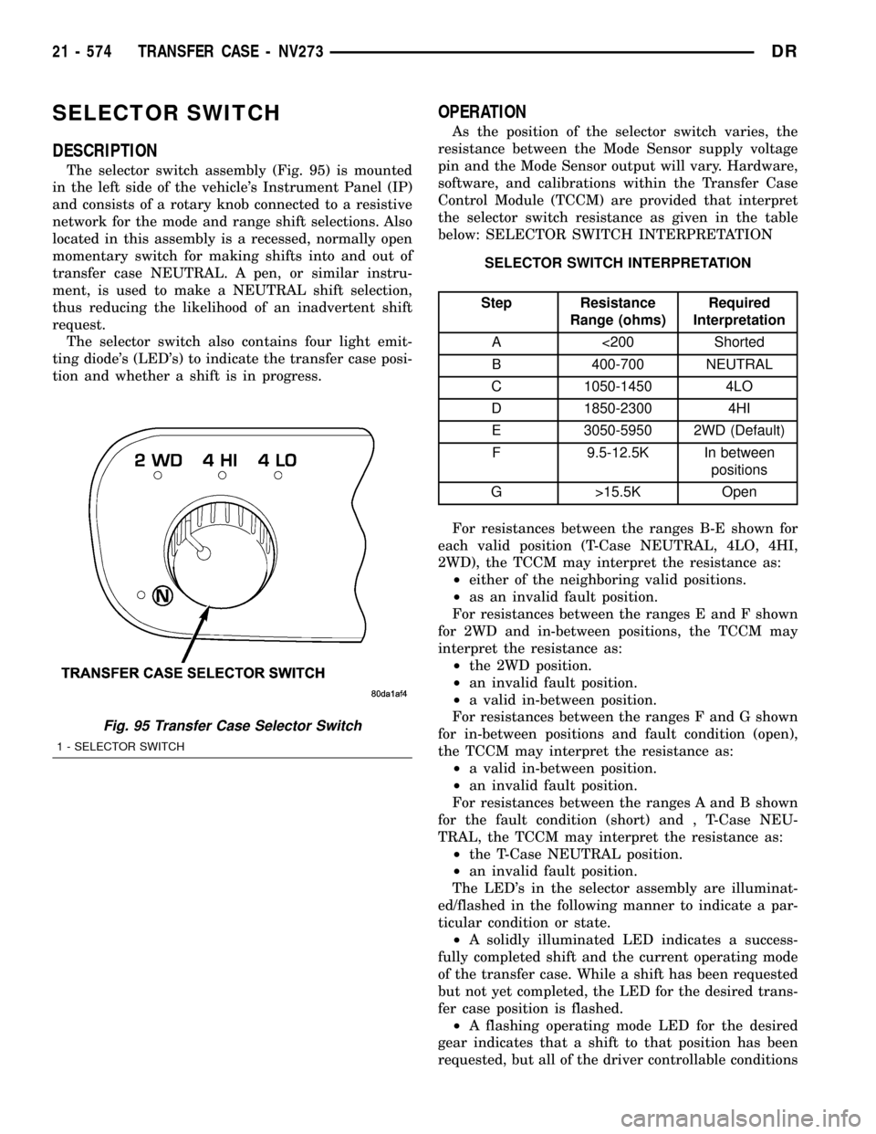
The selector switch assembly (Fig. 95) is mounted
in the left side of the vehicle's Instrument Panel (IP)
and consists of a rotary knob connected to a resistive
network for the mode and range shift selections. Also
located in this assembly is a recessed, normally open
momentary switch for making shifts into and out of
transfer case NEUTRAL. A pen, or similar instru-
ment, is used to make a NEUTRAL shift selection,
thus reducing the likelihood of an inadvertent shift
request.
The selector switch also contains four light emit-
ting diode's (LED's) to indicate the transfer case posi-
tion and whether a shift is in progress.
OPERATION
As the position of the selector switch varies, the
resistance between the Mode Sensor supply voltage
pin and the Mode Sensor output will vary. Hardware,
software, and calibrations within the Transfer Case
Control Module (TCCM) are provided that interpret
the selector switch resistance as given in the table
below: SELECTOR SWITCH INTERPRETATION
SELECTOR SWITCH INTERPRETATION
Step Resistance
Range (ohms)Required
Interpretation
A <200 Shorted
B 400-700 NEUTRAL
C 1050-1450 4LO
D 1850-2300 4HI
E 3050-5950 2WD (Default)
F 9.5-12.5K In between
positions
G >15.5K Open
For resistances between the ranges B-E shown for
each valid position (T-Case NEUTRAL, 4LO, 4HI,
2WD), the TCCM may interpret the resistance as:
²either of the neighboring valid positions.
²as an invalid fault position.
For resistances between the ranges E and F shown
for 2WD and in-between positions, the TCCM may
interpret the resistance as:
²the 2WD position.
²an invalid fault position.
²a valid in-between position.
For resistances between the ranges F and G shown
for in-between positions and fault condition (open),
the TCCM may interpret the resistance as:
²a valid in-between position.
²an invalid fault position.
For resistances between the ranges A and B shown
for the fault condition (short) and , T-Case NEU-
TRAL, the TCCM may interpret the resistance as:
²the T-Case NEUTRAL position.
²an invalid fault position.
The LED's in the selector assembly are illuminat-
ed/flashed in the following manner to indicate a par-
ticular condition or state.
²A solidly illuminated LED indicates a success-
fully completed shift and the current operating mode
of the transfer case. While a shift has been requested
but not yet completed, the LED for the desired trans-
fer case position is flashed.
²A flashing operating mode LED for the desired
gear indicates that a shift to that position has been
requested, but all of the driver controllable conditions
Fig. 95 Transfer Case Selector Switch
1 - SELECTOR SWITCH
21 - 574 TRANSFER CASE - NV273DR
Page 2334 of 2627

FRONT FENDER
REMOVAL
(1) Remove the antenna, if equipped. (Refer to 8 -
ELECTRICAL/AUDIO/ANTENNA BODY & CABLE -
REMOVAL)
(2) Remove the battery tray, if required. (Refer to 8
- ELECTRICAL/BATTERY SYSTEM/TRAY -
REMOVAL)
(3) Remove the cowl grille. (Refer to 23 - BODY/
EXTERIOR/COWL GRILLE - REMOVAL)
(4) Remove the headlamp unit. (Refer to 8 - ELEC-
TRICAL/LAMPS/LIGHTING - EXTERIOR/HEAD-
LAMP UNIT - REMOVAL)
(5) Remove the wheelhouse splash shield. (Refer to
23 - BODY/EXTERIOR/FRONT WHEELHOUSE
SPLASH SHIELD - REMOVAL)
(6) Remove the inside and lower bolts. (Fig. 6)
(7) Remove the two bolts below the headlamp.
(8) Remove the hinge support bolt at the cowl.
(9) Remove the three bolts along the fender rail.
INSTALLATION
(1) Install the three bolts along the upper fender
rail and tighten to 9 N´m (80 in. lbs.).
(2) Install the upper hinge support bolt at the cowl
and tighten to 17 N´m (13 ft. lbs.).
(3) Install the two bolts below the headlamp and
tighten to 9 N´m (80 in. lbs.).(4) Install the inside and lower bolts and tighten
to 17 N´m (13 ft. lbs.).
(5) Check the fender positioning and adjust as
required by adding shims. (Refer to 23 - BODY/
BODY STRUCTURE/GAP AND FLUSH - SPECIFI-
CATIONS)
(6) Install the wheelhouse splash shield. (Refer to
23 - BODY/EXTERIOR/FRONT WHEELHOUSE
SPLASH SHIELD - INSTALLATION)
(7) Install the headlamp unit. (Refer to 8 - ELEC-
TRICAL/LAMPS/LIGHTING - EXTERIOR/HEAD-
LAMP UNIT - INSTALLATION)
(8) Install the cowl grille. (Refer to 23 - BODY/EX-
TERIOR/COWL GRILLE - INSTALLATION)
(9) Install the battery tray, if required. (Refer to 8
- ELECTRICAL/BATTERY SYSTEM/TRAY -
INSTALLATION)
(10) Install the antenna, if required. (Refer to 8 -
ELECTRICAL/AUDIO/ANTENNA BODY & CABLE -
INSTALLATION)
FUEL FILL DOOR
REMOVAL
(1) Open fill door and remove the bolts. (Fig. 7)
(2) Remove the door.
INSTALLATION
(1) Install the fuel fill door.
(2) Install the bolts and tighten to 9 N´m (80 in.
lbs.).
Fig. 6 FRONT FENDER
1 - HOOD HINGE SUPPORT BOLT (1)
2 - HOOD HINGE
3 - INNER BOLT (1)
4 - FRONT BOLTS (2)
5 - LOWER BOLT INSERT
6 - FENDER
7 - UPPER BOLTS (3)
Fig. 7 FUEL FILL DOOR
1 - FUEL FILL DOOR
2 - BOLTS (2)
DREXTERIOR 23 - 39
Page 2335 of 2627

GRILLE
REMOVAL
(1) Open the hood.
(2) Remove the six lower screws. (Fig. 8)
(3) Remove the six upper nuts and separate the
grille from the grille frame.
INSTALLATION
(1) Position the grille onto the grille frame.
(2) Install the six upper nuts.
(3) Install the six lower screws.
GRILLE FRAME
REMOVAL
(1) Remove the grille. (Refer to 23 - BODY/EXTE-
RIOR/GRILLE - REMOVAL)
(2) Remove the screws and remove the grille
frame. (Fig. 9)
INSTALLATION
(1) Install the grille frame and install the six
screws.
(2) Install the grille. (Refer to 23 - BODY/EXTERI-
OR/GRILLE - INSTALLATION)
Fig. 8 GRILLE
1 - NUTS (6)
2 - HOOD
3 - GRILLE
4 - GRILLE FRAME
5 - SCREWS (6)
Fig. 9 GRILLE FRAME
1 - HOOD
2 - GRILLE FRAME
3 - SCREWS (6)
23 - 40 EXTERIORDR
Page 2341 of 2627

HOOD
TABLE OF CONTENTS
page page
HINGE
REMOVAL.............................46
INSTALLATION.........................46
HOOD
REMOVAL.............................46
INSTALLATION.........................47
LATCH
REMOVAL.............................47
INSTALLATION.........................47LATCH RELEASE CABLE/HANDLE ASSEMBLY
REMOVAL.............................47
INSTALLATION.........................47
LATCH STRIKER / SECONDARY CATCH
REMOVAL.............................47
INSTALLATION.........................48
SUPPORT CYLINDER
REMOVAL.............................48
INSTALLATION.........................48
HINGE
REMOVAL
NOTE: It is not necessary to remove the hood to
replace one or both hinges. The hinges can be
replaced one at a time.
(1) Remove the cowl grille. (Refer to 23 - BODY/
EXTERIOR/COWL GRILLE - REMOVAL)
(2) Using a grease pencil or equivalent, mark the
position of the hinge on the hood.
(3) Remove the fender support bolt. (Fig. 1)
(4) Remove the support cylinder. (Refer to 23 -
BODY/HOOD/SUPPORT CYLINDER - REMOVAL)
(5) Remove the hood nuts.
(6) Remove the wheelhouse splash shield. (Refer to
23 - BODY/EXTERIOR/FRONT WHEELHOUSE
SPLASH SHIELD - REMOVAL)
(7) From inside the fender, remove the two hinge
bolts. (Fig. 2)
(8) Slide the hinge forward and remove from the
fender rail.
INSTALLATION
(1) Install the hinge and slide back into position
on the fender rail.
(2) From inside the fender, install the two hinge
bolts and tighten to 20 N´m (15 ft. lbs.).
(3) Install the hood nuts and line up the marks
made previously.
(4) Tighten the nuts to 23 N´m (17 ft. lbs.).
(5) Install the support cylinder. (Refer to 23 -
BODY/HOOD/SUPPORT CYLINDER - INSTALLA-
TION)
(6) Install the fender support bolt and tighten to
11 N´m (8 ft. lbs.).(7) Check hood fit and adjust if required. (Refer to
23 - BODY/BODY STRUCTURE/GAP AND FLUSH -
SPECIFICATIONS)
(8) Install the cowl grille. (Refer to 23 - BODY/EX-
TERIOR/COWL GRILLE - INSTALLATION)
(9) Install the wheelhouse splash shield. (Refer to
23 - BODY/EXTERIOR/FRONT WHEELHOUSE
SPLASH SHIELD - INSTALLATION)
HOOD
REMOVAL
(1) Open the hood.
(2) Using a grease pencil or equivalent, mark the
position of the hinges on the hood.
(3) Remove the hood hinge nuts and remove the
hood.
Fig. 1 HINGE/FENDER BOLT
1 - FENDER
2 - FENDER SUPPORT BOLT
3 - HINGE
23 - 46 HOODDR
Page 2342 of 2627

(4) Remove the grille. (Refer to 23 - BODY/EXTE-
RIOR/GRILLE - REMOVAL)
(5) Remove the hood lamp and ambient tempera-
ture sensor.
INSTALLATION
(1) Install the hood lamp and ambient temperature
sensor.
(2) Install the grille. (Refer to 23 - BODY/EXTERI-
OR/GRILLE - INSTALLATION)
(3) Install the hood and install the nuts.
(4) Line up the marks made previously and
tighten the nuts to 23 N´m (17 ft. lbs.).
(5) Check the hood fit and adjust if required.
(Refer to 23 - BODY/BODY STRUCTURE/GAP AND
FLUSH - SPECIFICATIONS)
LATCH
REMOVAL
(1) Open the hood.
(2) Using a grease pencil or equivalent, mark the
position of the latch on the radiator crossmember.
(3) Remove the bolts. (Fig. 3)
(4) Disconnect the hood latch cable and remove the
latch.
INSTALLATION
(1) Connect the hood latch cable.
(2) Install the latch lining up the marks made pre-
viously and install the bolts.
(3) Tighten the bolts to 11 N´m (8 ft. lbs.).
(4) Check hood fit and adjust if required. (Refer to
23 - BODY/BODY STRUCTURE/GAP AND FLUSH -
SPECIFICATIONS)
LATCH RELEASE CABLE/
HANDLE ASSEMBLY
REMOVAL
(1) Remove the hood latch. (Refer to 23 - BODY/
HOOD/LATCH - REMOVAL)
(2) Remove the batter tray. (Refer to 8 - ELECTRI-
CAL/BATTERY SYSTEM/TRAY - REMOVAL)
(3) Disconnect the three cable push pin fasteners.
(4) From inside the cab loosen the two handle
screws and disconnect the handle from the instru-
ment panel bracket.
(5) Separate the grommet at the cowl panel and
remove cable through the cab.
INSTALLATION
(1) Route the cable/handle assembly through the
cowl panel and install the grommet.
(2) Position the handle onto the instrument panel
bracket and tighten the screws.
(3) Route the cable along the fender rails and
install the three push pin fasteners.
(4) Install the latch. (Refer to 23 - BODY/HOOD/
LATCH - INSTALLATION)
(5) Install the battery tray. (Refer to 8 - ELECTRI-
CAL/BATTERY SYSTEM/TRAY - INSTALLATION)
LATCH STRIKER /
SECONDARY CATCH
REMOVAL
(1) Disconnect and remove the secondary release
handle. (Fig. 4)
(2) Remove the two bolts and remove the striker/
catch assembly.
Fig. 2 HINGE
1 - A-PILLAR
2 - HINGE
3 - BOLTS (2)
Fig. 3 LATCH
1 - HOOD LATCH
2 - HOOD LATCH CABLE
3 - BOLTS (2)
DRHOOD 23 - 47
HOOD (Continued)
Page 2343 of 2627

INSTALLATION
(1) Install the latch striker/secondary catch and
install the bolts.
(2) Tighten the bolts to 11 N´m (8 ft. lbs.).
(3) Install the release handle and connect to the
secondary catch.
(4) Check the hood fit and adjust if required.
(Refer to 23 - BODY/BODY STRUCTURE/GAP AND
FLUSH - SPECIFICATIONS)
SUPPORT CYLINDER
REMOVAL
NOTE: The support cylinders can be replaced one
at a time.
(1) Open the hood and support.
NOTE: Lift the clips only enough to release the ball
studs. (Fig. 6)
(2) Using a small flat bladed tool, or equivalent,
release the upper retaining clips while pulling the
ball socket away from the ball stud. (Fig. 5)
CAUTION: Do not pull the supports from the middle
while removing.
(3) Pulling at the ends only, remove the support
cylinder.
INSTALLATION
(1) Make sure the retaining clips are seated into
the ball socket fully.
CAUTION: Do not install the support cylinders by
pressing at the center of the cylinder. Press the
ends only.
(2) Install the support cylinder over the ball studs
with the thin end connected to the body side of the
hinge and the retaining clips snapping into place.
Fig. 4 HOOD LATCH STRIKER/SECONDARY CATCH
1 - GRILLE
2 - LATCH STRIKER/SECONDARY CATCH
3 - BOLTS (2)
4 - SECONDARY CATCH RELEASE HANDLE
5 - GRILLE FRAME
Fig. 5 UPPER SUPPORT CYLINDER REMOVAL -
TYPICAL
1 - BALL SOCKET
2 - RETAINING CLIP
3 - FLAT BLADED TOOL
4 - BALL STUD
Fig. 6 UPPER SUPPORT CYLINDER RETAINING
CLIP
1 - RETAINING CLIP
2 - BALL SOCKET
3 - BALL STUD
23 - 48 HOODDR
LATCH STRIKER / SECONDARY CATCH (Continued)